US4819564A - Linear motor driven conveying installation and braking device therefor - Google Patents
Linear motor driven conveying installation and braking device therefor Download PDFInfo
- Publication number
- US4819564A US4819564A US07/127,510 US12751087A US4819564A US 4819564 A US4819564 A US 4819564A US 12751087 A US12751087 A US 12751087A US 4819564 A US4819564 A US 4819564A
- Authority
- US
- United States
- Prior art keywords
- brake
- stator
- conveying installation
- installation according
- conveyor units
- Prior art date
- Legal status (The legal status is an assumption and is not a legal conclusion. Google has not performed a legal analysis and makes no representation as to the accuracy of the status listed.)
- Expired - Fee Related
Links
- 238000009434 installation Methods 0.000 title claims abstract description 24
- 230000001419 dependent effect Effects 0.000 claims abstract description 3
- 238000006073 displacement reaction Methods 0.000 claims description 2
- 230000005540 biological transmission Effects 0.000 description 1
- 230000000977 initiatory effect Effects 0.000 description 1
- 238000000034 method Methods 0.000 description 1
- 238000005065 mining Methods 0.000 description 1
Images


Classifications
-
- B—PERFORMING OPERATIONS; TRANSPORTING
- B61—RAILWAYS
- B61F—RAIL VEHICLE SUSPENSIONS, e.g. UNDERFRAMES, BOGIES OR ARRANGEMENTS OF WHEEL AXLES; RAIL VEHICLES FOR USE ON TRACKS OF DIFFERENT WIDTH; PREVENTING DERAILING OF RAIL VEHICLES; WHEEL GUARDS, OBSTRUCTION REMOVERS OR THE LIKE FOR RAIL VEHICLES
- B61F9/00—Rail vehicles characterised by means for preventing derailing, e.g. by use of guide wheels
-
- B—PERFORMING OPERATIONS; TRANSPORTING
- B61—RAILWAYS
- B61B—RAILWAY SYSTEMS; EQUIPMENT THEREFOR NOT OTHERWISE PROVIDED FOR
- B61B13/00—Other railway systems
- B61B13/12—Systems with propulsion devices between or alongside the rails, e.g. pneumatic systems
-
- B—PERFORMING OPERATIONS; TRANSPORTING
- B61—RAILWAYS
- B61K—AUXILIARY EQUIPMENT SPECIALLY ADAPTED FOR RAILWAYS, NOT OTHERWISE PROVIDED FOR
- B61K7/00—Railway stops fixed to permanent way; Track brakes or retarding apparatus fixed to permanent way; Sand tracks or the like
- B61K7/02—Track brakes or retarding apparatus
- B61K7/04—Track brakes or retarding apparatus with clamping action
- B61K7/08—Track brakes or retarding apparatus with clamping action operated pneumatically or hydraulically
-
- H—ELECTRICITY
- H02—GENERATION; CONVERSION OR DISTRIBUTION OF ELECTRIC POWER
- H02K—DYNAMO-ELECTRIC MACHINES
- H02K41/00—Propulsion systems in which a rigid body is moved along a path due to dynamo-electric interaction between the body and a magnetic field travelling along the path
- H02K41/02—Linear motors; Sectional motors
- H02K41/03—Synchronous motors; Motors moving step by step; Reluctance motors
-
- H—ELECTRICITY
- H02—GENERATION; CONVERSION OR DISTRIBUTION OF ELECTRIC POWER
- H02K—DYNAMO-ELECTRIC MACHINES
- H02K7/00—Arrangements for handling mechanical energy structurally associated with dynamo-electric machines, e.g. structural association with mechanical driving motors or auxiliary dynamo-electric machines
- H02K7/10—Structural association with clutches, brakes, gears, pulleys or mechanical starters
- H02K7/102—Structural association with clutches, brakes, gears, pulleys or mechanical starters with friction brakes
- H02K7/1021—Magnetically influenced friction brakes
- H02K7/1023—Magnetically influenced friction brakes using electromagnets
Definitions
- the present invention relates to a conveying installation with a linear motor drive which includes a stator placed along a travel path and at least one conveyor unit with at least one permanent magnet, wherein the conveyor unit is guided along the stator in a constrained manner.
- a conveying installation of this type can be operated above ground as well as below ground.
- several conveyor units travel on the travel path.
- the movement of the conveyor units is controlled by a computer.
- the spacing between the conveyor units is predetermined by local conditions.
- the conveyor units may be guided in a sliding manner or on rollers.
- the guidance of the conveyor units may be effected on the stator or on a separate guide rail which may form the travel path.
- the primary object of the present invention to improve the conveying installation described above in such a way that a conveyor unit cannot be moved in an uncontrolled manner along the travel path even if unforeseeable problems occur, particularly with respect to the electrical energy supplied to the stator.
- the stator of the conveying installation is divided into a plurality of stator portions.
- To each stator portion is assigned at least one stationary braking device which interacts with braking surfaces of the conveyor unit.
- stator or travel path is divided into portions.
- the various stator portions are mutually monitored.
- braking devices in each stator portion, it can be ensured that a conveyor unit will be moved in the event of a failure at most only to the next braking device, because this braking device will stop the movement of the conveyor unit.
- the conveyor unit is automatically stopped as long as the failure continues, so that none of the conveyor units can be moved along the travel path during a failure.
- the braking devices may be arranged at any point in longitudinal direction of each stator portion.
- the length of each stator portion is smaller than the minimum spacing between conveyor units which minimum spacing is determined by the local conditions.
- a feature of the present invention provides that the operation of the braking devices is directly dependent upon the current supply to the stators. Accordingly, the braking devices remain always in operating condition as long as current is supplied to the stators. When the current supply is interrupted, the braking devices are engaged and the conveyor units are stopped.
- each braking device includes at least one brake shoe which is operated by means of a brake cylinder.
- the brake shoe In the initial or operating position, the brake shoe has such a distance from the brake surfaces of the conveyor units on the travel paths that the conveyor units can move freely.
- the brake shoes are shifted in the direction toward the conveyor units and come into contact with the brake surfaces of the conveyor units, so that the conveyor units are stopped.
- each brake shoe is provided for each braking device. These two brake shoes are arranged so that they make contact on opposite sides of the conveyor units in the manner of tongs.
- the two brake shoes may be operated by only one brake cylinder. However, each brake shoe may also be coupled to a separate brake cylinder.
- this brake cylinder is preferably arranged in a floating manner.
- a brake shoe each is hinged to the free end of the cylinder housing and to the free end of the piston rod. It is advantageous in this situation to arrange the brake cylinder underneath the stator or travel path.
- the piston rods of the these cylinders may be connected to the brake shoes.
- the brake cylinders are advantageously arranged in axial alignment transversely underneath the stator or travel path.
- the brake cylinder may also be arranged laterally next to the stator or travel path.
- the brake cylinder may also be arranged laterally next to the stator.
- each brake cylinder acts through two levers with brake shoes on the ends of the levers on a brake surface which extends horizontally between the brake shoes.
- the brake shoe is hinged to the upper end of a two-arm brake lever whose lower end is hinged to the brake cylinder.
- the brake surfaces can be provided on the sides of the conveyor units and the brake cylinders may be arranged in the travel path underneath the conveyor units.
- the brake shoe is supported by a spring on the upper end of the brake lever.
- the housing of the brake cylinder may be arranged so as to be pivotable about a horizontal axis.
- the brake cylinder is able to follow the pivoting movements of the brake lever.
- the lever is preferably arranged so as to be supported in the middle thereof. If the brake lever is supported eccentrically, it is additionally possible to take into account in an optimum manner the ratio of transmission of power arm/load arm.
- the selection of the type of brake cylinders to be used in the braking devices is essentially of minor significance. It is only necessary to ensure that for a problem-free conveying operation, the braking devices are safely maintained in the initial or operating position.
- hydraulically or pneumatically operated brake cylinders may be used.
- the braking cylinders may be actuated from one side or both sides. If they are actuated from one side, the actuation usually takes place against the restoring force of at least one spring.
- the braking cylinder is electrically actuated against the restoring force of a spring. Accordingly, when an appropriate control is used, the stator can relatively easily be coupled to the brake cylinders.
- each brake shoe of the braking devices under the influences of magnets. If magnets are used, it is advantageous, as is the case in the above-described brake cylinders, to apply the braking force by means of mechanical energy. However, the displacement of the braking devices into the initial operating position should be effected by means of the energy which is used for actuating the braking cylinders or the magnets.
- FIG. 1 is a schematic plan view of a conveying installation with linear motor drive according to the present invention
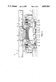
- FIG. 2 is a vertical cross-sectional view, on a larger scale, of a first embodiment of the conveying installation according to the present invention shown in FIG. 1 taken along sectional line II--II;
- FIG. 3 is a vertical cross-sectional view, on a larger scale, of a second embodiment of the conveying installation according to the present invention shown in FIG. 1 taken along sectional line II--II;
- FIG. 4 is a vertical cross-sectional view, on a larger scale, of a third embodiment of the conveying installation according to the present invention shown in FIG. 1 taken along sectional line II--II.
- the conveying installations in accordance with the present invention illustrated in FIGS. 1-4 are denoted by reference numeral 1.
- the conveying installations 1 may be used, for example, in an automobile factory.
- the conveying installations 1 include a stator 2 supplied by electric current.
- the stator 2 is placed along a travel path 3 for conveyor units 5, 5a.
- travel path 3 is formed by a concrete path. It is also conceivable that the conveyor units are guided on rails.
- Stator 2 is directed into several stator portions 4.
- the stator portions 4 are mutually electrically monitored in the conventional manner.
- the lengths L of each stator portion 4 is smaller than the minimum spacing between conveyor units 5, 5a which is determined by local conditions.
- Each stator portion 4 includes at least one braking device 6, 6a, 6b.
- the conveyor units 5, 5a include conveyor platforms 7.
- the conveyor units 5, 5a further include undercarriages 8 which roll on travel path 3 and are rotatably arranged relative to conveyor platform 7.
- undercarriages 8 may be provided for each conveyor unit 5, 5a.
- Each conveyor unit 5, 5a includes at least one permanent magnet 9 which is located a small distance above stator 2. Permanent magnet 9 may be mounted in conveyor unit 5, 5a in such a way that it can adapt in an optimum manner to the stator even in tight curves.
- the permanent magnet 9 can be mounted in such a way that it is rotatable in an end portion about the swivel axis of the undercarriage 8 and is transversely movable i the conveyor platform 7 with the other end portion.
- the supports necessary for this purpose are denoted with reference numeral 13 and the necessary rollers are denoted with reference numeral 14.
- Stator 2 is mounted on a stator support 10 which also serves as the guidance means for the conveyor units 5, 5a.
- the conveyor units 5, 5a have guide rollers 11 which are rotatable about vertical axes of and rest laterally against the stator support 10.
- the braking devices 6 illustrated in FIGS. 1 and 2 assigned to the stator portions 4 each include two electrically operated brake cylinders 15 which are biased by an elastic restoring force, not shown.
- Brake cylinders 15 including cylinder housing 16 are mounted so as to be pivotable about horizontal axis 17.
- the brake cylinders 15 extend underneath travel path 3 in recesses 18.
- the brake cylinders 15 include piston rods 19 which are hinged to the lower ends 20 of two-arm brake levers 21.
- the brake levers 21 are mounted so as to be pivotable about their middle points.
- Support brackets 22 for the brake levers 21 are mounted on the travel path 3.
- the connection 29 between piston rods 19 and brake levers 21 may be a resiliently yielding connection.
- Brake shoes with brake lining 25 are hinged to the upper ends 23 of brake levers 21.
- the brake shoes 24 are supported through spring 26.
- the conveyor units 5 have on their sides brake surfaces 27 on the same vertical level as the brake linings 25.
- the current supply to stator 2 is coupled to the current supply to brake cylinder 15.
- current is also supplied to brake cylinders 15, so that the brake shoes 24 are located at a distance from brake surfaces 27.
- the brake cylinders 15 are subjected to the elastic restoring force which brings the brake shoes 24 into contact with the brake surfaces 27 and stop the movement of the conveyor unit 5.
- FIG. 2 further shows in dash-dotted lines that it is also possible to use magnets 28 instead of the electrically actuated brake cylinders 15.
- FIG. 3 differs from that shown in FIG. 2 with respect to the braking device used. While the embodiment of FIG. 2 uses a braking device 6 with two brake cylinders 15 or two magnets 28, in the embodiment of FIG. 3 the brake levers 21 are actuated by a common brake cylinder 15a of a braking device 6a.
- Brake cylinder 15a is also accommodated in a recess 18 in travel path 3. Brake cylinder 15a is mounted in a floating manner with the cylinder housing 16a being hinged to the lower end 20 of the brake lever 21 on one side of stator 2 and the piston rod 19a being hinged to the lower end 20 of the brake lever 21 provided on the other side of the stator 2.
- brake lever 21 The pivoting movement of brake lever 21 is limited by stops 30.
- the braking devices 6b are arranged on the sides of stator 2. Each braking device 6b includes a brake cylinder 15b which extends essentially horizontally. Cylinder housing 16b is hinged to a counterbrake lever 21a which is pivotally mounted about a horizontal axis 31 on an abutment housing 32 fastened on the travel path 3. The pivoting movements of the counterbrake lever 21a are limited by stops 33.
- Brake shoes 24a are fastened to the other end of counterbrake lever 21a. Brake shoes 24a are provided with brake linings 25a which can come into contact with the underside of brake surfaces 27a. Brake surfaces 27a project horizontally from the conveyor unit 5a.
- the piston rods 19b of the brake cylinder 15b are hinged to the lower ends 20 of brake levers 21b.
- the upper ends are provided with brake shoes 24b which can come into contact with the brake linings 25a at the upper sides of the brake surfaces 27a.
- the pivoting movements of the brake lever 21b are limited by stops 34.
Landscapes
- Engineering & Computer Science (AREA)
- Mechanical Engineering (AREA)
- Chemical & Material Sciences (AREA)
- Combustion & Propulsion (AREA)
- Physics & Mathematics (AREA)
- Electromagnetism (AREA)
- Power Engineering (AREA)
- Transportation (AREA)
- Control Of Vehicles With Linear Motors And Vehicles That Are Magnetically Levitated (AREA)
- Braking Arrangements (AREA)
- Non-Mechanical Conveyors (AREA)
Applications Claiming Priority (2)
| Application Number | Priority Date | Filing Date | Title |
|---|---|---|---|
| DE19863641326 DE3641326A1 (de) | 1986-12-03 | 1986-12-03 | Foerderanlage |
| DE3641326 | 1986-12-03 |
Publications (1)
| Publication Number | Publication Date |
|---|---|
| US4819564A true US4819564A (en) | 1989-04-11 |
Family
ID=6315385
Family Applications (1)
| Application Number | Title | Priority Date | Filing Date |
|---|---|---|---|
| US07/127,510 Expired - Fee Related US4819564A (en) | 1986-12-03 | 1987-12-01 | Linear motor driven conveying installation and braking device therefor |
Country Status (5)
| Country | Link |
|---|---|
| US (1) | US4819564A (enExample) |
| DE (1) | DE3641326A1 (enExample) |
| FR (1) | FR2607767B1 (enExample) |
| GB (1) | GB2199294B (enExample) |
| IT (1) | IT1211883B (enExample) |
Cited By (17)
| Publication number | Priority date | Publication date | Assignee | Title |
|---|---|---|---|---|
| WO1992000862A1 (en) * | 1990-07-05 | 1992-01-23 | Utdc Inc. | Linear motor in-track transit system |
| US5116002A (en) * | 1990-07-05 | 1992-05-26 | Utdc, Inc. | Stopping zones in a linear motor in-track transit system |
| US5118055A (en) * | 1990-07-05 | 1992-06-02 | Utdc, Inc. | Reduced voltage braking system in a linear motor in-track transit system |
| US5127599A (en) * | 1990-07-05 | 1992-07-07 | Utdc, Inc. | Deceleration zone in a linear motor in-track transit system |
| US5158021A (en) * | 1990-12-28 | 1992-10-27 | Kajima Corporation | Ski lift with variable speed linear motor drive and emergency stop apparatus responsive to power loss to the drive |
| US5575218A (en) * | 1996-04-10 | 1996-11-19 | Newera Capital Corp. | Track brake apparatus with sliding shoes and wear plates for preventing excessive movement of the shoes in the direction of vehicle movement |
| US5626082A (en) * | 1993-07-30 | 1997-05-06 | Shinko Electric Co., Ltd. | Emergency braking device for linear motor driven transport system |
| US5778796A (en) * | 1994-06-21 | 1998-07-14 | Kim; In Ki | Switch system for personal rapid transit |
| US5992575A (en) * | 1996-03-23 | 1999-11-30 | Kim; In Ki | Personal rapid transit braking systems |
| US6029104A (en) * | 1995-11-08 | 2000-02-22 | Kim; In Ki | Position recognition apparatus for a personal rapid transit control system |
| EP1113568A3 (de) * | 1999-12-30 | 2002-03-20 | Bison stematec, Maschinenbau- und Hubarbeitsbühnen Produktionsgesellschaft mbH | Verriegelungselement für elektomagnetische lineare Antriebsvorrichtungen |
| CN1107606C (zh) * | 2000-06-16 | 2003-05-07 | 李岭群 | 磁浮动力舱 |
| EP1252051A4 (en) * | 2000-02-03 | 2003-05-21 | Skycar Co Ltd | QUICK PERSONAL TRANSPORT SYSTEM WITH LINEAR INDUCTION MOTOR ON THE BOTTOM OF THE VEHICLE |
| US6591757B1 (en) * | 2001-12-26 | 2003-07-15 | Anorad Corporation | Motor driven high stability brake for linear motion systems |
| US20110259236A1 (en) * | 2008-12-31 | 2011-10-27 | Sam-Young Kwon | Wheel-type ultra high speed railway system |
| US10848047B2 (en) * | 2018-06-05 | 2020-11-24 | B&R Industrial Automation GmbH | Method and long-stator linear motor for transferring a transport unit at a transfer position |
| US20230079695A1 (en) * | 2021-09-16 | 2023-03-16 | Rockwell Automation Technologies, Inc. | Brake system for track and mover system |
Citations (8)
| Publication number | Priority date | Publication date | Assignee | Title |
|---|---|---|---|---|
| US573823A (en) * | 1896-12-22 | lefpler | ||
| DE918167C (de) * | 1952-05-01 | 1954-09-20 | Froelich & Kluepfel | Beschickungsanlage fuer Foerderkoerbe |
| US3503471A (en) * | 1968-04-03 | 1970-03-31 | Eaton Yale & Towne | Monorail brake system |
| US3610372A (en) * | 1968-11-12 | 1971-10-05 | Koch Sons George | Pallet braking mechanism |
| US3616762A (en) * | 1968-09-25 | 1971-11-02 | Linerail Manutention Par Moteu | Overhead conveyor system |
| US3631809A (en) * | 1968-06-26 | 1972-01-04 | Tracked Hovercraft Ltd | Linear induction motor bail |
| US4348961A (en) * | 1980-07-07 | 1982-09-14 | Si Handling Systems, Inc. | Fail-safe control device for driverless vehicles |
| US4709639A (en) * | 1984-11-05 | 1987-12-01 | Robert Geais | Railway system utilizing a linear motor for propulsion of trains |
Family Cites Families (10)
| Publication number | Priority date | Publication date | Assignee | Title |
|---|---|---|---|---|
| GB725467A (en) * | 1953-04-21 | 1955-03-02 | Northrop Aircraft Inc | Improvements in or relating to controlled deceleration device |
| DE938071C (de) * | 1954-11-21 | 1956-01-19 | Demag Ag | Foerderwagen-Haltebremse, insbesondere vor den Aufschiebevorrichtungen an Haengebank und Fuellort |
| DE1080138B (de) * | 1957-12-05 | 1960-04-21 | Demag Ag | Foerderwagenbremse |
| DE2165342A1 (de) * | 1971-12-29 | 1973-07-12 | Siemens Ag | Trassengebundene fahrzeug-transporteinrichtung mit elektrischem antrieb und elektromagnetischer schwebefuehrung |
| DE2541599A1 (de) * | 1975-09-18 | 1977-03-24 | Weh Herbert | Integrierte magnetfahrtechnik fuer den nahverkehr |
| CH634514A5 (de) * | 1978-11-16 | 1983-02-15 | Schweizerische Bundesbahnen | Balkengleisbremse. |
| US4393960A (en) * | 1981-01-21 | 1983-07-19 | Aaa Sales & Engineering, Inc. | Low noise railroad retarder brake shoe structure |
| SE425647B (sv) * | 1981-03-24 | 1982-10-25 | Hegglund & Soner Ab | Vagnbroms for rangerendamal |
| JPS60229603A (ja) * | 1984-04-26 | 1985-11-15 | Toshiba Corp | 搬送装置 |
| JPS61142201A (ja) * | 1984-12-13 | 1986-06-30 | 株式会社東芝 | 搬送装置 |
-
1986
- 1986-12-03 DE DE19863641326 patent/DE3641326A1/de active Granted
-
1987
- 1987-10-27 IT IT8748542A patent/IT1211883B/it active
- 1987-11-27 GB GB8727859A patent/GB2199294B/en not_active Expired - Fee Related
- 1987-12-01 US US07/127,510 patent/US4819564A/en not_active Expired - Fee Related
- 1987-12-03 FR FR8716805A patent/FR2607767B1/fr not_active Expired - Fee Related
Patent Citations (8)
| Publication number | Priority date | Publication date | Assignee | Title |
|---|---|---|---|---|
| US573823A (en) * | 1896-12-22 | lefpler | ||
| DE918167C (de) * | 1952-05-01 | 1954-09-20 | Froelich & Kluepfel | Beschickungsanlage fuer Foerderkoerbe |
| US3503471A (en) * | 1968-04-03 | 1970-03-31 | Eaton Yale & Towne | Monorail brake system |
| US3631809A (en) * | 1968-06-26 | 1972-01-04 | Tracked Hovercraft Ltd | Linear induction motor bail |
| US3616762A (en) * | 1968-09-25 | 1971-11-02 | Linerail Manutention Par Moteu | Overhead conveyor system |
| US3610372A (en) * | 1968-11-12 | 1971-10-05 | Koch Sons George | Pallet braking mechanism |
| US4348961A (en) * | 1980-07-07 | 1982-09-14 | Si Handling Systems, Inc. | Fail-safe control device for driverless vehicles |
| US4709639A (en) * | 1984-11-05 | 1987-12-01 | Robert Geais | Railway system utilizing a linear motor for propulsion of trains |
Cited By (23)
| Publication number | Priority date | Publication date | Assignee | Title |
|---|---|---|---|---|
| US5116002A (en) * | 1990-07-05 | 1992-05-26 | Utdc, Inc. | Stopping zones in a linear motor in-track transit system |
| US5118055A (en) * | 1990-07-05 | 1992-06-02 | Utdc, Inc. | Reduced voltage braking system in a linear motor in-track transit system |
| US5127599A (en) * | 1990-07-05 | 1992-07-07 | Utdc, Inc. | Deceleration zone in a linear motor in-track transit system |
| WO1992000862A1 (en) * | 1990-07-05 | 1992-01-23 | Utdc Inc. | Linear motor in-track transit system |
| US5158021A (en) * | 1990-12-28 | 1992-10-27 | Kajima Corporation | Ski lift with variable speed linear motor drive and emergency stop apparatus responsive to power loss to the drive |
| US5626082A (en) * | 1993-07-30 | 1997-05-06 | Shinko Electric Co., Ltd. | Emergency braking device for linear motor driven transport system |
| US5778796A (en) * | 1994-06-21 | 1998-07-14 | Kim; In Ki | Switch system for personal rapid transit |
| US6029104A (en) * | 1995-11-08 | 2000-02-22 | Kim; In Ki | Position recognition apparatus for a personal rapid transit control system |
| US5992575A (en) * | 1996-03-23 | 1999-11-30 | Kim; In Ki | Personal rapid transit braking systems |
| US5575218A (en) * | 1996-04-10 | 1996-11-19 | Newera Capital Corp. | Track brake apparatus with sliding shoes and wear plates for preventing excessive movement of the shoes in the direction of vehicle movement |
| USRE36084E (en) * | 1996-04-10 | 1999-02-09 | Thrilltime Entertainment International, Inc. | Track brake apparatus with sliding shoes and wear plates for preventing excessive movement of the shoes in the direction of vehicle movement |
| EP1113568A3 (de) * | 1999-12-30 | 2002-03-20 | Bison stematec, Maschinenbau- und Hubarbeitsbühnen Produktionsgesellschaft mbH | Verriegelungselement für elektomagnetische lineare Antriebsvorrichtungen |
| EP1252051A4 (en) * | 2000-02-03 | 2003-05-21 | Skycar Co Ltd | QUICK PERSONAL TRANSPORT SYSTEM WITH LINEAR INDUCTION MOTOR ON THE BOTTOM OF THE VEHICLE |
| CN1107606C (zh) * | 2000-06-16 | 2003-05-07 | 李岭群 | 磁浮动力舱 |
| US6591757B1 (en) * | 2001-12-26 | 2003-07-15 | Anorad Corporation | Motor driven high stability brake for linear motion systems |
| US6715426B1 (en) * | 2001-12-26 | 2004-04-06 | Anorad Corporation | Motor driven high stability brake linear motion systems |
| US20110259236A1 (en) * | 2008-12-31 | 2011-10-27 | Sam-Young Kwon | Wheel-type ultra high speed railway system |
| US8505463B2 (en) * | 2008-12-31 | 2013-08-13 | Korea Railroad Research Institute | Wheel-type ultra high speed railway system |
| US10848047B2 (en) * | 2018-06-05 | 2020-11-24 | B&R Industrial Automation GmbH | Method and long-stator linear motor for transferring a transport unit at a transfer position |
| US20230079695A1 (en) * | 2021-09-16 | 2023-03-16 | Rockwell Automation Technologies, Inc. | Brake system for track and mover system |
| CN115818261A (zh) * | 2021-09-16 | 2023-03-21 | 罗克韦尔自动化技术公司 | 用于轨道和动子系统的制动系统 |
| EP4152580A1 (en) * | 2021-09-16 | 2023-03-22 | Rockwell Automation Technologies, Inc. | Brake system for track and mover system |
| US12005939B2 (en) * | 2021-09-16 | 2024-06-11 | Rockwell Automation Technologies, Inc. | Brake system for track and mover system |
Also Published As
| Publication number | Publication date |
|---|---|
| DE3641326A1 (de) | 1988-06-16 |
| DE3641326C2 (enExample) | 1989-09-07 |
| GB2199294A (en) | 1988-07-06 |
| GB8727859D0 (en) | 1987-12-31 |
| FR2607767A1 (fr) | 1988-06-10 |
| IT1211883B (it) | 1989-11-08 |
| GB2199294B (en) | 1991-01-02 |
| FR2607767B1 (fr) | 1995-09-08 |
| IT8748542A0 (it) | 1987-10-27 |
Similar Documents
| Publication | Publication Date | Title |
|---|---|---|
| US4819564A (en) | Linear motor driven conveying installation and braking device therefor | |
| US4660465A (en) | System for exhausting and collecting gases, in particular motor vehicle exhaust gases in assembly or factory halls | |
| US5199674A (en) | Multi-articulation switch | |
| EP3380385B1 (en) | Monorail switch using a gravity-assisted actuating mechanism | |
| US8302739B2 (en) | Brake device for a lift car | |
| CN110831881B (zh) | 用于电梯系统中旋转平台的支撑装置 | |
| GB2283001A (en) | Conveyor system having electrically propelled railcars. | |
| KR20120043184A (ko) | 시저스 타입 궤도 분기기의 회전거더 구동장치 | |
| KR101757783B1 (ko) | 오버헤드 컨베이어 | |
| KR102000701B1 (ko) | 제3궤조용 집전장치의 래치 장치 | |
| US4643100A (en) | Railway train set for the renewal of railway tracks, with support and advancement guide means | |
| US3783978A (en) | Stop control for elevators | |
| US5161758A (en) | Connecting system for trolley rails for transport vehicle | |
| US12077415B2 (en) | Apparatus for guiding and braking a travelling body of an elevator system, which body is to be moved along a guide track | |
| US3340822A (en) | Track switching device for air cushion vehicles | |
| EP0098738A2 (en) | Improvements in or relating to transporting systems for robots | |
| US4646646A (en) | Overhead trolley track switch | |
| JP2547476B2 (ja) | 鉄道の分岐装置 | |
| KR100307501B1 (ko) | 경량전철 제3궤조 집전장치 | |
| CA2267428A1 (en) | Operating system for lift doors | |
| JP7705864B2 (ja) | 軌道車両用の分岐装置 | |
| IT1249598B (it) | Impianto di sollevamento ausiliare di strada ferrata | |
| JP2016101823A (ja) | 搬送システム | |
| CN113272239A (zh) | 电梯系统 | |
| JP2606755B2 (ja) | 経路切換装置 |
Legal Events
| Date | Code | Title | Description |
|---|---|---|---|
| AS | Assignment |
Owner name: MASCHINENFABRIK SCHARF GMBH, ERMELINGHOFSTR. 14-16 Free format text: ASSIGNMENT OF ASSIGNORS INTEREST.;ASSIGNORS:BRANDIS, CURT;SCHULZE-BUXLOH, HEINRICH;PIRAGS, SIEGFRIED;REEL/FRAME:004798/0032 Effective date: 19871117 Owner name: MASCHINENFABRIK SCHARF GMBH, ERMELINGHOFSTR. 14-16 Free format text: ASSIGNMENT OF ASSIGNORS INTEREST;ASSIGNORS:BRANDIS, CURT;SCHULZE-BUXLOH, HEINRICH;PIRAGS, SIEGFRIED;REEL/FRAME:004798/0032 Effective date: 19871117 |
|
| REMI | Maintenance fee reminder mailed | ||
| FEPP | Fee payment procedure |
Free format text: PAYOR NUMBER ASSIGNED (ORIGINAL EVENT CODE: ASPN); ENTITY STATUS OF PATENT OWNER: LARGE ENTITY |
|
| FPAY | Fee payment |
Year of fee payment: 4 |
|
| SULP | Surcharge for late payment | ||
| REMI | Maintenance fee reminder mailed | ||
| LAPS | Lapse for failure to pay maintenance fees | ||
| FP | Lapsed due to failure to pay maintenance fee |
Effective date: 19970416 |
|
| STCH | Information on status: patent discontinuation |
Free format text: PATENT EXPIRED DUE TO NONPAYMENT OF MAINTENANCE FEES UNDER 37 CFR 1.362 |