US4772772A - Process for the supervision of the machining process using a high-power energy source, in particular a laser, and machining optical system for carrying out the same - Google Patents
Process for the supervision of the machining process using a high-power energy source, in particular a laser, and machining optical system for carrying out the same Download PDFInfo
- Publication number
- US4772772A US4772772A US07/068,302 US6830287A US4772772A US 4772772 A US4772772 A US 4772772A US 6830287 A US6830287 A US 6830287A US 4772772 A US4772772 A US 4772772A
- Authority
- US
- United States
- Prior art keywords
- mirror
- machining
- optical system
- laser
- machining optical
- Prior art date
- Legal status (The legal status is an assumption and is not a legal conclusion. Google has not performed a legal analysis and makes no representation as to the accuracy of the status listed.)
- Expired - Fee Related
Links
Images


Classifications
-
- B—PERFORMING OPERATIONS; TRANSPORTING
- B23—MACHINE TOOLS; METAL-WORKING NOT OTHERWISE PROVIDED FOR
- B23K—SOLDERING OR UNSOLDERING; WELDING; CLADDING OR PLATING BY SOLDERING OR WELDING; CUTTING BY APPLYING HEAT LOCALLY, e.g. FLAME CUTTING; WORKING BY LASER BEAM
- B23K26/00—Working by laser beam, e.g. welding, cutting or boring
- B23K26/02—Positioning or observing the workpiece, e.g. with respect to the point of impact; Aligning, aiming or focusing the laser beam
- B23K26/06—Shaping the laser beam, e.g. by masks or multi-focusing
- B23K26/064—Shaping the laser beam, e.g. by masks or multi-focusing by means of optical elements, e.g. lenses, mirrors or prisms
- B23K26/0643—Shaping the laser beam, e.g. by masks or multi-focusing by means of optical elements, e.g. lenses, mirrors or prisms comprising mirrors
-
- B—PERFORMING OPERATIONS; TRANSPORTING
- B23—MACHINE TOOLS; METAL-WORKING NOT OTHERWISE PROVIDED FOR
- B23K—SOLDERING OR UNSOLDERING; WELDING; CLADDING OR PLATING BY SOLDERING OR WELDING; CUTTING BY APPLYING HEAT LOCALLY, e.g. FLAME CUTTING; WORKING BY LASER BEAM
- B23K26/00—Working by laser beam, e.g. welding, cutting or boring
- B23K26/02—Positioning or observing the workpiece, e.g. with respect to the point of impact; Aligning, aiming or focusing the laser beam
- B23K26/03—Observing, e.g. monitoring, the workpiece
- B23K26/034—Observing the temperature of the workpiece
-
- B—PERFORMING OPERATIONS; TRANSPORTING
- B23—MACHINE TOOLS; METAL-WORKING NOT OTHERWISE PROVIDED FOR
- B23K—SOLDERING OR UNSOLDERING; WELDING; CLADDING OR PLATING BY SOLDERING OR WELDING; CUTTING BY APPLYING HEAT LOCALLY, e.g. FLAME CUTTING; WORKING BY LASER BEAM
- B23K26/00—Working by laser beam, e.g. welding, cutting or boring
- B23K26/02—Positioning or observing the workpiece, e.g. with respect to the point of impact; Aligning, aiming or focusing the laser beam
- B23K26/04—Automatically aligning, aiming or focusing the laser beam, e.g. using the back-scattered light
-
- B—PERFORMING OPERATIONS; TRANSPORTING
- B23—MACHINE TOOLS; METAL-WORKING NOT OTHERWISE PROVIDED FOR
- B23K—SOLDERING OR UNSOLDERING; WELDING; CLADDING OR PLATING BY SOLDERING OR WELDING; CUTTING BY APPLYING HEAT LOCALLY, e.g. FLAME CUTTING; WORKING BY LASER BEAM
- B23K26/00—Working by laser beam, e.g. welding, cutting or boring
- B23K26/70—Auxiliary operations or equipment
- B23K26/702—Auxiliary equipment
- B23K26/703—Cooling arrangements
-
- B—PERFORMING OPERATIONS; TRANSPORTING
- B23—MACHINE TOOLS; METAL-WORKING NOT OTHERWISE PROVIDED FOR
- B23K—SOLDERING OR UNSOLDERING; WELDING; CLADDING OR PLATING BY SOLDERING OR WELDING; CUTTING BY APPLYING HEAT LOCALLY, e.g. FLAME CUTTING; WORKING BY LASER BEAM
- B23K26/00—Working by laser beam, e.g. welding, cutting or boring
- B23K26/70—Auxiliary operations or equipment
- B23K26/702—Auxiliary equipment
- B23K26/705—Beam measuring device
-
- B—PERFORMING OPERATIONS; TRANSPORTING
- B23—MACHINE TOOLS; METAL-WORKING NOT OTHERWISE PROVIDED FOR
- B23K—SOLDERING OR UNSOLDERING; WELDING; CLADDING OR PLATING BY SOLDERING OR WELDING; CUTTING BY APPLYING HEAT LOCALLY, e.g. FLAME CUTTING; WORKING BY LASER BEAM
- B23K26/00—Working by laser beam, e.g. welding, cutting or boring
- B23K26/70—Auxiliary operations or equipment
- B23K26/702—Auxiliary equipment
- B23K26/707—Auxiliary equipment for monitoring laser beam transmission optics
Definitions
- the invention relates to a process for the supervision of a machining process using a high-power energy source, in particular a laser, and to a machining optical system for carrying out the process.
- High-power energy sources in particular electron beams or focused laser beams (CO 2 laser) which are employed for the machining of materials, namely cutting, welding and surface finishing, have appropriate beam-guiding optical systems which are adapted to the respective machining function.
- a matter of particular importance is the machining optical system of the laser, which optical system has a substantial influence on the quality of the machining operation to be carried out. In order to guarantee an optimal machining quality which is as uniform as possible during the entire machining operation, it is necessary to maintain the machining process at the workpiece constant.
- the decisive beam parameters are the beam power, the beam diameter, the position of the beam and the radiation reflected back, which can be subject to temporal fluctuations during the machining operation and must therefore be taken into consideration.
- the object of the invention is accordingly to provide a process and a machining optical system for the supervision of the machining process of a high-power laser (CO 2 laser), whereby the essential relevant parameters having an effect on the quality of the machining of the material may be determined.
- CO 2 laser high-power laser
- the relevant parameters of the laser beam are measured during the machining of the material, the possibility of comprehensive integrated process supervision is created, specifically where it is possible for the measurement to be carried out not only completely but also most simply and most reliably, namely at the machining optical system.
- This also has advantages if the laser is to be employed for other machining operations, which require no machining optical system or another machining optical system, because in those circumstances it is specifically the case that the sensitive measuring instruments which are no longer necessary in such cases no longer need to remain unused on the device.
- the measurement of the quantities required for the power of the laser beam, the position of the same in relation to the optical axis, the diameter of the laser beam, the degree of contamination of the mirrors (deflecting mirror, focusing mirror) and the laser radiation reflected back takes place at the machining optical system by means of appropriately designed measurement value receivers or transducers.
- the measurement of the relevant parameters mentioned above takes place cumulatively.
- FIG. 1 shows the schematic construction of a laser machining device in perspective representation
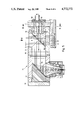
- FIG. 2 shows a vertical longitudinal section through a machining optical system according to a first exemplary embodiment
- FIG. 3 shows a side elevation of a surrounding mirror with a vertically cut housing cover and a thermal resistance disposed therebetween
- FIG. 4 shows a cross-section through the machining optical system according to FIG. 2 in the plane of three detectors associated with the deflecting mirror,
- FIG. 5 shows a vertical longitudinal section through a machining optical system of a second exemplary embodiment
- FIG. 6 shows a section VI--VI through the machining optical system according to FIG. 5,
- FIG. 7 shows an elevation in the direction of the arrow VII onto the mirror surface of the deflecting mirror
- FIG. 8 shows a deflecting mirror with sensors disposed on the mirror surface
- FIG. 9 shows a plan view onto the mirror surface of the deflecting mirror according to FIG. 8,
- FIG. 10 shows a detail X, represented oon an enlarged scale, of the deflecting mirror according to FIG. 8 cut in the region of a sensor, and
- FIG. 11 shows an alternative embodiment for the arrangement of the sensors on the mirror surface of the deflecting mirror in a representation according to FIG. 10.
- FIG. 1 shows, on an illustrative basis, the basic construction of a laser for carrying out the process according to the invention with the machining optical system according to the invention.
- the energy source which is employed in this case is a high-power laser, namely a CO 2 laser 20.
- a telescope 21 is situated at the beam output of the CO 2 laser 20.
- the telescope is connected to a beam-deflecting optical system 23 by means of a (horizontal) protecting tube 22.
- the laser beam coming through the protecting tube 22 is deflected out of the horizontal into a vertical beam direction.
- the laser beam From the beam-deflecting optical system 23, the laser beam finally passes through a further (vertical) protecting tube 24 to the machining optical system 25.
- the machining optical system 25 is constructed in such a manner that the laser beam is deflected in it twice, specifically by means of a deflecting mirror 26 from a vertical into a horizontal beam direction and from the latter again by means of a focusing mirror 27 into an exit direction - at right angles thereto -of the laser beam from the machining optical system.
- FIGS. 2 and 5 show furthermore that the laser beam leaves the machining optical system 25 in the form of a focused laser beam 28 in a vertical direction. Using a laser beam 28 focused in this manner, it is possible to carry out both cutting and welding machining operations and also surface finishing machining operations on a workpiece 29 (FIG. 1).
- FIGS. 2 and 5 also show the construction of the machining optical system 25.
- this optical system has an elongate, horizontally disposed housing 30 with a square cross-section.
- a longitudinally directed, circular throughbore 31 is disposed centrally in the housing 30.
- the mutually opposite end faces of the housing 30 are closed by respective covers 32 and 33 constructed in the manner of flanges.
- the housing 30 exhibits at least two openings in its walls, these being specifically an upper entrance opening 34 for the laser beam coming from the beam-deflecting optical system 23 and an exit opening 35 for the exit of the focused laser beam 28 from the machining optical system 25.
- the mirrors required for the deflection of the laser beam are also disposed in the housing 30 of the machining optical system 25.
- the cylindrically designed deflecting mirror 26 with a plane reflecting surface 36 inclined at 45° is associated with the entrance opening 34.
- the plane reflecting surface 36 deflects the laser beam entering vertically into the machining optical system 25 onto a laser beam continuing horizontally to the focusing mirror 27.
- the likewise cylindrical focusing mirror 27 is disposed at the side opposite the deflecting mirror 26 in the housing 30 and has a reflecting surface 37 which likewise extends at 45° but which is designed to be rotationally symmetrically concave.
- the mirrors (deflecting mirror 26; focusing mirror 27) which are centrally guided in the housing 30 are secured by respective (centric) threaded screws 38 to the respectively associated covers 32 and 33.
- respective thermal resistances 39 and 40 are associated with each mirror (deflecting mirror 26; focusing mirror 27).
- the thermal resistance 40 is disposed between the deflecting mirror 26 and the cover 33 associated with the latter, specifically resting on the plane, upright rear surface 41 of the deflecting mirror 26 on the one hand and the inner end surface 42, directed towards the same, of the cover 33 on the other hand.
- the deflecting mirror 40 is constructed as a circular disc with parallel, upright contact surfaces 43.
- a narrow bore 46 which opens in the contact surface 43 of the same directed towards the deflecting mirror 26.
- a further obliquely directed bore 47 in the cover 33 opens in front of the (outer) contact surface 43, directed towards the same, of the thermal resistance 40.
- the ends of the bores 46 and 47 directed towards the outer surface of the cover 33 are provided with clearances 48.
- appropriate detectors (not shown in FIGS. 2 and 3) may be accommodated in the cover 33, specifically in such a manner that their sensor tips open out to abut against the rear surface 41 of the deflecting mirror 26 on the one hand and the (outer) contact surface 43 of the thermal resistance 40 on the other hand.
- the detectors or the sensor tips of the same are preferably constructed as thermoelectric elements known per se.
- the thermal resistance 39 is constructed in a similar manner and disposed behind the focusing mirror 27; in this connection, appropriate bores 46 and 47 are provided in this case also for the association of sensor tips of appropriate detectors with the rear surface 41 of the focusing mirror 27 and with the contact surface 43 of the thermal resistance 39.
- the thermal resistances 39 and 40 serve for the measurement of the beam power as well as of the degree of contamination of the focusing mirror 27. This proceeds from the finding that a significant contamination of the machining optical system 25 takes place only at the focusing mirror 27, namely on the mirror surface 37 of the same, because only the focusing mirror 27, which is situated above the workpiece 29, is exposed to negative influences in consequence of the machining of the workpiece. On the other hand, a contamination of the deflecting mirror 26, which is situated so as to be protected in the machining optical system 25, is not to be expected. Accordingly, the degree of contamination of the focusing mirror 27 is obtained from a difference measurement between the temperatures at the deflecting mirror 26 and at the focusing mirror 27. For this purpose, the two thermal resistances 39 and 40 exhibit the same cross-section, the same thickness and the same heat transit time.
- the beam power is measured at the deflecting mirror 26, specifically by determination of the temperature gradient between the contact surface 43, directed towards the rear surface 41 of the deflecting mirror 26, of the thermal resistance 40 on the one hand and the opposite contact surface 43, directed towards the inner end face 42 of the cover 33, of the thermal resistance 40 on the other hand.
- the temperature gradient gives a measurement value varying in proportion to the beam power, whereby, following multiplication by an appropriate transmission coefficient, the beam power impinging on the deflecting mirror 26 can be determined directly from the temperature gradient.
- radially directed slits 49 are disposed both in the deflecting mirror 26 and also in the focusing mirror 27. These interrupt the appropriate mirror surfaces 36 and 37 respectively as well as the cylindrical envelope surface of the mirrors (deflecting mirror 26; focusing mirror 27) in narrow, elongate regions.
- the slits 49 are symmetrically distributed in relation to mirror surfaces 36 and 37 of the mirrors (deflecting mirror 26; focusing mirror 27). In the present case, three slits 49 offset in relation to one another by 120° in each instance are provided (FIG. 4).
- the slits 49 proceeding from the envelope surface of the mirrors (deflecting mirror 26; focusing mirror 27) are all directed to the centre point 50 of the mirror surfaces 36 and 37 respectively, and end, without contacting one another, at a slight spacing from the same.
- the width of the slits 49 is selected in such a manner that this is greater than the wavelength of the laser, for example 0.4 mm.
- the slits 49 do not proceed as far as the rear surfaces 41 of the mirrors (deflecting mirror 26; focusing mirror 27).
- the slit floor 51 produced thereby is constructed in an arched configuration, specifically in such a manner that the regions - entering the slits 49 from the mirror surface 36 or 37 - of the laser beam directed in the longitudinal direction in relation to the axis of the mirrors (deflecting mirror 26; focusing mirror 27) are deflected radially outwards by approximately 90° at the slit floors 51 and focused.
- the focal points 52 are of the regions of the laser beam which enter the slits 49 and are deflected at the slit floors 51 are situated at a spacing from the envelope surface outside the mirrors (deflecting mirror 26, focusing mirror 27).
- the slits 49 it is achieved that only partial regions of the laser beams incident in the longitudinal direction of the mirrors (deflecting mirror 26, focusing mirror 27) fall on the slit floors 51, and thus that transversely directed laser beams do not affect the slits 49.
- slits 49 it is also possible for appropriate segments projects in relation to the mirror surfaces 36, 37 to be arranged to conduct the regions of the laser beam which are intended for the measurement at the mirrors (deflecting mirror 26; focusing mirror 27).
- each one of the focal points 52 there is associated a detector 53, which is mounted in the housing 30 of the machining optical system 25 at a radial spacing from the mirrors (deflecting mirror 26; focusing mirror 27).
- the detectors 53 are preferably constructed as thermopiles of commercially conventional construction, which permit an optimal conversion of the infrared signals incident on the slits 49.
- the beam diameter can be determined from this value, by taking into consideration the dimensions of the slits 49, the number thereof and the measurement results at the detectors 53, in the case of a circular laser beam.
- the slits 49 or detectors 53 associated with the focusing mirror 27 also serve for the second measurement task, namely the determination of the position of the laser beam relative to the optical axis 54.
- the evaluation does not take place by a summation of the measurement results at the individual detectors 53; instead of this, the relative position of the laser beam is determined by difference measurements of the power incident in the (infrared) detectors 53, in that the centre of the laser beam in relation to the optical axis 54 is determined.
- the centre of the laser beam is obtained by evaluation on the basis of a polar coordinate system.
- the evaluation can take place in a Cartesian coordinate system.
- the (detection) slits 49 it is also possible to determine the laser radiation reflected back from the workpiece 29.
- the slits 49 disposed in the deflecting mirror 26 and the detectors 53 associated with the same serve for this purpose.
- the measurement results obtained at the deflecting mirror 26 it is possible to draw conclusions concerning the coupling-in of the laser beam at the workpiece 29.
- a weld seam may be detected or monitored in this manner, in that setting drives are associated with the machining optical system 25, which setting drives move the machining optical system 25 relative to the workpiece 29 as a function of the measurement result at the deflecting mirror 26, until the laser beams reflected back have reached a minimum which is an indication that an optimum of the laser radiation is absorbed by the workpiece 29, i.e. the weld seam or the like has been detected.
- FIGS. 5 to 7 show an alternative embodiment of a machining optical system 25, in which, in order to measure the beam position, the beam diameter and the laser beams reflected back, a multiplicity of bores distributed in the manner of a raster on the mirror surfaces 36 and 37 respectively of the mirrors are provided in place of the slits 49 which are present in the exemplary embodiment described above.
- the bores are disposed exclusively in the deflecting mirror 26, specifically as throughbores 55 extending parallel to the longitudinal centre line of the same and throughbores 56 extending transversely thereto.
- the throughbores exhibit a very small diameter, namely approximately only 0.5 mm.
- the diameters of the throughbores 55 and 56 respectively increase towards the rear surface of the deflecting mirror 26 in steps.
- FIG. 7 indicates the raster according to which the throughbores 55 and 26 are distributed on the mirror surface 37 of the deflecting mirror 26. According to this, a total of 24 throughbores are provided in this instance, namely 12 (horizontal) throughbores 55 and likewise 12 (vertical) throughbores 56. These are distributed in four horizontal rows 57 and seven vertical rows 58; the rows 57 and 58 which are outermost in each instance have a number of throughbores 55 and 56 respectively which is reduced by two. In FIG. 7, it is indicated by partial blackening of the throughbores 55 and 56 respectively whether these are united to a vertical or horizontal range circuit.
- the unblackened throughbores 55 and 56 respectively form the horizontal range circuits, while the half-blackened throughbores 55 and 56 respectively form the vertical range circuits. It becomes evident from this that three vertical range circuits and four horizontal range circuits are provided in the present exemplary embodiment.
- FIG. 5 also shows the association of detectors 59 with the throughbores 55 and 56 respectively.
- the horizontal throughbores 55 are continued in regions in the cover 33, and are connected by a bore 60 directed transversely thereto.
- the latter serves to accommodate one or more appropriate detectors, for example resistance thermometers consisting of wire. These can extend continuously over the entire range circuit (row 58), but can alternatively also be centrally divided, so that two detectors 59 in the form of resistance thermometers are associated with each range circuit (row 58).
- the detectors 61 can be constructed in a similar manner, namely also as resistance thermometers, which are accommodated in bores 62, extending transversely to the vertical throughbores 56, in the housing 30 of the machining optical system 25.
- the measurement of the diameter and of the position of the incident laser beam at the deflecting mirror 26 takes place with the aid of the vertical throughbores 56, while the measurement of the position, of the power - and, where appropriate, of the diameter - of the laser light reflected back by the workpiece 29 takes place with the aid of the horizontal throughbores 55.
- the evaluation of the measurement results obtained at the detectors 59 and 61 respectively takes place in this instance in a similar manner to that applicable in the case of the above-described exemplary embodiment with (detection) slits 49 disposed in the mirrors (deflecting mirror 26; focusing mirror 27)
- the throughbores 55 and 56 can also be distributed on the deflecting mirror 26 and the focusing mirror 27 in the case of this embodiment of the machining optical system 55 according to the invention, so that each mirror would then only have either vertical or horizontal throughbores.
- FIGS. 8 to 11 show an exemplary embodiment of the machining optical system 25 according to the invention, in which absorbing sensors 63 are disposed directly on the mirror surface 37 of the deflecting mirror 26.
- the sensors 63 can be constructed as filamentary resistance thermometers.
- the course of the sensors 63 disposed on the mirror surface 37 of the deflecting mirror 26 in this instance can be seen from FIG. 9.
- four sensors 63 constructed from wire wound in a U-shape are disposed to extend radially, distributed uniformly on the mirror surface 37, without meeting at the centre point 50 of the mirror surface 37.
- FIG. 10 shows the fitting of the sensors 63 on the mirror surface 37 of the deflecting mirror 26.
- approximately semicircular recesses 64 for the sensors 63 are disposed on the mirror surface 37, which are for the greater part filled with an insulator 65, in that in each instance a wire for the sensor 63 is embedded in such a manner that the mirror surface 37 remains plane, in spite of the sensors 63 disposed thereon.
- the insulator 65 preferably consists of an adhesive for the permanent fixing of the wire for the sensors 63 in the recesses 64 of the deflecting mirror 26.
- FIG. 11 An alternative embodiment of the fitting of the sensors 63 on the mirror surface 37 of the deflecting mirror 26 is shown in FIG. 11.
- the sensors 63 - which may likewise have the progression shown in FIG. 9 - are disposed so as to be elevated on the mirror surface 37.
- the sensors 63 are formed from a thin, laminated conductor, which is connected to the mirror surface 37 by an insulating layer 66.
- Such sensors 63 can be produced, for example, by vapour deposition on the mirror surface 37 of the deflecting mirror 26.
Landscapes
- Physics & Mathematics (AREA)
- Optics & Photonics (AREA)
- Engineering & Computer Science (AREA)
- Plasma & Fusion (AREA)
- Mechanical Engineering (AREA)
- Laser Beam Processing (AREA)
- Photometry And Measurement Of Optical Pulse Characteristics (AREA)
Applications Claiming Priority (2)
| Application Number | Priority Date | Filing Date | Title |
|---|---|---|---|
| DE19863623409 DE3623409A1 (de) | 1986-07-11 | 1986-07-11 | Verfahren zur ueberwachung des bearbeitungsprozesses mit einer hochleistungsenergiequelle, insbesondere einem laser, und bearbeitungsoptik zur durchfuehrung desselben |
| DE3623409 | 1986-07-11 |
Publications (1)
| Publication Number | Publication Date |
|---|---|
| US4772772A true US4772772A (en) | 1988-09-20 |
Family
ID=6304957
Family Applications (1)
| Application Number | Title | Priority Date | Filing Date |
|---|---|---|---|
| US07/068,302 Expired - Fee Related US4772772A (en) | 1986-07-11 | 1987-07-01 | Process for the supervision of the machining process using a high-power energy source, in particular a laser, and machining optical system for carrying out the same |
Country Status (4)
| Country | Link |
|---|---|
| US (1) | US4772772A (de) |
| EP (1) | EP0252268B1 (de) |
| JP (1) | JPS6330191A (de) |
| DE (2) | DE3623409A1 (de) |
Cited By (15)
| Publication number | Priority date | Publication date | Assignee | Title |
|---|---|---|---|---|
| US5004338A (en) * | 1989-03-01 | 1991-04-02 | Morrow Clifford E | Method and apparatus for attenuation and measurement of laser power at the end of a laser guide |
| US5026979A (en) * | 1990-03-05 | 1991-06-25 | General Electric Company | Method and apparatus for optically monitoring laser materials processing |
| US5045669A (en) * | 1990-03-02 | 1991-09-03 | General Electric Company | Method and apparatus for optically/acoustically monitoring laser materials processing |
| US5159402A (en) * | 1990-03-26 | 1992-10-27 | General Electric Company | Optical sensor safety system for monitoring laser crystals and optical components |
| DE4212652A1 (de) * | 1992-04-15 | 1993-10-28 | Weidmueller Interface | Laserbearbeitungskopf mit induktivem Abstandssensor |
| DE19630437A1 (de) * | 1996-07-27 | 1998-01-29 | Jurca Optoelektronik Gmbh | Vorrichtung zum Bearbeiten, beispielsweise Schweißen und Schneiden, eines Werkstückes mittels eines Bearbeitungslaserstrahles sowie Detektorvorrichtung zum Anbau an eine solche Vorrichtung |
| WO1998050196A1 (en) * | 1997-05-07 | 1998-11-12 | Institutet För Verkstadsteknisk Forskning | Device for detecting and calculating the focus point position, shape and power distribution of a laser beam |
| EP0917924A3 (de) * | 1997-11-21 | 2004-09-29 | Northrop Grumman Corporation | Spiegelbruchdetektor für Hochleistungslaser |
| US20050237019A1 (en) * | 2001-06-01 | 2005-10-27 | Thyssen Laser-Technik Gmbh | Method and device for the robot-controlled cutting of workpieces to be assembled by means of laser radiation |
| EP1649967A1 (de) * | 2004-10-20 | 2006-04-26 | Trumpf Werkzeugmaschinen GmbH + Co. KG | Optisches Element eines Laserbearbeitungskopfs |
| US20070295702A1 (en) * | 2004-11-09 | 2007-12-27 | Commissariat A L'energie Atomique | System and Process for Production of Nanometric or Sub-Micrometric Powders in Continuous Flus Under the Action of a Pyrolysis Laser |
| US20090107963A1 (en) * | 2006-04-28 | 2009-04-30 | Trumpf Werkzeugmaschinen Gmbh + Co. Kg | Laser Processing Machine and Method |
| US20150053659A1 (en) * | 2002-04-18 | 2015-02-26 | Applied Materials, Inc. | Thermal processing by scanning a laser line beam |
| US9839975B2 (en) | 2013-12-12 | 2017-12-12 | Bystronic Laser Ag | Method for configuring a laser machining machine |
| US9937590B2 (en) | 2010-07-22 | 2018-04-10 | Bystronic Laser Ag | Laser processing machine |
Families Citing this family (7)
| Publication number | Priority date | Publication date | Assignee | Title |
|---|---|---|---|---|
| JPH03216287A (ja) * | 1990-01-19 | 1991-09-24 | Fanuc Ltd | レーザ切断加工方法 |
| DE4006622C2 (de) * | 1990-03-02 | 1993-10-14 | Fraunhofer Ges Forschung | Vorrichtung zum Überwachen von mit Laserstrahlung bearbeiteten Werkstücken |
| FR2682476B1 (fr) * | 1991-10-10 | 1995-03-31 | Cheval Freres Sa | Procede pour la detection et la mesure de l'energie emise par une source laser et dispositif pour sa mise en óoeuvre. |
| JPH09501104A (ja) * | 1993-05-19 | 1997-02-04 | フラウンホーファー−ゲゼルシャフト ツル フェルデルング デル アンゲヴァンテン フォルシュング エー ファウ | ダイオードビームを用いた材料加工方法 |
| DE19852302A1 (de) * | 1998-11-12 | 2000-05-25 | Fraunhofer Ges Forschung | Verfahren und Vorrichtung zum Bearbeiten von Werkstücken mit Hochenergiestrahlung |
| DE10310854B3 (de) * | 2003-03-11 | 2004-09-30 | Erlas Erlanger Lasertechnik Gmbh | Verfahren, Überwachungsvorrichtung und Laserbearbeitungsanlage mit Fehlstellenüberwachung einer optischen Komponente |
| DE102012100721B3 (de) * | 2012-01-30 | 2013-04-11 | Trumpf Werkzeugmaschinen Gmbh + Co. Kg | Verfahren zum Regeln eines Laserschneidprozesses und Laserschneidmaschine |
Citations (8)
| Publication number | Priority date | Publication date | Assignee | Title |
|---|---|---|---|---|
| DE140117C (de) * | ||||
| US3441973A (en) * | 1967-09-19 | 1969-05-06 | Albert Turk | Mop wringer with gear driven rolls |
| JPS586785A (ja) * | 1981-06-16 | 1983-01-14 | Toshiba Corp | レ−ザ加工装置 |
| JPS58205689A (ja) * | 1982-05-24 | 1983-11-30 | Hitachi Ltd | レ−ザビ−ムの反射光量検出方法 |
| JPS5927793A (ja) * | 1982-08-09 | 1984-02-14 | Toshiba Corp | レ−ザ光光路保護カバ− |
| JPS60102290A (ja) * | 1983-11-09 | 1985-06-06 | Hitachi Ltd | レ−ザ加工装置 |
| US4648400A (en) * | 1985-05-06 | 1987-03-10 | Rts Laboratories, Inc. | Ophthalmic surgery system |
| US4675501A (en) * | 1983-10-29 | 1987-06-23 | Trumpf Gmbh & Co. | Laser apparatus with novel beam aligning means and method of laser processing of workpieces using same |
Family Cites Families (12)
| Publication number | Priority date | Publication date | Assignee | Title |
|---|---|---|---|---|
| US4019381A (en) * | 1976-01-12 | 1977-04-26 | The United States Of America As Represented By The Secretary Of The Army | Transparent optical power meter |
| DD143383A3 (de) * | 1978-04-20 | 1980-08-20 | Manfred Poehler | Anordnung zur stabilisierung einer laserstrahlung |
| DD140117B1 (de) * | 1978-12-27 | 1981-07-29 | Manfred Poehler | Anordnung zur praezisionsmaterialbearbeitung mittels laserstrahlen |
| DE2949564C2 (de) * | 1979-12-10 | 1981-11-12 | Gerhard Dr. 8012 Ottobrunn Busse | Einrichtung zur Messung der Strahlungsleistung von leisuntgsmodulierten optischen Sendern, insbesondere von Lasern |
| US4262198A (en) * | 1979-07-30 | 1981-04-14 | California Institute Of Technology | Broadband optical radiation detector |
| DE3134555A1 (de) * | 1980-09-02 | 1982-07-08 | Amada Co. Ltd., Isehara, Kanagawa | "verfahren und einrichtung zur bestimmung der fokussierposition bei lasereinrichtungen, insbesondere laser-bearbeitungsmaschinen u.dgl." |
| JPS57134148A (en) * | 1981-02-16 | 1982-08-19 | Olympus Optical Co | Detector of leading end output of laser knife |
| DE8227494U1 (de) * | 1982-09-30 | 1983-02-17 | Arnold, Peter, Dr., 8000 München | Vorrichtung zur messung der intensitaet eines laserstrahls |
| JPS5964188A (ja) * | 1982-10-05 | 1984-04-12 | Asahi Optical Co Ltd | レ−ザ−光用ビ−ムベンダ−位置検出装置 |
| DE3411126A1 (de) * | 1984-03-26 | 1985-10-03 | BIAS Forschungs- und Entwicklungs-Labor für angewandte Strahltechnik GmbH, 2820 Bremen | Vorrichtung zur bearbeitung von werkstuecken durch einen energiestrahl hoher leistungsdichte, insbesondere einem laserstrahl eines co(pfeil abwaerts)2(pfeil abwaerts)-lasers |
| US4695698A (en) * | 1984-07-10 | 1987-09-22 | Larassay Holding Ag | Method of, and apparatus for, generating a predetermined pattern using laser radiation |
| DD227364A1 (de) * | 1984-10-22 | 1985-09-18 | Univ Schiller Jena | Anordnung zur steuerung von verfahrensparametern bei der werkstoffbearbeitung mittels laserstrahlen |
-
1986
- 1986-07-11 DE DE19863623409 patent/DE3623409A1/de not_active Withdrawn
-
1987
- 1987-05-27 DE DE8787107712T patent/DE3777702D1/de not_active Expired - Lifetime
- 1987-05-27 EP EP87107712A patent/EP0252268B1/de not_active Expired - Lifetime
- 1987-07-01 US US07/068,302 patent/US4772772A/en not_active Expired - Fee Related
- 1987-07-09 JP JP62169932A patent/JPS6330191A/ja active Pending
Patent Citations (8)
| Publication number | Priority date | Publication date | Assignee | Title |
|---|---|---|---|---|
| DE140117C (de) * | ||||
| US3441973A (en) * | 1967-09-19 | 1969-05-06 | Albert Turk | Mop wringer with gear driven rolls |
| JPS586785A (ja) * | 1981-06-16 | 1983-01-14 | Toshiba Corp | レ−ザ加工装置 |
| JPS58205689A (ja) * | 1982-05-24 | 1983-11-30 | Hitachi Ltd | レ−ザビ−ムの反射光量検出方法 |
| JPS5927793A (ja) * | 1982-08-09 | 1984-02-14 | Toshiba Corp | レ−ザ光光路保護カバ− |
| US4675501A (en) * | 1983-10-29 | 1987-06-23 | Trumpf Gmbh & Co. | Laser apparatus with novel beam aligning means and method of laser processing of workpieces using same |
| JPS60102290A (ja) * | 1983-11-09 | 1985-06-06 | Hitachi Ltd | レ−ザ加工装置 |
| US4648400A (en) * | 1985-05-06 | 1987-03-10 | Rts Laboratories, Inc. | Ophthalmic surgery system |
Cited By (24)
| Publication number | Priority date | Publication date | Assignee | Title |
|---|---|---|---|---|
| US5004338A (en) * | 1989-03-01 | 1991-04-02 | Morrow Clifford E | Method and apparatus for attenuation and measurement of laser power at the end of a laser guide |
| US5045669A (en) * | 1990-03-02 | 1991-09-03 | General Electric Company | Method and apparatus for optically/acoustically monitoring laser materials processing |
| US5026979A (en) * | 1990-03-05 | 1991-06-25 | General Electric Company | Method and apparatus for optically monitoring laser materials processing |
| US5159402A (en) * | 1990-03-26 | 1992-10-27 | General Electric Company | Optical sensor safety system for monitoring laser crystals and optical components |
| DE4212652A1 (de) * | 1992-04-15 | 1993-10-28 | Weidmueller Interface | Laserbearbeitungskopf mit induktivem Abstandssensor |
| DE19630437C2 (de) * | 1996-07-27 | 2003-04-03 | Jurca Optoelektronik Gmbh | Detektorvorrichtung |
| US5938953A (en) * | 1996-07-27 | 1999-08-17 | Jurca Optoelektronik Gmbh | Laser beam apparatus for machining a workpiece |
| DE19630437A1 (de) * | 1996-07-27 | 1998-01-29 | Jurca Optoelektronik Gmbh | Vorrichtung zum Bearbeiten, beispielsweise Schweißen und Schneiden, eines Werkstückes mittels eines Bearbeitungslaserstrahles sowie Detektorvorrichtung zum Anbau an eine solche Vorrichtung |
| WO1998050196A1 (en) * | 1997-05-07 | 1998-11-12 | Institutet För Verkstadsteknisk Forskning | Device for detecting and calculating the focus point position, shape and power distribution of a laser beam |
| US6151109A (en) * | 1997-05-07 | 2000-11-21 | Institutet For Verkstadsteknisk Forskning | Device for detecting and calculating the focus point position, shape and power distribution of a laser beam |
| EP0917924A3 (de) * | 1997-11-21 | 2004-09-29 | Northrop Grumman Corporation | Spiegelbruchdetektor für Hochleistungslaser |
| US7248940B2 (en) * | 2001-06-01 | 2007-07-24 | Thyssen Laser-Technik Gmbh | Method and device for the robot-controlled cutting of workpieces to be assembled by means of laser radiation |
| US20050237019A1 (en) * | 2001-06-01 | 2005-10-27 | Thyssen Laser-Technik Gmbh | Method and device for the robot-controlled cutting of workpieces to be assembled by means of laser radiation |
| US20150053659A1 (en) * | 2002-04-18 | 2015-02-26 | Applied Materials, Inc. | Thermal processing by scanning a laser line beam |
| US9737959B2 (en) * | 2002-04-18 | 2017-08-22 | Applied Materials, Inc. | Thermal processing by scanning a laser line beam |
| US7947923B2 (en) | 2004-10-20 | 2011-05-24 | Trumpf Werkzeugmaschinen Gmbh + Co. Kg | Encoded optical element of a laser processing head |
| EP1649967A1 (de) * | 2004-10-20 | 2006-04-26 | Trumpf Werkzeugmaschinen GmbH + Co. KG | Optisches Element eines Laserbearbeitungskopfs |
| US20070295702A1 (en) * | 2004-11-09 | 2007-12-27 | Commissariat A L'energie Atomique | System and Process for Production of Nanometric or Sub-Micrometric Powders in Continuous Flus Under the Action of a Pyrolysis Laser |
| US8822878B2 (en) * | 2004-11-09 | 2014-09-02 | Commissariat A L'energie Atomique | Production of nanometric or sub-micrometric powders in continuous flux |
| US20090107963A1 (en) * | 2006-04-28 | 2009-04-30 | Trumpf Werkzeugmaschinen Gmbh + Co. Kg | Laser Processing Machine and Method |
| US9937590B2 (en) | 2010-07-22 | 2018-04-10 | Bystronic Laser Ag | Laser processing machine |
| US20180161938A1 (en) * | 2010-07-22 | 2018-06-14 | Bystronic Laser Ag | Laser processing machine |
| US10086475B2 (en) * | 2010-07-22 | 2018-10-02 | Bystronic Laser Ag | Laser processing machine |
| US9839975B2 (en) | 2013-12-12 | 2017-12-12 | Bystronic Laser Ag | Method for configuring a laser machining machine |
Also Published As
| Publication number | Publication date |
|---|---|
| EP0252268A3 (en) | 1989-02-01 |
| DE3623409A1 (de) | 1988-01-21 |
| EP0252268B1 (de) | 1992-03-25 |
| DE3777702D1 (de) | 1992-04-30 |
| EP0252268A2 (de) | 1988-01-13 |
| JPS6330191A (ja) | 1988-02-08 |
Similar Documents
| Publication | Publication Date | Title |
|---|---|---|
| US4772772A (en) | Process for the supervision of the machining process using a high-power energy source, in particular a laser, and machining optical system for carrying out the same | |
| US4626649A (en) | Control device for the automatic alignment of a laser beam | |
| US11255723B2 (en) | Beam power measurement with widening | |
| JP5558629B2 (ja) | レーザ加工装置 | |
| EP1102970B1 (de) | Ein sensor zum messen einer substrattemperatur | |
| US4172383A (en) | Method and an apparatus for simultaneous measurement of both temperature and emissivity of a heated material | |
| EP0304664B1 (de) | Detektor zum Ausrichten von Hochleistungslasern | |
| KR100635956B1 (ko) | 다중 센서 요소를 구비한 방사 온도계 및 방사 센서와 그온도 결정 방법 | |
| US4556875A (en) | Irradiated power monitoring system for optical fiber | |
| JP7504743B2 (ja) | 材料加工用機械のレーザビームの伝播経路に沿って配置された光学素子の動作状態を検出する方法、当該方法を実行するためのシステム、及び当該システムを備えるレーザ加工機 | |
| EP2856092B1 (de) | Laserleistungssensor | |
| US4848902A (en) | Device for measuring the intensity profile of a laser beam | |
| JPS6239077B2 (de) | ||
| Hård et al. | Accurate laser light-scattering measurements of capillary waves | |
| EP0708318A1 (de) | Strahlunsmessung durch Richtungsfiltrieren zur bestimmung der Temperatur eines strahlenden Objektes | |
| Miller et al. | Interferometer for measuring fast changes of refractive index and temperature in transparent liquids | |
| US6025587A (en) | Device for the detection of optical parameters of a laser beam | |
| US6273603B1 (en) | Measuring head for use in radiant energy flash measuring of the thermal diffusivity of samples | |
| US4362388A (en) | Remote measurement of concentration of a gas specie by resonance absorption | |
| GB2151871A (en) | Laser weapon detector | |
| US20180087959A1 (en) | Laser power and energy sensor using anisotropic thermoelectric material | |
| Kraus | Optical spectral radiometric/laser reflectance method for noninvasive measurement of weld pool surface temperatures | |
| US4073590A (en) | Laser total reflectometer | |
| US20250237546A1 (en) | Ion beam time of arrival (toa) gauge | |
| JPH0795612B2 (ja) | レ−ザ装置 |
Legal Events
| Date | Code | Title | Description |
|---|---|---|---|
| AS | Assignment |
Owner name: BIAS ROSCHUNGS UND ENTIWICK- LUNGSLABOR FUR ANGEWA Free format text: ASSIGNMENT OF ASSIGNORS INTEREST.;ASSIGNORS:JUPTNER, WERNER;ROTHE, RUDIGER;SEPOLD, GERD;REEL/FRAME:004912/0935 Effective date: 19870619 Owner name: BIAS ROSCHUNGS UND ENTIWICK- LUNGSLABOR FUR ANGEWA Free format text: ASSIGNMENT OF ASSIGNORS INTEREST;ASSIGNORS:JUPTNER, WERNER;ROTHE, RUDIGER;SEPOLD, GERD;REEL/FRAME:004912/0935 Effective date: 19870619 |
|
| FEPP | Fee payment procedure |
Free format text: PAYER NUMBER DE-ASSIGNED (ORIGINAL EVENT CODE: RMPN); ENTITY STATUS OF PATENT OWNER: SMALL ENTITY Free format text: PAYOR NUMBER ASSIGNED (ORIGINAL EVENT CODE: ASPN); ENTITY STATUS OF PATENT OWNER: SMALL ENTITY |
|
| FPAY | Fee payment |
Year of fee payment: 4 |
|
| REMI | Maintenance fee reminder mailed | ||
| LAPS | Lapse for failure to pay maintenance fees | ||
| FP | Lapsed due to failure to pay maintenance fee |
Effective date: 19960925 |
|
| STCH | Information on status: patent discontinuation |
Free format text: PATENT EXPIRED DUE TO NONPAYMENT OF MAINTENANCE FEES UNDER 37 CFR 1.362 |