US4740337A - Powder slush process for making plastic articles - Google Patents
Powder slush process for making plastic articles Download PDFInfo
- Publication number
- US4740337A US4740337A US06/866,948 US86694886A US4740337A US 4740337 A US4740337 A US 4740337A US 86694886 A US86694886 A US 86694886A US 4740337 A US4740337 A US 4740337A
- Authority
- US
- United States
- Prior art keywords
- mold
- cavity
- salt bath
- temperature
- salt
- Prior art date
- Legal status (The legal status is an assumption and is not a legal conclusion. Google has not performed a legal analysis and makes no representation as to the accuracy of the status listed.)
- Expired - Fee Related
Links
Images
Classifications
-
- B—PERFORMING OPERATIONS; TRANSPORTING
- B29—WORKING OF PLASTICS; WORKING OF SUBSTANCES IN A PLASTIC STATE IN GENERAL
- B29C—SHAPING OR JOINING OF PLASTICS; SHAPING OF MATERIAL IN A PLASTIC STATE, NOT OTHERWISE PROVIDED FOR; AFTER-TREATMENT OF THE SHAPED PRODUCTS, e.g. REPAIRING
- B29C33/00—Moulds or cores; Details thereof or accessories therefor
- B29C33/34—Moulds or cores; Details thereof or accessories therefor movable, e.g. to or from the moulding station
- B29C33/36—Moulds or cores; Details thereof or accessories therefor movable, e.g. to or from the moulding station continuously movable in one direction, e.g. in a closed circuit
-
- B—PERFORMING OPERATIONS; TRANSPORTING
- B29—WORKING OF PLASTICS; WORKING OF SUBSTANCES IN A PLASTIC STATE IN GENERAL
- B29C—SHAPING OR JOINING OF PLASTICS; SHAPING OF MATERIAL IN A PLASTIC STATE, NOT OTHERWISE PROVIDED FOR; AFTER-TREATMENT OF THE SHAPED PRODUCTS, e.g. REPAIRING
- B29C35/00—Heating, cooling or curing, e.g. crosslinking or vulcanising; Apparatus therefor
- B29C35/02—Heating or curing, e.g. crosslinking or vulcanizing during moulding, e.g. in a mould
- B29C35/04—Heating or curing, e.g. crosslinking or vulcanizing during moulding, e.g. in a mould using liquids, gas or steam
-
- B—PERFORMING OPERATIONS; TRANSPORTING
- B29—WORKING OF PLASTICS; WORKING OF SUBSTANCES IN A PLASTIC STATE IN GENERAL
- B29C—SHAPING OR JOINING OF PLASTICS; SHAPING OF MATERIAL IN A PLASTIC STATE, NOT OTHERWISE PROVIDED FOR; AFTER-TREATMENT OF THE SHAPED PRODUCTS, e.g. REPAIRING
- B29C41/00—Shaping by coating a mould, core or other substrate, i.e. by depositing material and stripping-off the shaped article; Apparatus therefor
- B29C41/02—Shaping by coating a mould, core or other substrate, i.e. by depositing material and stripping-off the shaped article; Apparatus therefor for making articles of definite length, i.e. discrete articles
- B29C41/18—Slush casting, i.e. pouring moulding material into a hollow mould with excess material being poured off
-
- B—PERFORMING OPERATIONS; TRANSPORTING
- B29—WORKING OF PLASTICS; WORKING OF SUBSTANCES IN A PLASTIC STATE IN GENERAL
- B29C—SHAPING OR JOINING OF PLASTICS; SHAPING OF MATERIAL IN A PLASTIC STATE, NOT OTHERWISE PROVIDED FOR; AFTER-TREATMENT OF THE SHAPED PRODUCTS, e.g. REPAIRING
- B29C41/00—Shaping by coating a mould, core or other substrate, i.e. by depositing material and stripping-off the shaped article; Apparatus therefor
- B29C41/34—Component parts, details or accessories; Auxiliary operations
- B29C41/46—Heating or cooling
-
- B—PERFORMING OPERATIONS; TRANSPORTING
- B29—WORKING OF PLASTICS; WORKING OF SUBSTANCES IN A PLASTIC STATE IN GENERAL
- B29C—SHAPING OR JOINING OF PLASTICS; SHAPING OF MATERIAL IN A PLASTIC STATE, NOT OTHERWISE PROVIDED FOR; AFTER-TREATMENT OF THE SHAPED PRODUCTS, e.g. REPAIRING
- B29C35/00—Heating, cooling or curing, e.g. crosslinking or vulcanising; Apparatus therefor
- B29C35/16—Cooling
-
- Y—GENERAL TAGGING OF NEW TECHNOLOGICAL DEVELOPMENTS; GENERAL TAGGING OF CROSS-SECTIONAL TECHNOLOGIES SPANNING OVER SEVERAL SECTIONS OF THE IPC; TECHNICAL SUBJECTS COVERED BY FORMER USPC CROSS-REFERENCE ART COLLECTIONS [XRACs] AND DIGESTS
- Y10—TECHNICAL SUBJECTS COVERED BY FORMER USPC
- Y10S—TECHNICAL SUBJECTS COVERED BY FORMER USPC CROSS-REFERENCE ART COLLECTIONS [XRACs] AND DIGESTS
- Y10S425/00—Plastic article or earthenware shaping or treating: apparatus
- Y10S425/039—Pre-heat
Definitions
- the present invention relates generally to plastic molding and more particularly to a process and apparatus for forming molded plastic articles, such as automotive parts, dashboards and the like.
- the desired mold temperature is determined by overheating the mold and then allowing the mold to cool for a predetermined time, selected based upon a previously measured or known time-temperature curve for the mold being used.
- achieving the correct mold temperature is a matter of controlling the time after the mold is removed from the heating oven until the plastic material is added.
- the accuracy of such a technique in achieving the correct mold temperature thus depends upon the accuracy of the time-temperature curves for the particular mold.
- different molds may have subtle or even substantial differences in time-temperature characteristics, so that the optimum mold temperature is at best an approximation. Deviations from the optimum mold temperature can result in lack of uniformity in the molded articles and high scrap rates or reject rates.
- the present invention overcomes the above deficiencies by providing a process and apparatus for forming molded plastic articles in which the mold is heated by contact with a heated salt bath.
- the mold temperature is monitored by a noncontact sensor while the mold is in the salt bath.
- the mold is removed from the salt bath and a plastic material is added as soon as the optimum mold temperture is reached.
- the invention thus places no critical reliance on time-temperature curves, which can vary from mold to mold.
- the salt bath is self-insulating; hence, very little waste heat is lost to the environment.
- a process for forming a molded plastic article comprises providing a mold having a cavity and an external surface, and also providing a salt bath at a first predeterminded temperature.
- the cavity is heated by contacting the external surface of the mold with the salt bath, the mold is then removed from the salt bath and a plastic material is placed in the heated cavity and is allowed to cure into the plastic article.
- the plastic article is then removed from the cavity.
- the invention also provides a method for forming a molded plastic article comprising providing a mold having a cavity and exposing the mold to a heat source. While the mold is exposed to the heat source, the mold temperature is sensed and the mold is removed from the heat source when a predetermined mold temperature is reached. A plastic material is then placed in the cavity and allowed to cure into the plastic article. The plastic article is then removed from the cavity.
- the invention is well adapted for automated assembly line applications.
- the invention also provides an apparatus for forming a molded plastic article comprising a salt bath heating station having a means associated with the heating station for sensing mold temperature.
- the apparatus provides at least one mold having an internal cavity and an external surface.
- a charging station is also provided, including a container for holding a supply of plastic material, the container having an opening therein through which a charge of plastic material may be introduced into the mold cavity.
- the invention further comprises a means for placing the external surface of the mold in contact with the salt bath, to thereby heat the internal cavity.
- a means for conveying the mold from the heating station to the charging station is also provided.
- the invention further comprises a means for placing the mold in registration with the container opening, with the cavity facing into the opening.
- the invention provides a means for simultaneously rotating the mold and the container about a common axis to thereby introduce a charge of plastic material into the cavity.
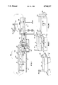
- FIG. 1 is an overall system view of the invention
- FIG. 2 is a diagrammatic perspective view illustrating the heating of the mold by contacting the external surface with a salt bath
- FIG. 3 is a diagrammatic perspective view depicting the position of the mold and slush box container prior to registration with one another;
- FIG. 4 is a diagrammatic perspective view illustrating the slush box and mold clamped together for mutual rotation.
- the invention may be viewed as comprising a number of stations at which given processes are performed upon a given mold and its contents.
- the presently preferred embodiment uses a power and free conveyor 10 to transport or convey one or more mold assemblies from station to station.
- six mold assemblies, each designated by reference numeral 12, are illustrated at selected stations.
- the first station is the preheating salt bath station 14.
- This salt bath comprises a molten mixture of sodium nitrate, sodium nitrite and potassium nitrate at approximately 335° Fahrenheit.
- a suitable salt bath may be provided using Parcure 305 Grade Salt from Park Chemical Company, Detroit, Mich.
- a first lowerator 16 is positioned above salt bath 14 to raise and lower a mold assembly into and out of the salt bath 14.
- Salt bath 18 comprises a molten mixture of sodium nitrate, sodium nitrite and potassium nitrate. Parcure 305 Grade Salt from Park Chemical Company, Detroit, Mich., is suitable for this purpose. Salt bath 18 is preferably maintained at 575° Fahrenheit. Second lowerator 20 is positioned above salt bath 18 for raising and lowering the mold assembly into salt bath 18. Salt baths 14 and 18, and the associated lowerators 16 and 20, comprise the salt bath heating station in which the mold is brought to proper mold temperature. FIG. 2 depicts the salt bath 18 station in greater detail. Salt bath 14 is maintained at a lower temperture than salt bath 18 and serves to reduce thermal shocking which might otherwise crack a mold. While the use of a preheating salt bath is preferred, the invention may be practiced using only one salt bath.
- temperature sensor 22 Positioned above salt bath 18 is noncontact temperature sensor 22.
- temperature sensor 22 is an infrared sensor focused on the mold while the mold is in the high temperature salt bath 18.
- Adjacent salt bath 18 is the charging station 24. It is at the charging station that a charge of powdered plastic material is introduced into the cavity of a heated mold to form the plastic article.
- the charging station is also illustrated in FIG. 3.
- Charging station 24 includes lowerator 26 for raising and lowering the mold assembly onto the rotation mechanism 28.
- Charging station 24 also includes a slush box container 30 which is used to contain a supply of powdered plastic.
- Container 30 is mounted upon an hydraulic shuttle 32 which raises and lowers the slush box container 30 to and from rotation mechanism 28.
- Slush box container 30 has an opening 34 (FIG. 3) in the top thereof through which a charge of plastic material P may be introduced into the mold.
- container 30 also has a lid plate 72 for closing the opening 34 to prevent salt drippings from contaminating the contents of the container.
- both slush box container and mold are preferably provided with a flanged rim around their respective peripheries which are brought into registration with one another after mold 12 has been rotated by rotation mechanism 28 into a cavity-down position and container 30 is raised to the uppermost position shown in FIG. 1.
- the flanged rims are then secured together as by clamping with suitable clamp 35 (as illustrated in FIG. 4), so that opening 34 and the mold cavity are in face-to-face relation to one another.
- rotation mechanism 28 includes a pair of spindles 36 which define the axis of rotation 38. At least one of these spindles is driven by servomotor 40 and speed reducer 42.
- the postcuring station 44 Adjacent the charging station 24 is postcuring station 44.
- the postcuring station comprises a plurality of hot air blowers 46 which are positioned to direct heated air onto selected points along the mold. The mold is indexed into the postcuring station where it remains for a predetermined length of time sufficient to cure the plastic article.
- the postcuring station may include hot air blowers 46 which ride along blower shuttle 48.
- the speed of blower shuttle 48 is preferably adjusted so that the hot air blowers 46 follow the mold as it progresses through the postcuring station.
- the blower shuttle speed is adjusted so that the hot air blowers move more slowly than the mold being carried through the postcuring station by power and free conveyor 10. This ensures that the entire mold receives the hot air postcuring treatment.
- cooling station 50 Adjacent postcuring station 44 is the cooling station 50.
- cooling station 50 is a two-stage station.
- the first cooling stage 52 is a circulated water cooling stage which includes a salt recovery apparatus 54 and heat exchanger 56.
- the second cooling stage 58 is preferably in the form of a spray or waterfall through which the mold assembly is passed.
- the spray is presently preferred since sprayed water tends to vaporize or turn to steam more readily, which reduces thermal shocking of the mold.
- some of the water from the second stage may be passed through heat exchanger 56 to cool the water being circulated through the first cooling stage 52. Any salt recovered from salt recovery apparatus 54 may be returned to either of the salt baths 14 and 18.
- Removal station 60 includes rotation mechanism 62 for rotating the mold assembly to a position at which a human operator may remove the finished part by peeling it from the mold.
- Station 60 also includes one or more air blow guns 64 for cleaning the mold cavity after the article has been removed and prior to sending the mold back to the salt bath heating station.
- one or more mold assemblies are placed sequentially along the power and free conveyor, preferably at the ready station designated generally by reference numeral 66.
- the power and free conveyor is then energized, causing one of the molds to advance to the salt bath station 14. At this point the mold assembly is automatically unlatched from the power and free conveyor.
- the mold is rotated to the home position.
- the home position is the position in which the external surface 68 of the mold is facing downwardly and the mold cavity 70 is facing upwardly.
- the mold is lowered by the lowerator into salt tank 14 unitl the external surface 68 contacts the salt bath. Care is taken to prevent salt from contacting the mold cavity 70.
- the mold remains in salt bath 14 until the mold reaches an average temperature of 250° Fahrenheit.
- a mold Under normal operating conditions using a 335° Fahrenheit salt bath, a mold will reach the 250° Fahrenheit temperature in approximately forty-five seconds. The mold is, therefore, preheated in salt bath 14 for approximately forty-five seconds or until the mold reaches a preheated temperature of approximately 250° Fahrenheit.
- the mold is raised from salt bath 14, positioned over salt bath 18 and lowered into salt bath 18 until the external surface 68 contacts that salt bath. Again, care is taken to prevent salt S in the salt bath from contacting the mold cavity.
- the mold In salt bath 18, the mold is permitted to heat to the desired molding temperature, nominally 475° Fahrenheit, for example. Temperature sensor 22 monitors the heat radiated from the mold cavity and thereby determines when the correct mold temperature is reached. Once the correct temperature is reached, the mold is raised from salt bath 18 and conveyed to the charging station. During the trip en route to the charging station, the mold is allowed to equalize in temperature. In practice, it takes a few seconds for the temperature throughout the mold to equalize or become uniform.
- the mold is rotated 180° to the charging position using rotation mechanism 28.
- the mold cavity faces downwardly and the external surface faces upwardly.
- the mold is then lowered on the lowerator while the slush box container 30 is simultaneously raised by the hydraulic shuttle 32.
- the slush box lid plate 72 prevents salt from dripping into the container.
- Slush box container 30 is filled with a quantity of plastic material P, preferably polyvinylchloride (PVC) in powdered form having a particle size of approximately five (5) to seven hundred (700) microns.
- PVC polyvinylchloride
- the invention may be practiced using other plastic materials as well, including polyethylene, polypropylene, polystyrene, nylon, polycarbonate, cellulose acetate and elastomer polyester or mixtures thereof.
- the mold and slush box container now clamped together, are raised above the shuttle 32 a sufficient distance to permit rotation.
- the mold and attached slush box container are then rotated using rotaion mechanism 28 for a predetermined number of rotations in one direction, followed by a predetermined number of rotations in the reverse direction.
- a charge of plastic powder is introduced by spilling through opening 34 into the mold cavity.
- the cavity is at a molding temperature sufficient to melt the plastic material upon contact, thereby forming a skin on the walls of the mold cavity. Additional plastic material adheres to the inner side of the skin so formed, to give the plastic article greater thickness. Rotation of the mold in both directions encourages the plastic powder to fill any recesses in the mold.
- the mold and slush box container are rotated so the container opening faces upwardly.
- the container and mold are then lowered as a unit onto the hydraulic shuttle 32.
- the mold is then unclamped from the slush box container, the mold is raised and the container is lowered, and the lid plate 72 is replaced.
- the mold is then moved or indexed to the postcuring station 44.
- the hot air blowers 46 are turned on to direct blasts of hot air onto the plastic article now adhered to the mold cavity.
- the mold remains in the postcuring station for a predetermined time sufficient to effect postcuring.
- the fixed blower postcuring station is presently preferred although a moving blower process may also be implemented.
- the hot air blowers 46 are moved to the starting postion (the left side of shuttle 48) and the blowers are turned on to direct hot air onto the plastic now adhered to the mold cavity.
- the mold continues to move along conveyor 10 and blowers 46 move with the mold via shuttle 48.
- the hot air blowers initially direct hot air into the right most side of the mold, but as movement progesses, the blowers lag behind the conveyor and proceed to direct hot air onto the center of the mold and finally onto the left most side of the mold.
- the hot air from blowers 46 help set up and cure the plastic material on the inside of the part (farthest from the outer skin). During the postcuring operation, the mold still retains sufficient heat to contribute to the curing process.
- hot air blowers are presently preferred in the postcuring station
- alternative curing means may be used.
- infrared heat lamps, and not air ovens may be used.
- salt bath heating may be employed to reheat the mold to a temperature sufficient to effect curing of the interior side of the article.
- separate salt bath stations may be employed, or alternatively, either or both of salt baths 14 or 18 may be reused for this purpose.
- salt bath heating care should be taken to prevent the plastic material from dripping into the bath and to prevent overheating should the production line shut down while a charged mold is in the bath.
- the mold and plastic article adhered therein are moved to cooling station 50.
- the mold is positioned with cavity 70 pointing downwardly to prevent coolant from contacting the plastic article.
- a protection plate 74 is positioned in the cooling station adjacent cavity 70 to prevent any water from splashing into the cavity.
- a jet spray or waterfall of recirculated water is directed at the mold.
- the water is maintained at a cooler temperature than the mold using heat exchanger 56 or by introducing fresh cool water to the recirculating water.
- the water coming in contact with the mold removes heat from the mold and also washes away any salt adhering to the external surface of the mold.
- This salt now in water solution, is recovered in salt recovery apparatus 54 for replenishing the salt baths 14 and 18.
- the recovered salt should be substantially free of water before adding it to the salt baths.
- the mold then progesses to the second cooling stage 58 which is preferably a spray of nonrecirculated fresh water. Because the first stage of cooling removes much of the mold heat and most of the salt adhering to the mold, the waste water from the second cooling stage may be disposed of without requiring special treatment.
- the mold is conveyed to the removal station 60 where it is rotated, preferably 90°, to facilitate the stripping of the finished article from the mold by hand.
- the mold cavity is inspected and blown clean of any residual plastic using air blow guns 64.
- the operator presses palm buttons which cause the mold to rotate to the home position, and the mold is then returned to the ready station 66 for repeating the process.
- the process may be implemented whereby only one mold is connected in the conveyor loop at any one time.
- several molds may be placed in the loop, using control circuits to regulate the progress each mold makes from station to station.
- certain stations on all of the stations may be implemented in parallel for greater production throughput.
- salt baths 14 and 18 may be sufficiently large to accommodate several molds simultaneously.
- the power and free conveyor might separate into a plurality of separate tracks, each track leading to a different slush box container and associated shuttle mechanism. In this way, the thermal resources of salt baths 14 and 18 may be shared among molds of different sizes and shapes. The slush box containers would be separated so that each container would correctly fit the mold to which it is dedicated.
- the salt bath heating station In addition to permitting the sharing of thermal resources, the salt bath heating station also conserves energy. It has been found that molten salt has a high heat capacity and a rate of heat exchange approximately six times greater than that of air. The salt bath heating station is thus much smaller than a comparable hot air installation. Moreover, temperature uniformity throughout the salt bath may be readily maintained. It has been found that the molten salt bath is noncorrosive, hence, molds can be reused over and over. Also, molten salt is self-insulating. It has been found that at a distance of only six inches above the surface of a 575° salt bath, the ambient air temperature may be on the order of 175°. This demonstrates that very little heat is lost as waste heat to the atmosphere.
Landscapes
- Engineering & Computer Science (AREA)
- Mechanical Engineering (AREA)
- Physics & Mathematics (AREA)
- Health & Medical Sciences (AREA)
- Oral & Maxillofacial Surgery (AREA)
- Thermal Sciences (AREA)
- Moulding By Coating Moulds (AREA)
Priority Applications (5)
| Application Number | Priority Date | Filing Date | Title |
|---|---|---|---|
| US06/866,948 US4740337A (en) | 1986-05-27 | 1986-05-27 | Powder slush process for making plastic articles |
| EP87304059A EP0247744B1 (de) | 1986-05-27 | 1987-05-06 | Verfahren zum Giessen von Hohlkörpern aus pulverförmigem Material und Vorrichtung zum Herstellen von Kunststoffgegenständen |
| DE8787304059T DE3766156D1 (de) | 1986-05-27 | 1987-05-06 | Verfahren zum giessen von hohlkoerpern aus pulverfoermigem material und vorrichtung zum herstellen von kunststoffgegenstaenden. |
| CA000537001A CA1291617C (en) | 1986-05-27 | 1987-05-13 | Powder slush process and apparatus for making plastic articles |
| JP62129577A JPS62290510A (ja) | 1986-05-27 | 1987-05-26 | 成形された樹脂物品を形成する方法とその装置 |
Applications Claiming Priority (1)
| Application Number | Priority Date | Filing Date | Title |
|---|---|---|---|
| US06/866,948 US4740337A (en) | 1986-05-27 | 1986-05-27 | Powder slush process for making plastic articles |
Publications (1)
| Publication Number | Publication Date |
|---|---|
| US4740337A true US4740337A (en) | 1988-04-26 |
Family
ID=25348779
Family Applications (1)
| Application Number | Title | Priority Date | Filing Date |
|---|---|---|---|
| US06/866,948 Expired - Fee Related US4740337A (en) | 1986-05-27 | 1986-05-27 | Powder slush process for making plastic articles |
Country Status (5)
| Country | Link |
|---|---|
| US (1) | US4740337A (de) |
| EP (1) | EP0247744B1 (de) |
| JP (1) | JPS62290510A (de) |
| CA (1) | CA1291617C (de) |
| DE (1) | DE3766156D1 (de) |
Cited By (10)
| Publication number | Priority date | Publication date | Assignee | Title |
|---|---|---|---|---|
| US5322654A (en) * | 1989-10-14 | 1994-06-21 | The Queen's University Of Belfast | Rotational moulding apparatus and process |
| US6036897A (en) * | 1997-03-21 | 2000-03-14 | Remcon Plastics, Inc. | Rotational molding apparatus and method using infrared thermometry |
| US6083446A (en) * | 1996-10-18 | 2000-07-04 | Banecke-Kaliko Ag | Process for producing a multi-colored thermoplastic plastics foil, and a multi-colored thermoplastic plastics foil |
| US6409493B1 (en) | 2000-03-20 | 2002-06-25 | Textron Automotive Company, Inc. | Double-cast slush molding method and apparatus |
| WO2003031139A1 (en) * | 2001-10-09 | 2003-04-17 | Collins & Aikman Automotive Company Inc. | Plastic skin forming process |
| US6589470B2 (en) * | 1999-04-26 | 2003-07-08 | Robert P. Fried | Process for producing molded plastic articles |
| US6673288B2 (en) | 2002-06-07 | 2004-01-06 | Intertec Systems | Multi element moving vacuum chamber and process for powder slush plastic casting |
| US20040113322A1 (en) * | 2001-10-09 | 2004-06-17 | Grimmer Robert A. | Plastic skin forming process |
| US20050053690A1 (en) * | 2003-09-09 | 2005-03-10 | Bond Janine R. | Slush molding machine |
| KR100709452B1 (ko) * | 2005-08-31 | 2007-04-18 | 현대모비스 주식회사 | 파우더 슬러쉬 몰딩에 의한 표피재의 성형방법 |
Citations (22)
| Publication number | Priority date | Publication date | Assignee | Title |
|---|---|---|---|---|
| US2880468A (en) * | 1956-10-19 | 1959-04-07 | Us Rubber Co | Method of molding articles |
| US2950505A (en) * | 1956-07-10 | 1960-08-30 | Frank Jacob | Method of molding a plastic article having a cellular body and a protective skin |
| US2964798A (en) * | 1957-09-03 | 1960-12-20 | Us Rubber Co | Slush molding plastisol articles |
| US3914361A (en) * | 1972-06-29 | 1975-10-21 | Furukawa Electric Co Ltd | Method for rotational molding of composite foamed plastic articles |
| US3932107A (en) * | 1974-05-15 | 1976-01-13 | The General Tire & Rubber Company | Apparatus for forming composite articles |
| US3940528A (en) * | 1965-05-14 | 1976-02-24 | Roberts Arthur H | Rigid plastics tile with textured surface |
| US4001062A (en) * | 1969-04-19 | 1977-01-04 | Kyodo Insatsu Kabushiki Kaisha | Variable scale relief reproduction process and product thereof |
| US4049767A (en) * | 1974-10-04 | 1977-09-20 | Vaidya Deepak V | Rotational molding process for forming a closed hollow toroidal article |
| US4060364A (en) * | 1975-08-09 | 1977-11-29 | Societe Immobiliere Et Financiere Suchet Alfort (S.I.F.S.A.) | Apparatus for fabricating molded articles using high-frequency heating |
| US4076781A (en) * | 1975-01-31 | 1978-02-28 | Owens-Corning Fiberglas Corporation | Method of making foam pipe insulation including controlling rate of product draw-off according to foam temperature |
| US4082584A (en) * | 1971-02-11 | 1978-04-04 | The United States Of America As Represented By The Secretary Of The Army | Ballistic modifier |
| US4109897A (en) * | 1976-04-05 | 1978-08-29 | Ajax Electric Company | Salt reclamation system |
| US4139590A (en) * | 1972-06-05 | 1979-02-13 | Rubright Phillip L | Production of a dual-layer flow control device having improved bonding between layers |
| US4292015A (en) * | 1979-03-12 | 1981-09-29 | Michael Hritz | Apparatus for rotational molding |
| US4420447A (en) * | 1981-01-16 | 1983-12-13 | Tokai Chemical Industries, Ltd. | Process for producing foam moldings with an insert |
| GB2136114A (en) * | 1983-03-05 | 1984-09-12 | Emhart Ind | Controlling the temperature of a mould |
| DE3417727A1 (de) * | 1983-06-25 | 1985-01-10 | Ymos Aktiengesellschaft Industrieprodukte, 6053 Obertshausen | Verfahren und vorrichtung zum herstellen von duennwandigen koerpern aus kunststoff |
| US4506722A (en) * | 1979-06-07 | 1985-03-26 | Kabushiki Kaisha Tokai Rika Denki Seisakusho | Method of and apparatus for casting spherical metal lumps |
| US4562025A (en) * | 1984-05-25 | 1985-12-31 | Ex-Cell-O Corporation | Mold method and apparatus for multi-color plastic shells |
| JPS6117614A (ja) * | 1984-07-02 | 1986-01-25 | 石田 保 | 車輛ゲ−ト装置 |
| US4606868A (en) * | 1983-06-25 | 1986-08-19 | Ymos Aktiengesellschaft Industrieprodukte | Method for casting thin-walled work pieces of synthetic materials |
| US4615849A (en) * | 1982-11-25 | 1986-10-07 | Sodemape Holding Ag | Method and device for sintering differing molded parts in particular from various types of foaming plastic in particular |
Family Cites Families (7)
| Publication number | Priority date | Publication date | Assignee | Title |
|---|---|---|---|---|
| FR1193969A (de) * | 1959-11-05 | |||
| FR915999A (fr) * | 1945-10-18 | 1946-11-22 | Paravinil | Procédé de fabrication de bourses et autres objets creux analogues à paroi mince (vessie de ballon, blagues, etc.), en résines synthétiques telles que celles à base de chlorure de polyvinyle et de ses polymères |
| CH248055A (de) * | 1946-03-13 | 1947-04-15 | Alder Robert | Verfahren und Einrichtung zur Herstellung von Hohlkörpern aus Thermoplasten. |
| FR1148142A (fr) * | 1955-05-09 | 1957-12-04 | Nouveau procédé de fabrication de pièces en matières thermoplastiques, particulièrement pour celles comportant de grandes dimensions et produits en résultant | |
| GB1118762A (en) * | 1965-07-28 | 1968-07-03 | Kyowa Kako Kabushiki Kaisha | Method and apparatus for moulding plastics products |
| US3506755A (en) * | 1967-06-12 | 1970-04-14 | Goodyear Tire & Rubber | Molding apparatus and methods |
| AT386682B (de) * | 1984-03-29 | 1988-09-26 | Chemiefaser Lenzing Ag | Heizwalze |
-
1986
- 1986-05-27 US US06/866,948 patent/US4740337A/en not_active Expired - Fee Related
-
1987
- 1987-05-06 DE DE8787304059T patent/DE3766156D1/de not_active Expired - Fee Related
- 1987-05-06 EP EP87304059A patent/EP0247744B1/de not_active Expired
- 1987-05-13 CA CA000537001A patent/CA1291617C/en not_active Expired - Fee Related
- 1987-05-26 JP JP62129577A patent/JPS62290510A/ja active Pending
Patent Citations (22)
| Publication number | Priority date | Publication date | Assignee | Title |
|---|---|---|---|---|
| US2950505A (en) * | 1956-07-10 | 1960-08-30 | Frank Jacob | Method of molding a plastic article having a cellular body and a protective skin |
| US2880468A (en) * | 1956-10-19 | 1959-04-07 | Us Rubber Co | Method of molding articles |
| US2964798A (en) * | 1957-09-03 | 1960-12-20 | Us Rubber Co | Slush molding plastisol articles |
| US3940528A (en) * | 1965-05-14 | 1976-02-24 | Roberts Arthur H | Rigid plastics tile with textured surface |
| US4001062A (en) * | 1969-04-19 | 1977-01-04 | Kyodo Insatsu Kabushiki Kaisha | Variable scale relief reproduction process and product thereof |
| US4082584A (en) * | 1971-02-11 | 1978-04-04 | The United States Of America As Represented By The Secretary Of The Army | Ballistic modifier |
| US4139590A (en) * | 1972-06-05 | 1979-02-13 | Rubright Phillip L | Production of a dual-layer flow control device having improved bonding between layers |
| US3914361A (en) * | 1972-06-29 | 1975-10-21 | Furukawa Electric Co Ltd | Method for rotational molding of composite foamed plastic articles |
| US3932107A (en) * | 1974-05-15 | 1976-01-13 | The General Tire & Rubber Company | Apparatus for forming composite articles |
| US4049767A (en) * | 1974-10-04 | 1977-09-20 | Vaidya Deepak V | Rotational molding process for forming a closed hollow toroidal article |
| US4076781A (en) * | 1975-01-31 | 1978-02-28 | Owens-Corning Fiberglas Corporation | Method of making foam pipe insulation including controlling rate of product draw-off according to foam temperature |
| US4060364A (en) * | 1975-08-09 | 1977-11-29 | Societe Immobiliere Et Financiere Suchet Alfort (S.I.F.S.A.) | Apparatus for fabricating molded articles using high-frequency heating |
| US4109897A (en) * | 1976-04-05 | 1978-08-29 | Ajax Electric Company | Salt reclamation system |
| US4292015A (en) * | 1979-03-12 | 1981-09-29 | Michael Hritz | Apparatus for rotational molding |
| US4506722A (en) * | 1979-06-07 | 1985-03-26 | Kabushiki Kaisha Tokai Rika Denki Seisakusho | Method of and apparatus for casting spherical metal lumps |
| US4420447A (en) * | 1981-01-16 | 1983-12-13 | Tokai Chemical Industries, Ltd. | Process for producing foam moldings with an insert |
| US4615849A (en) * | 1982-11-25 | 1986-10-07 | Sodemape Holding Ag | Method and device for sintering differing molded parts in particular from various types of foaming plastic in particular |
| GB2136114A (en) * | 1983-03-05 | 1984-09-12 | Emhart Ind | Controlling the temperature of a mould |
| DE3417727A1 (de) * | 1983-06-25 | 1985-01-10 | Ymos Aktiengesellschaft Industrieprodukte, 6053 Obertshausen | Verfahren und vorrichtung zum herstellen von duennwandigen koerpern aus kunststoff |
| US4606868A (en) * | 1983-06-25 | 1986-08-19 | Ymos Aktiengesellschaft Industrieprodukte | Method for casting thin-walled work pieces of synthetic materials |
| US4562025A (en) * | 1984-05-25 | 1985-12-31 | Ex-Cell-O Corporation | Mold method and apparatus for multi-color plastic shells |
| JPS6117614A (ja) * | 1984-07-02 | 1986-01-25 | 石田 保 | 車輛ゲ−ト装置 |
Cited By (15)
| Publication number | Priority date | Publication date | Assignee | Title |
|---|---|---|---|---|
| US5322654A (en) * | 1989-10-14 | 1994-06-21 | The Queen's University Of Belfast | Rotational moulding apparatus and process |
| US6083446A (en) * | 1996-10-18 | 2000-07-04 | Banecke-Kaliko Ag | Process for producing a multi-colored thermoplastic plastics foil, and a multi-colored thermoplastic plastics foil |
| US6036897A (en) * | 1997-03-21 | 2000-03-14 | Remcon Plastics, Inc. | Rotational molding apparatus and method using infrared thermometry |
| US6589470B2 (en) * | 1999-04-26 | 2003-07-08 | Robert P. Fried | Process for producing molded plastic articles |
| US6709619B2 (en) | 2000-03-20 | 2004-03-23 | Textron Automotive Company Inc. | Double-cast slush molding method |
| US6409493B1 (en) | 2000-03-20 | 2002-06-25 | Textron Automotive Company, Inc. | Double-cast slush molding method and apparatus |
| US20040113322A1 (en) * | 2001-10-09 | 2004-06-17 | Grimmer Robert A. | Plastic skin forming process |
| US20040065981A1 (en) * | 2001-10-09 | 2004-04-08 | Grimmer Robert A | Plastic skin forming process |
| WO2003031139A1 (en) * | 2001-10-09 | 2003-04-17 | Collins & Aikman Automotive Company Inc. | Plastic skin forming process |
| US7425294B2 (en) | 2001-10-09 | 2008-09-16 | Grimmer Robert A | Plastic skin forming process |
| US7550103B2 (en) | 2001-10-09 | 2009-06-23 | International Automotive Components Group North America, Inc. | Plastic skin forming process |
| US6673288B2 (en) | 2002-06-07 | 2004-01-06 | Intertec Systems | Multi element moving vacuum chamber and process for powder slush plastic casting |
| US20050053690A1 (en) * | 2003-09-09 | 2005-03-10 | Bond Janine R. | Slush molding machine |
| US6981862B2 (en) * | 2003-09-09 | 2006-01-03 | Toyota Technical Center Usa, Inc. | Slush molding machine |
| KR100709452B1 (ko) * | 2005-08-31 | 2007-04-18 | 현대모비스 주식회사 | 파우더 슬러쉬 몰딩에 의한 표피재의 성형방법 |
Also Published As
| Publication number | Publication date |
|---|---|
| DE3766156D1 (de) | 1990-12-20 |
| EP0247744A3 (en) | 1989-01-11 |
| EP0247744A2 (de) | 1987-12-02 |
| JPS62290510A (ja) | 1987-12-17 |
| EP0247744B1 (de) | 1990-11-14 |
| CA1291617C (en) | 1991-11-05 |
Similar Documents
| Publication | Publication Date | Title |
|---|---|---|
| US4740337A (en) | Powder slush process for making plastic articles | |
| US4217325A (en) | Method using modular slush molding machine | |
| US4979888A (en) | Apparatus for molding an article from a fusible synthetic resin | |
| US4755333A (en) | Mold method and apparatus for plastic shells | |
| CN1010841B (zh) | 成型合成树脂玩具娃娃的方法及其成型机械 | |
| EP0010914B1 (de) | Verfahren und Vorrichtung zum Formen von Gegenständen aus thermoplastischem Kunststoff unter Verwendung von Granulat oder Pulver | |
| KR101947541B1 (ko) | 파우더 슬러쉬 성형기 및 파우더 슬러쉬 성형법 | |
| US3217078A (en) | Process for molding hollow articles from thermoplastic materials | |
| US10933467B2 (en) | Clean cell environment roll-over electric induction casting furnace system | |
| JPS6250106A (ja) | プラスチツクシエルの為の成型方法及び装置 | |
| GB1208348A (en) | Method and apparatus for molding thermoplastic material | |
| JP2011506147A (ja) | 金属/プラスチック複合物品を製造する鋳造装置システム及びプロセス | |
| US4144013A (en) | Injection blow molding method and apparatus | |
| JP6644893B2 (ja) | パウダースラッシュ成形機及びパウダースラッシュ成形方法 | |
| US3044124A (en) | Rotational casting | |
| JP6933160B2 (ja) | パウダースラッシュ成形システム | |
| JP4302255B2 (ja) | 樹脂製品の製造方法および装置 | |
| JPH04164610A (ja) | スラッシュ成形型の加熱方法 | |
| JP2836913B2 (ja) | 成形型の温度制御方法 | |
| JP2528019B2 (ja) | 粉体塗装システム | |
| JP2836914B2 (ja) | 樹脂製成形体の成形方法 | |
| JPH0890662A (ja) | 成形品の冷却搬送装置 | |
| JP3015429U (ja) | 粉末成形用の成形金型 | |
| JPH0948034A (ja) | 樹脂成形方法 | |
| JPH0419115A (ja) | 表皮体の成形装置 |
Legal Events
| Date | Code | Title | Description |
|---|---|---|---|
| AS | Assignment |
Owner name: SHELLER-GLOBE CORPORATION, 1505 JEFFERSON AVENUE, Free format text: ASSIGNMENT OF ASSIGNORS INTEREST.;ASSIGNOR:PIECHURA, MICHAEL L.;REEL/FRAME:004564/0127 Effective date: 19860403 Owner name: SHELLER-GLOBE CORPORATION, 1501 JEFFERSON AVENUE, Free format text: ASSIGNMENT OF ASSIGNORS INTEREST.;ASSIGNOR:HANSON, ROBERT L.;REEL/FRAME:004564/0125 Effective date: 19860403 Owner name: SHELLER-GLOBE CORPORATION, 1505 JEFFERSON AVENUE, Free format text: ASSIGNMENT OF ASSIGNORS INTEREST.;ASSIGNOR:GALE, RICHARD S.;REEL/FRAME:004564/0126 Effective date: 19860514 Owner name: SHELLER-GLOBE CORPORATION, 1505 JEFFERSON AVENUE, Free format text: ASSIGNMENT OF ASSIGNORS INTEREST.;ASSIGNOR:WARNICK, RICHARD E.;REEL/FRAME:004564/0130 Effective date: 19860411 |
|
| CC | Certificate of correction | ||
| FPAY | Fee payment |
Year of fee payment: 4 |
|
| FPAY | Fee payment |
Year of fee payment: 8 |
|
| REMI | Maintenance fee reminder mailed | ||
| LAPS | Lapse for failure to pay maintenance fees | ||
| FP | Lapsed due to failure to pay maintenance fee |
Effective date: 20000426 |
|
| STCH | Information on status: patent discontinuation |
Free format text: PATENT EXPIRED DUE TO NONPAYMENT OF MAINTENANCE FEES UNDER 37 CFR 1.362 |