US4695902A - Color video printer includes a color viewer and image adjustment controls which are inhibited during exposure - Google Patents
Color video printer includes a color viewer and image adjustment controls which are inhibited during exposure Download PDFInfo
- Publication number
- US4695902A US4695902A US06/776,233 US77623385A US4695902A US 4695902 A US4695902 A US 4695902A US 77623385 A US77623385 A US 77623385A US 4695902 A US4695902 A US 4695902A
- Authority
- US
- United States
- Prior art keywords
- color
- image
- viewing
- optical path
- station
- Prior art date
- Legal status (The legal status is an assumption and is not a legal conclusion. Google has not performed a legal analysis and makes no representation as to the accuracy of the status listed.)
- Expired - Fee Related
Links
- 230000003287 optical effect Effects 0.000 claims abstract description 67
- 230000003252 repetitive effect Effects 0.000 claims description 3
- 238000012545 processing Methods 0.000 abstract description 17
- 230000008878 coupling Effects 0.000 abstract description 12
- 238000010168 coupling process Methods 0.000 abstract description 12
- 238000005859 coupling reaction Methods 0.000 abstract description 12
- 238000011156 evaluation Methods 0.000 abstract description 3
- 238000000034 method Methods 0.000 description 6
- 239000002131 composite material Substances 0.000 description 5
- 230000001360 synchronised effect Effects 0.000 description 4
- 238000010586 diagram Methods 0.000 description 2
- 239000000126 substance Substances 0.000 description 2
- 230000000712 assembly Effects 0.000 description 1
- 238000000429 assembly Methods 0.000 description 1
- 238000003705 background correction Methods 0.000 description 1
- 239000003086 colorant Substances 0.000 description 1
- 238000010276 construction Methods 0.000 description 1
- 125000000664 diazo group Chemical group [N-]=[N+]=[*] 0.000 description 1
- 230000000694 effects Effects 0.000 description 1
- 238000001914 filtration Methods 0.000 description 1
- 238000003384 imaging method Methods 0.000 description 1
- 230000000977 initiatory effect Effects 0.000 description 1
- 239000000463 material Substances 0.000 description 1
- 238000012986 modification Methods 0.000 description 1
- 230000004048 modification Effects 0.000 description 1
Images




Classifications
-
- G—PHYSICS
- G03—PHOTOGRAPHY; CINEMATOGRAPHY; ANALOGOUS TECHNIQUES USING WAVES OTHER THAN OPTICAL WAVES; ELECTROGRAPHY; HOLOGRAPHY
- G03B—APPARATUS OR ARRANGEMENTS FOR TAKING PHOTOGRAPHS OR FOR PROJECTING OR VIEWING THEM; APPARATUS OR ARRANGEMENTS EMPLOYING ANALOGOUS TECHNIQUES USING WAVES OTHER THAN OPTICAL WAVES; ACCESSORIES THEREFOR
- G03B27/00—Photographic printing apparatus
- G03B27/32—Projection printing apparatus, e.g. enlarger, copying camera
- G03B27/46—Projection printing apparatus, e.g. enlarger, copying camera for automatic sequential copying of different originals, e.g. enlargers, roll film printers
- G03B27/462—Projection printing apparatus, e.g. enlarger, copying camera for automatic sequential copying of different originals, e.g. enlargers, roll film printers in enlargers, e.g. roll film printers
-
- H—ELECTRICITY
- H04—ELECTRIC COMMUNICATION TECHNIQUE
- H04N—PICTORIAL COMMUNICATION, e.g. TELEVISION
- H04N1/00—Scanning, transmission or reproduction of documents or the like, e.g. facsimile transmission; Details thereof
- H04N1/46—Colour picture communication systems
- H04N1/50—Picture reproducers
- H04N1/506—Reproducing the colour component signals picture-sequentially, e.g. with reproducing heads spaced apart from one another in the subscanning direction
- H04N1/508—Reproducing the colour component signals picture-sequentially, e.g. with reproducing heads spaced apart from one another in the subscanning direction using the same reproducing head for two or more colour components
Definitions
- this invention relates to a color video printer for producing a color photographic copy from a color video signal. More particularly, this invention relates to a color video printer which has a color viewer for viewing a color video image before printing to permit evaluation of the image and, where desirable, preprinting adjustments to the characteristics of the image.
- the resulting video signal is applied to a similar monochrome imaging device and color filter wheel.
- monochrome imaging device and color filter wheel In the latter patent, separate scanning and viewing assemblies are disclosed while in the former patent, the same monochrome CRT is used with synchronized scanning and viewing color filter wheels. However, in both patents copying of the negative is effected in a separate printing device.
- a color video printer having a color viewer which is simple, inexpensive and easy to use and which permits viewing of a color video image prior to copying to permit evaluation and preprinting adjustments to the characteristics of the image.
- the color video printer includes a monochrome display device (CRT) for displaying an image of a color video signal to be copied and an exposure station which is located along a first optical path from the display device and at which is located a self-processing photographic element.
- An optical assembly is movable between a position out of the first optical path and a position intercepting the first optical path to establish a second optical path between the display device and an image viewing station.
- First and second rotatable filters have respective red, green and blue filters which are sequentially moved into the first and second optical paths in synchronism with the field frequency of the video signal.
- the same color image to which the photographic element is exposed is available prior to exposure for viewing at the viewing station. This is effected by a selectively actuatable coupling for moving the optical assembly (1) to the position out of the optical path to effect exposure and (2) to the position establishing the second optical path to permit viewing of the color video image at the viewing station.
- the printer includes image adjustment controls located adjacent to the image viewing station, and a cover which covers the viewing station and image adjustment controls in a closed position and uncovers them in an open position. Movement of the cover to the open position actuates the coupling to move the optical assembly to the viewing position so that an operator can evaluate a color video image and make adjustments to its characteristics before printing. Thereafter, movement of the cover to the closed position, actuates the coupling to move the optical assembly to the exposing position to permit exposure of the photographic element. At the same time, the image adjustment controls are covered so that adjustment of the image is inhibited during exposure.
- FIG. 1 is a perspective view of a color video printer including a color viewer according to the present invention
- FIG. 2 is a partially schematic, partially diagrammatic view of the printer of FIG. 1;
- FIG. 3 is a block diagram showing in greater detail the video signal circuit shown in FIG. 2;
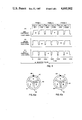
- FIGS. 4A, 4B and 4C are respective video signal diagrams illustrating the operation of the printer shown in the Figures;
- FIG. 5 is a perspective view of the optical assembly and coupling shown in FIG. 2;
- FIGS. 6A and 6B are frontal views respectively of the exposure and viewer filter wheels shown in FIG. 2;
- FIGS. 7A and 7B are elevational views respectively showing the optical assembly in the viewing position and in the exposing position.
- NTSC NTSC color video signal
- NTSC the standard broadcast signal in the United States, Canada, Japan and other countries. It will be understood that the present invention may also be used with other broadcast standards such as the PAL and SECAM systems used in Europe and other parts of the world.
- NTSC NTSC system
- a single color image is represented by a color video signal constituting a frame of two interlaced odd and even fields.
- Each color field signal includes luminance and chrominace components which encode three concurrent primary color component signals (red, green and blue).
- the color video signal is broadcast at 30 frames or 60 fields per second.
- printer 10 includes a housing 11 having a front panel 12, a top panel 13, and a side panel 14 with a door 30 for inserting packs of self-processing photographic elements into printer 10. Not shown are another side panel, a bottom panel and a rear panel.
- Front panel 12 includes a print ejection slot 15, a "POWER” switch 16, a “PRINT” switch 17, a “READY” light 18, an “NTSC/RGB” switch 19, an "EXPOSURE NUMBER” dial 20 and a latch 21.
- a cover 22 with lip 22a is mounted on panel 12 and is movable between an open position (as shown in FIG. 1) and a closed position. When cover 22 is in the open position, a recessed panel 23 is accessible to an operator for viewing and adjusting an image.
- Panel 23 includes an image viewer 24 and adjustable controls 25, 26, 27, 28 and 29 (to be explained later).
- printer 10 includes a video signal circuit 31 which receives (by actuation of switch 19 on panel 12 in FIG. 1) either a composite color video signal having luminance and chrominance component video signals or an RGB component color video signal having three concurrent primary color signals constituting red (R), green (G), and blue (B) component video signals.
- the composite color video signal is illustratively described as being in the NTSC format which has a field frequency of sixty fields per second, or a frame frequency of thirty frames per second.
- video signal circuit 31 processes either a composite color video signal or an RGB component color video signal to provide a repetitive sequence of RGB primary color component video signals to a monochrome electronic display device such as a monochrome cathode ray tube (CRT) 32.
- the applied video signal is converted to a monochrome optical image which is displayed on the screen 33 of CRT 32.
- An exposure station 36 is located along a first (exposure) optical path 34 from CRT 32. Positioned at station 36 is a pack 37 of unexposed self-processing photographic elements 38.
- a first (exposure) color filter wheel 39 has (see FIG. 6A) a red filter 40, a green filter 41, and a blue filter 42.
- Filter wheel 39 is mounted for rotation on shaft 43 and is driven by a motor 44 to sequentially move filters 40, 41 and 42 into optical path 34 in synchronism with the field frequency of the color video signal.
- Monochrome images displayed on screen 33 of CRT 32 are filtered by filters 40, 41 and 42 to produce color images projected to station 36 by projection lens 35.
- Printer 10 also has a viewing station 45 at which an operator may view an image prior to making a print.
- Viewing station 45 includes a second (viewer) filter wheel 46 mounted on shaft 47 and driven by motor 48.
- Filter wheel 46 is similar in construction to filter wheel 39 and includes respective red, green and blue filters 49, 50 and 51 (see FIG. 6B) which are sequentially movable into a second (viewer) optical path 52 from CRT 32 to viewer 24.
- a mirror assembly 53 which includes mirrors 54 and 55, is movable between a position (as shown in solid lines in FIG. 2) which is out of the exposure optical path 34 and a position (as shown in dashed lines in FIG. 2) intercepting optical path 34 and establishing viewer optical path 52.
- cover 22 is movable between a closed position (as shown in solid lines in FIG. 2) in which the viewer 24 is covered, and an open position (as shown in dashed lines in FIG. 2), in which the viewer 24 is uncovered so that an image displayed on CRT 32 may be viewed by an operator.
- cover 22 is opened, mirror assembly 53 is moved by coupling 56 into optical path 34.
- lip 22a of cover 22 contacts finger 56a of coupling 56 to move mirror assembly 53 out of optical path 34 to permit printing of the image produced by CRT 32.
- optical assembly 53 is in the viewing position and door 22 is open.
- Optical assembly 53 includes a housing 90 having a back wall 92, side walls 102 and 104, front wall 106 with viewing window 108 and sloping bottom wall 110 which supports mirror 54.
- Wall 102 has an opening 112 which faces face 33 of CRT 32.
- Housing 90 is slidably mounted on rod 114 by means of guides 116 and 118.
- Coupling 56 includes a lever 120 which is rotatably mounted on pivot 121 and interacting lever 122 which is rotatably mounted on pivot 123.
- Lever 120 has an upwardly extending arm 124 having finger 56a and a rearwardly extending arm 126 which is attached to fixed post 128 by means of spring 130.
- Lever 122 includes arm 136 having a member 138. Member 138 engages a member 140 extending from the wall 104 of housing 90.
- a spring 142 extends between member 138 and extension 144 of guide 116 and biases members 138 and 140 together.
- a pin 146 extends from arm 126 into engagement with spring 148 coiled about pivot 123. End 150 of spring 148 engages tab 152 of lever 122.
- Printer 10 (FIG. 2) includes a shutter 58 movable into and out of optical path 34 by means of solenoid 60.
- a print eject assembly includes a pusher arm 62 actuated by a solenoid 64 and a pair of processing and eject rollers 66 and 68 rotatably actuated by motor 70.
- Printer 10 also includes a detector 72 for detecting when optical assembly 53 is out of path 34 (which indicates cover 22 is closed). Operation of printer 10 is controlled by microprocessor control 74 which includes a microprocessor (such as the INTEL 8051), programming of which is well known to those skilled in the art.
- microprocessor control 74 which includes a microprocessor (such as the INTEL 8051), programming of which is well known to those skilled in the art.
- Video signal circuit 31 is shown in greater detail in FIG. 3.
- a composite color video signal received by video signal circuit 31 is applied to luminance (Y) processing circuit (Y PROC.) 80 and chrominance (C) processing circuit (C PROC.) 82.
- Circuits 80 and 82 respectively separate the Y and C component signals from the composite video signal.
- the luminance and chrominance signals are applied to RGB decode and processing circuit (RGB PROC.) 84 which decodes concurrent red (R), green (G) and blue (B) color component signals from the luminance and chrominance component signals.
- Circuit 84 also processes the R G B signals and applies them to gate 86.
- Gate 86 is controlled by microprocessor control 74 to select one of the three concurrent R, G or B component signals applied to it. The selected color component signal is then applied to a black and white processing circuit 88 before application to CRT 32.
- the operator controls on sub-panel 23 include control 25 and control 26 which respectively control the color saturation and hue of the chrominance signal processed by circuit 82; a control 27 which controls the detail of the luminance signal processed by circuit 80 and controls 28 and 29 which control the black and white levels of the signal processed by circuit 88 before being applied to the CRT 32.
- video signal circuit 31 is described in greater detail in cross-referenced, copending U.S. patent application Ser. No. 776,236, entitled WHITE COMPENSATION CIRCUIT FOR A COLOR VIDEO PRINTER and cross-referenced, copending U.S. patent application Ser. No. 776,231, entitled VIDEO SIGNAL PROCESSING CIRCUIT FOR A COLOR VIDEO PRINTER.
- each of wheels 39 and 46 are rotated at twenty revolutions per second.
- the rotational speed of wheels 39 and 46 are respectively sensed by detectors 94 and 96 (FIG. 2) detecting identifying marks 98 and 100 respectively on wheels 39 and 46.
- marks 98 and 100 also indicate the positioning of the red filters 40 and 49 in optical paths 34 and 52.
- Control 74 also applies power to CRT 32 to warm it up. After the CRT 32 is warmed up, a "READY" light 18 on panel 12 (FIG. 1) is turned on indicating to the operator that printer 10 is ready to make a photographic copy of a color video signal.
- control 74 actuates solenoid 60 to move shutter 58 out of exposure optical path 34.
- control 74 turns CRT 32 on and actuates gate 86 (FIG. 3) of video signal circuit 31 to select the red component video signal to be applied to CRT 32.
- CRT 32 converts the video signal to a monochrome optical image on screen 33 which is converted to a red optical image by red filter 40 (FIG. 6A).
- the red optical image is projected along path 34 by lens 35 to exposure station 36 to expose a self-processing photographic element 38 positioned at station 36.
- control 74 actuates gate 86 to sequentially select the corresponding green and blue component video signals to be applied to CRT 32. This sequence is repeated for another sequence of red, green and blue fields.
- a photographic element 38 is exposed to six color field images in the sequence red, green, blue, red, green, blue field images.
- FIG. 4 The sequence of exposure of element 38 is illustrated in FIG. 4. As shown, concurrent red (R), green (G) and blue (B) component video signals are applied by circuit 84 to gate 86 for a duration of three frames or six fields of color video signals. Each frame includes interlaced odd and even fields. Microprocessor control 74 is programmed to actuate gate 86 to select only one color component signal from each field of three concurrent color component signals for application to CRT 32. In FIG. 4, the selected color component signal is indicated by "*".
- control 74 turns off CRT 32 and actuates solenoid 60 to close shutter 58.
- Photographic element 38 is ejected from exposure station 36 by actuation of solenoid 64 to cause pusher rod 62 to move element 38 out of pack 37 into the nip of rollers 66 and 68 (dashed lines in FIG. 2) which are rotated by motor 70.
- rollers 66, 68 rupture a pod of processing chemicals made integral with element 38 and spread the chemicals uniformly over the exposed image-forming area of element 38.
- Element 38 self-processes to a finished photographic print outside of printer 10.
- a particularly exemplary photographic element which may be used in printer 10 is the "Trimprint" R instant film pack sold by the Eastman Kodak Company, Rochester, N. Y.
- printer 10 After ejection of an exposed self-processing photographic element from exposure station through slot 15 in panel 12 (FIG. 1), printer 10 is ready to make another copy.
- Spring 132 of pack 37 urges an unexposed photographic element 38 into exposure station 36.
- the operator desires to make adjustments to the characteristics of the color image to be copied, he/she opens cover 22 to gain access to viewer 24 and image controls 25-29 (FIG. 1). As described above, optical assembly 53 is moved into optical path 34 by coupling 56 to establish viewing optical path 52 to viewer 24 (FIG. 2). After detecting red filter mark 100 of the viewer filter wheel 46, microprocessor control 74 turns on CRT 32 and actuates gate 86 to gate through to CRT 32, repetitive sequences of red, green and blue component video signals. Since viewer filter wheel 46 is synchronized with the field frequency of the incoming color video signal, the operator views the same color image that a photographic element 38 will be exposed to. By adjusting controls 25-29 on panel 12 (FIG. 1) the operator can change the color, hue, detail, black and white level characteristics of the color video image to be copied.
- Coupling 56 for actuating optical assembly 53 has been described as a specific mechanical arrangement, it will be appreciated that other mechanical arrangements known to those skilled in the art may also be used. Coupling 56 may also comprise electromechanical and electronic arrangements for effecting movement of optical assembly 53 between its viewing and exposing positions.
Landscapes
- Engineering & Computer Science (AREA)
- Multimedia (AREA)
- Signal Processing (AREA)
- Physics & Mathematics (AREA)
- General Physics & Mathematics (AREA)
- Projection-Type Copiers In General (AREA)
- Control Of Exposure In Printing And Copying (AREA)
- Color Image Communication Systems (AREA)
Priority Applications (4)
| Application Number | Priority Date | Filing Date | Title |
|---|---|---|---|
| US06/776,233 US4695902A (en) | 1985-09-16 | 1985-09-16 | Color video printer includes a color viewer and image adjustment controls which are inhibited during exposure |
| JP61504875A JPS63500980A (ja) | 1985-09-16 | 1986-09-04 | カラ−ビデオプリンタ用カラ−ビュ−ア |
| EP86905611A EP0237547A1 (en) | 1985-09-16 | 1986-09-04 | Color viewer for a color video printer |
| PCT/US1986/001809 WO1987001892A1 (en) | 1985-09-16 | 1986-09-04 | Color viewer for a color video printer |
Applications Claiming Priority (1)
| Application Number | Priority Date | Filing Date | Title |
|---|---|---|---|
| US06/776,233 US4695902A (en) | 1985-09-16 | 1985-09-16 | Color video printer includes a color viewer and image adjustment controls which are inhibited during exposure |
Publications (1)
| Publication Number | Publication Date |
|---|---|
| US4695902A true US4695902A (en) | 1987-09-22 |
Family
ID=25106835
Family Applications (1)
| Application Number | Title | Priority Date | Filing Date |
|---|---|---|---|
| US06/776,233 Expired - Fee Related US4695902A (en) | 1985-09-16 | 1985-09-16 | Color video printer includes a color viewer and image adjustment controls which are inhibited during exposure |
Country Status (4)
| Country | Link |
|---|---|
| US (1) | US4695902A (ja) |
| EP (1) | EP0237547A1 (ja) |
| JP (1) | JPS63500980A (ja) |
| WO (1) | WO1987001892A1 (ja) |
Cited By (4)
| Publication number | Priority date | Publication date | Assignee | Title |
|---|---|---|---|---|
| US4999791A (en) * | 1988-12-23 | 1991-03-12 | Schumann Robert W | Computer graphics color film recording method and apparatus |
| US5018085A (en) * | 1988-06-16 | 1991-05-21 | Hallmark Cards, Inc. | Color printing system usable for reproduction of computer-generated images |
| US5361146A (en) * | 1992-07-16 | 1994-11-01 | Fuji Photo Film Co., Ltd. | Liquid crystal display panel monitor |
| US5843615A (en) * | 1995-12-04 | 1998-12-01 | Avery Dennison Corporation | Image-recording technology |
Families Citing this family (3)
| Publication number | Priority date | Publication date | Assignee | Title |
|---|---|---|---|---|
| JPH02267537A (ja) * | 1989-04-10 | 1990-11-01 | Brother Ind Ltd | 画像露光装置 |
| GB2304253A (en) * | 1995-08-07 | 1997-03-12 | Video Technologies Inc | Television receiver with printer |
| GB2361598A (en) * | 2000-03-30 | 2001-10-24 | Elecvision Inc | Printing apparatus for electric images |
Citations (15)
| Publication number | Priority date | Publication date | Assignee | Title |
|---|---|---|---|---|
| US2295628A (en) * | 1940-11-13 | 1942-09-15 | Gen Aniline & Film Corp | Apparatus for the reversal of color negatives |
| US2731511A (en) * | 1950-11-28 | 1956-01-17 | Wiesen Bernard | Color television systems |
| US2995619A (en) * | 1958-06-03 | 1961-08-08 | Freeman Samuel | System of television transmission and photographic reproduction of the televised image |
| US3644664A (en) * | 1970-03-16 | 1972-02-22 | Eastman Kodak Co | Correction level adjustment for video negative analyzer |
| US3684365A (en) * | 1971-07-08 | 1972-08-15 | Varian Associates | Display tube camera system allowing an observer an unobstructed view of the display |
| US3897250A (en) * | 1972-05-15 | 1975-07-29 | Wagner & Cie Ag | Method and apparatus for exposing a light-sensitive layer |
| US3934081A (en) * | 1973-03-31 | 1976-01-20 | Schumacher Ernst E | Method and apparatus for improving photomechanical reproduction by contrast decrease |
| US3961366A (en) * | 1972-05-15 | 1976-06-01 | Wagner & Cie Ag | Apparatus for exposing a light-sensitive layer |
| US4191962A (en) * | 1978-09-20 | 1980-03-04 | Bohumir Sramek | Low cost multi-channel recorder and display system for medical and other applications |
| US4231061A (en) * | 1979-04-09 | 1980-10-28 | Samuel Freeman | Instant color slide recorder of CRT image |
| US4339769A (en) * | 1979-06-25 | 1982-07-13 | Toppan Printing Co., Ltd. | Photography apparatus for television picture |
| EP0070677A2 (en) * | 1981-07-14 | 1983-01-26 | Dai Nippon Printing Co., Ltd. | Video printing apparatus |
| US4373156A (en) * | 1980-04-11 | 1983-02-08 | Bell & Howell Company | Apparatus and method for producing rapid, high resolution hard color copies from computer-based graphics and digital image processing systems |
| US4396279A (en) * | 1980-10-31 | 1983-08-02 | Fuji Photo Film Co., Ltd. | Trimming condition observing device in picture printer |
| US4566035A (en) * | 1983-03-18 | 1986-01-21 | Advanced Technology Laboratories, Inc. | CRT Monitor with built-in camera |
-
1985
- 1985-09-16 US US06/776,233 patent/US4695902A/en not_active Expired - Fee Related
-
1986
- 1986-09-04 JP JP61504875A patent/JPS63500980A/ja active Pending
- 1986-09-04 WO PCT/US1986/001809 patent/WO1987001892A1/en not_active Ceased
- 1986-09-04 EP EP86905611A patent/EP0237547A1/en not_active Withdrawn
Patent Citations (16)
| Publication number | Priority date | Publication date | Assignee | Title |
|---|---|---|---|---|
| US2295628A (en) * | 1940-11-13 | 1942-09-15 | Gen Aniline & Film Corp | Apparatus for the reversal of color negatives |
| US2731511A (en) * | 1950-11-28 | 1956-01-17 | Wiesen Bernard | Color television systems |
| US2995619A (en) * | 1958-06-03 | 1961-08-08 | Freeman Samuel | System of television transmission and photographic reproduction of the televised image |
| US3644664A (en) * | 1970-03-16 | 1972-02-22 | Eastman Kodak Co | Correction level adjustment for video negative analyzer |
| US3684365A (en) * | 1971-07-08 | 1972-08-15 | Varian Associates | Display tube camera system allowing an observer an unobstructed view of the display |
| US3897250A (en) * | 1972-05-15 | 1975-07-29 | Wagner & Cie Ag | Method and apparatus for exposing a light-sensitive layer |
| US3961366A (en) * | 1972-05-15 | 1976-06-01 | Wagner & Cie Ag | Apparatus for exposing a light-sensitive layer |
| US3934081A (en) * | 1973-03-31 | 1976-01-20 | Schumacher Ernst E | Method and apparatus for improving photomechanical reproduction by contrast decrease |
| US4191962A (en) * | 1978-09-20 | 1980-03-04 | Bohumir Sramek | Low cost multi-channel recorder and display system for medical and other applications |
| US4231061A (en) * | 1979-04-09 | 1980-10-28 | Samuel Freeman | Instant color slide recorder of CRT image |
| US4339769A (en) * | 1979-06-25 | 1982-07-13 | Toppan Printing Co., Ltd. | Photography apparatus for television picture |
| US4373156A (en) * | 1980-04-11 | 1983-02-08 | Bell & Howell Company | Apparatus and method for producing rapid, high resolution hard color copies from computer-based graphics and digital image processing systems |
| US4396279A (en) * | 1980-10-31 | 1983-08-02 | Fuji Photo Film Co., Ltd. | Trimming condition observing device in picture printer |
| EP0070677A2 (en) * | 1981-07-14 | 1983-01-26 | Dai Nippon Printing Co., Ltd. | Video printing apparatus |
| US4468693A (en) * | 1981-07-14 | 1984-08-28 | Dai Nippon Printing Co., Ltd. | Video printing apparatus |
| US4566035A (en) * | 1983-03-18 | 1986-01-21 | Advanced Technology Laboratories, Inc. | CRT Monitor with built-in camera |
Cited By (4)
| Publication number | Priority date | Publication date | Assignee | Title |
|---|---|---|---|---|
| US5018085A (en) * | 1988-06-16 | 1991-05-21 | Hallmark Cards, Inc. | Color printing system usable for reproduction of computer-generated images |
| US4999791A (en) * | 1988-12-23 | 1991-03-12 | Schumann Robert W | Computer graphics color film recording method and apparatus |
| US5361146A (en) * | 1992-07-16 | 1994-11-01 | Fuji Photo Film Co., Ltd. | Liquid crystal display panel monitor |
| US5843615A (en) * | 1995-12-04 | 1998-12-01 | Avery Dennison Corporation | Image-recording technology |
Also Published As
| Publication number | Publication date |
|---|---|
| EP0237547A1 (en) | 1987-09-23 |
| JPS63500980A (ja) | 1988-04-07 |
| WO1987001892A1 (en) | 1987-03-26 |
Similar Documents
| Publication | Publication Date | Title |
|---|---|---|
| US4688104A (en) | Apparatus for producing a full resolution color photographic copy of a color video signal | |
| US4603966A (en) | Film video player/printer with cropping control | |
| US4873576A (en) | Camera equipped with a television set | |
| US5335082A (en) | Method and apparatus for using monochrome images to form a color image | |
| US6995793B1 (en) | Video tap for a digital motion camera that simulates the look of post processing | |
| US4339769A (en) | Photography apparatus for television picture | |
| JPS61224792A (ja) | ビデオトリミング装置 | |
| US4695902A (en) | Color video printer includes a color viewer and image adjustment controls which are inhibited during exposure | |
| US4454532A (en) | White balance control for color video camera | |
| EP0386129B1 (en) | Enlarging photographic printer | |
| US4694356A (en) | Modification of color component video signals to compensate for decreasing white sensitivity of photographic element | |
| US4685000A (en) | Inhibition of exposure in a video printer upon loss of color filter sync | |
| WO1987001892A2 (en) | Color viewer for a color video printer | |
| US5294993A (en) | Method and apparatus for using monochrome images to form a color image | |
| US4694355A (en) | Black and white level adjustment and normalization circuit for a color video printer | |
| US4310848A (en) | Colorimetric evaluation of photographic film | |
| US3591268A (en) | Method and apparatus for optically recording color picture information | |
| WO2000010054A1 (en) | Video-to-film transfer process | |
| JPS6328418Y2 (ja) | ||
| JPH07113733B2 (ja) | 写真撮影システム | |
| JPS62115430A (ja) | 主要被写体指示装置 | |
| JP2579168Y2 (ja) | 映像複写装置 | |
| JPS63311338A (ja) | カラ−写真焼付装置 | |
| JPS61224793A (ja) | 写真のビデオトリミング装置 | |
| Strain | The shape of screens to come |
Legal Events
| Date | Code | Title | Description |
|---|---|---|---|
| FEPP | Fee payment procedure |
Free format text: PAYOR NUMBER ASSIGNED (ORIGINAL EVENT CODE: ASPN); ENTITY STATUS OF PATENT OWNER: LARGE ENTITY Free format text: PAYER NUMBER DE-ASSIGNED (ORIGINAL EVENT CODE: RMPN); ENTITY STATUS OF PATENT OWNER: LARGE ENTITY |
|
| AS | Assignment |
Owner name: EASTMAN KODAK COMPANY, ROCHESTER, NEW YORK, A NEW Free format text: ASSIGNMENT OF ASSIGNORS INTEREST.;ASSIGNOR:WOLCOTT, DANA W.;REEL/FRAME:004735/0924 Effective date: 19850912 |
|
| FPAY | Fee payment |
Year of fee payment: 4 |
|
| REMI | Maintenance fee reminder mailed | ||
| LAPS | Lapse for failure to pay maintenance fees | ||
| FP | Lapsed due to failure to pay maintenance fee |
Effective date: 19950927 |
|
| STCH | Information on status: patent discontinuation |
Free format text: PATENT EXPIRED DUE TO NONPAYMENT OF MAINTENANCE FEES UNDER 37 CFR 1.362 |