US4686365A - Fourier transform ion cyclothon resonance mass spectrometer with spatially separated sources and detector - Google Patents
Fourier transform ion cyclothon resonance mass spectrometer with spatially separated sources and detector Download PDFInfo
- Publication number
- US4686365A US4686365A US06/685,811 US68581184A US4686365A US 4686365 A US4686365 A US 4686365A US 68581184 A US68581184 A US 68581184A US 4686365 A US4686365 A US 4686365A
- Authority
- US
- United States
- Prior art keywords
- ions
- mass
- signal
- region
- ion
- Prior art date
- Legal status (The legal status is an assumption and is not a legal conclusion. Google has not performed a legal analysis and makes no representation as to the accuracy of the status listed.)
- Expired - Lifetime
Links
Images


Classifications
-
- G—PHYSICS
- G01—MEASURING; TESTING
- G01N—INVESTIGATING OR ANALYSING MATERIALS BY DETERMINING THEIR CHEMICAL OR PHYSICAL PROPERTIES
- G01N24/00—Investigating or analyzing materials by the use of nuclear magnetic resonance, electron paramagnetic resonance or other spin effects
- G01N24/14—Investigating or analyzing materials by the use of nuclear magnetic resonance, electron paramagnetic resonance or other spin effects by using cyclotron resonance
-
- H—ELECTRICITY
- H01—ELECTRIC ELEMENTS
- H01J—ELECTRIC DISCHARGE TUBES OR DISCHARGE LAMPS
- H01J49/00—Particle spectrometers or separator tubes
- H01J49/26—Mass spectrometers or separator tubes
- H01J49/34—Dynamic spectrometers
- H01J49/36—Radio frequency spectrometers, e.g. Bennett-type spectrometers, Redhead-type spectrometers
- H01J49/38—Omegatrons ; using ion cyclotron resonance
Definitions
- This invention relates to mass spectroscopy in general, and more particularly to an improved method and apparatus for carrying out ion cyclotron resonance spectroscopy.
- MS mass spectrometry
- ICR ion cyclotron resonance
- the observable electrical signal arising from the motions of an ensemble of trapped ions of a single mass would be an exponentially-decaying sine wave (the rate of decay is determined by the frequency of collision between ionic and neutral molecules).
- the ionic motions are reflected in a complex fluctuating signal made up of interferring sine waves of different frequencies and phases.
- This time-domain transient signal is often called an "interferogram" or simply a "transient.”
- the individual frequency components of the interferogram are rendered observable by Fourier transformation, which is facilitated by digitizing the interferogram and storing its discrete binary representation in the memory of a digital computer where it can be processed numerically.
- the resolution and accuracy obtainable in the ICR experiment are limited by different factors, depending on the nature of the sample.
- the mass resolution is limited by the size of the digital memory available for storage of the interferogram, whereas, with chromatographic sources, the resolution is limited by the quality of the vacuum attainable in the mass analyzer. In either case, the accuracy of the measured masses is limited by the accuracy of the calibration function.
- the ion source and detection regions must be spatially separated and differentially pumped to achieve the required ultra-high vacuum in the analyzer region. If satisfactory differential pumping can be achieved, the problem is reduced to one of transporting the ions to, and trapping them in, the ICR mass-analyzer cell.
- the method and apparatus of the present invention provides mechanical and electronic means to separate spatially the sample-introduction and ionization steps from the mass analysis step, thereby facilitating the interfacing of gas and liquid chromatographic sample-sources and implementation of several modern ionization techniques, and includes electronic means to improve the dynamic range, resolution, accuracy, and speed of the ionic mass measurement.
- the major improvement over prior art mass spectrometers arises in the use of electrostatic lenses for the transportation of ions from the sample-injection/ion-source region and that of the mass analyzer.
- electrostatic lenses are preferred, and why the use of quadrupole rods imposes unnecessary limitations on the performance of the spectrometer.
- the system of electrostatic lenses described herein produces a tightly collimated ion beam focused along the principal axis of the magnetic field, which provides the most direct trajectory.
- the trajectory of an ion within an RF quadrupolar field is circuitous and the longer path length increases the probability of reactive collisions.
- the ions leaving the quadrupole rods have high velocities and widely diverging trajectories, making trapping in the ICR cell difficult at best.
- a vacuum chamber comprising three differentially-pumped regions is used to contain a versatile inlet system and ion source, an ion-optics system for the transportation of ions to the analyzer region, and an ICR ultra-high-resolution mass-analyzer.
- the ICR cell is situated in the homogeneous field of a large-bore cryogenic superconducting magnet.
- the high magnetic field of the cryogenic magnet is desirable since resolution improves and the upper mass limit is extended with increasing field strength.
- Samples are introduced into an ion source in the first vacuum chamber at a pressure of ⁇ 10 -3 torr, where they are volatilized and ionized by one of several methods: electron impact (EI), chemical ionization (CI), fast atom bombardment (FAB), or laser ionization (LI).
- EI electron impact
- CI chemical ionization
- FAB fast atom bombardment
- LI laser ionization Due to the solenoidal geometry of the cryogenic magnet, the ion source must be located about 1.5 meters from the ICR cell, and a system of electrostatic lenses is used to transport the ions over this distance.
- the ions are extracted from the source by an electrostatic lens and moved to the second, differentially-pumped chamber at a pressure of ⁇ 10 -6 torr, where they enter a low resolution mass-filter (a short RF quadrupole operated usually in the "RF only" mode, where it acts as a high-pass mass filter) to discriminate against unwanted low-mass ions (e.g. reagent or carrier gas ions), and to provide single ion monitoring capability.
- the mass filter can be disabled electronically in certain experiments, without degradation of transmission efficiency.
- the ions leaving the mass filter are accelerated and focused into a tightly collimated beam, which is steered by electrostatic deflector plates through the orifice between the second and third vacuum chambers.
- the ions entering the third vacuum region at a pressure of ⁇ 10 -9 torr, are refocused by an electrostatic retardation lens, wherein they are decelerated to almost thermal velocity prior to entering the ICR cell.
- This scheme produces a tightly collimated ion beam moving close to the Z-axis of the magnet to minimize Lorentz forces (the vector cross product between the velocity V and the magnetic field B) acting on the ions.
- the initial acceleration of the ions in the inhomogeneous magnetic field and final deceleration in the homogeneous field are used to overcome the reflection phenomenon associated with charged particles moving in a magnetic field gradient (See the Jackson text cited below).
- Magnetic reflection occurs when the ratio of the perpendicular to the parallel components of the velocity exceeds a threshhold value. Since the perpendicular (X and Y) components of the velocity are determined by the thermal energy of the ions, magnetic reflection can be overcome simply by making the Z-component of the velocity sufficiently large.
- high velocity ions are not easily trapped in the ICR cell and a retardation lens must be provided to decelerate the ions as they enter the homogeneous region of the field.
- the need to generate a discrete digital representation of the measured signal causes limitations in dynamic range (the ratio of the largest to the smallest signal that can be represented numerically), in resolution, and in mass accuracy.
- dynamic range the ratio of the largest to the smallest signal that can be represented numerically
- resolution the resolution
- mass accuracy the required dynamic range can exceed one million.
- available analog-to-digital converters of sufficient speed limit the dynamic range to a few thousand. Therefore, electronic circuitry was devised to overcome this limitation and expand the dynamic range to the natural limits imposed by physics of the ion trap.
- the discrete representation of the ICR signal causes difficulty in measuring the exact mass because the frequency corresponding to a given mass may fall between two data points. This problem can be minimized by the use of a very large digital memory, and interpolation algorithms to calculate the accurate mass.
- the illustrated embodiment of the Fourier transform ICR spectrometer described herein provides the benefits of solid probe, as well as gas and liquid chromatographic inlets, while providing extremely high resolution and mass accuracy possible only with the ICR method of mass analysis. Furthermore, with the inclusion of several volatilization and ionization methods (EI, CI, FAB and LI), and novel electronic means to improve digital resolution and dynamic range, this invention constitutes an advance in the technology of mass spectroscopy, as well as ion cyclotron resonance spectroscopy, and satisfies a need which exists in the art.
- EI, CI, FAB and LI volatilization and ionization methods
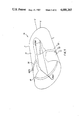
- FIG. 1 is a schematic illustration of an ion cyclotron resonance (ICR) detection cell.
- FIG. 2 is a computer simulation of the trajectory of an ion of mass 100 amu guided by a radio frequency quadrupolar electric field into the bore of a 7 Tesla superconducting solenoidal magnet, shown in a three-dimensional view.
- FIG. 3 is a computer simulation of the trajectory of an ion of mass 100 amv moving into the bore of a 7 Tesla superconducting solenoidal magnet.
- FIG. 4 illustrates typical configurations for electrostatic lenses: (A) a three-element aperture lens; and (B) a three-element cylinder lens.
- FIG. 5 is computer simulations of ion trajectories through a three-element electrostatic cylinder lens in the absence of a magnetic field, shown in a three-dimensional cut-away view.
- FIG. 6 is computer simulations of ion trajectories through a three-element electrostatic cylinder lens in the presence of a magnetic field gradient increasing in the positive z-direction, shown in a three-dimensional cut-away view.
- FIG. 7 is a schematic illustration of one embodiment of the Fourier transform ion cyclotron resonance mass spectrometer, shown in a cross-sectional view.
- FIG. 8 is a schematic illustration of the sample inlet and ionization system.
- FIG. 9 is a block diagram of the interconnection of essential electronic components in the illustrated embodiment of the inventive apparatus.
- FIG. 10 is a diagram illustrating the timing of various events in the ion-trapping, excitation and acquisition sequence of a typical Fourier transform ion cyclotron resonance experiment. Representative durations for each of the events are given in the right-hand column.
- FIG. 11 is a block diagram for an automatic gain control (AGC) amplifier with a digital gain control element.
- AGC automatic gain control
- FIG. 1 An illustration of an ICR trapping cell is shown in FIG. 1. Illustrated are six plates, 11-16, arranged in pairs to form a cubical space comprising a trapping cell 19. Potentials are applied across the pairs of plates and a magnetic field B is provided in the directions of arrow 18. The static electrical potentials applied to the walls of the cell, in combination with the applied magnetic field, create forces which restrict the ion motions to the interior of the cell. The orbital motions of the ions can be accelerated to larger radii by the application of a radio frequency oscillating electric field, and these motions can be detected by the observation of electric currents ("image" currents) induced in the walls of the cell.
- image currents electric currents
- FIG. 2 illustrates the trajectory of an ion injected into a radio frequency quadrupolar electric field generated by rods 25-28 at a distance of one meter from the center of a 7 Tesla superconducting magnet.
- the principal axis of the magnetic field is along the z-direction of the reference frame and the field strength is maximum at position (0,0,0).
- the scale of the illustration is distorted to show sufficient detail.
- the magnetic field is weak and the ion is forced to undergo a complex oscillatory motion due to its interaction with the fluctuating electric field.
- the ion moves to stronger magnetic field strengths, its motion becomes orbital due to the domination of the magnetic interactions over the electric interactions.
- the frequency of the electric field is near a harmonic of the cyclotron frequency for the ion, the ion will be accelerated into a larger orbit and may collide with the quadrupole rods or be reflected away from the magnet.
- the initial velocity of the ion, its mass/charge ratio, the peak-to-peak voltage on the quadrupole rods, and its position in the magnetic field all affect the trajectory of the ion.
- FIG. 3 illustrates a computer simulation of the trajectory of an identical ion (same initial velocity, and position) moving parallel to the principal axis of a static magnetic field, with the quadrupolar electric field turned off.
- the quadrupole rods shown for comparison with FIG. 2, are inoperative.
- the principal axis of the magnetic field is along the z-direction of the reference frame and the field strength is maximum at position (0,0,0).
- the scale of the illustration is distorted to show sufficient detail.
- the generation of the collimated ion-beam accelerated along the principal axis of the magnetic field will provide a more direct and controllable pathway to the mass-analyzer.
- the magnetic field was approximated by numerical integration of the Biot-Savart equation (J. D. Jackson, Classical Electrodynamics, John Wiley & Sons, Inc., N.Y., 1975), and the quadrupolar electric field was calculated exactly.
- FIGS. 4A and B Examples of electrostatic lenses are shown in FIGS. 4A and B, wherein a three-element aperture (disc) lens made up of discs 30-32 and three-element cylinder lens are illustrated. More complex lenses can be constructed with additional elements. Adjustable electrical potentials V 1 , V 2 and V 3 are applied to the individual lens elements to determine the optical characteristics. Depending upon the physical geometry of the lens elements and the values of the electrical potentials applied to each element, electrostatic lenses V 1 , V 2 and V 3 will mimic a variety of optical lenses in their ability to focus diverging beams. Moreover, they can be made to accelerate, decelerate, or leave unchanged the velocity of an ion beam.
- V 1 , V 2 and V 3 will mimic a variety of optical lenses in their ability to focus diverging beams. Moreover, they can be made to accelerate, decelerate, or leave unchanged the velocity of an ion beam.
- an "einzel" lens The special case where the potentials on the outer elements, e.g., 30 and 31 or 35 and 37 are equal and the central element is held at a different potential is called an "einzel" lens.
- a detailed treatment of the design of electrostatic lenses is given in E. Harting and F. H. Read, Electrostatic Lenses, Elsevier Scientific Publishing Company, New York, 1976, although cases where magnetic fields are present are not discussed.
- the optical properties of a three-element einzel cylinder lens are calculated by numerical solution of the electrostatic boundary-value problem where the electric field obtained by differentiation of the computed potentials and the magnetic field is calculated as discussed previously.
- the trajectory of an ion beam through an einzel lens 39 is modified by the presence of a static magnetic field, as shown in FIGS. 5 and 6.
- Computer-simulated trajectories respectively in the absence and presence of a magnetic field are calculated for ions of mass 100 with a total energy of 40 eV.
- the initial position and trajectory of the ion beam is indicated by the arrow labeled "START.."
- the ion beam has initially a large radial component of velocity which is removed by its interaction with the inhomogeneous electric field within the lens.
- the Fourier transform ion cyclotron resonance mass spectrometer of the present invention is housed within a three-stage, differentially-pumped vacuum chamber, as shown in FIG. 7. Most of the vacuum-housing components were supplied by NOR-CAL Products Inc.
- the stainless-steel vacuum housing, 51 is assembled using three six-way tubular crosses 53 equipped with high-vacuum flanges and crushed-metal seals, and separated by 8" dia. tubular sections.
- a long tubular section 56 of the vacuum housing (5" dia.) is inserted into the 6" dia. bore of a cryogenic superconducting magnet (Oxford Instruments Inc.
- the three regions of the vacuum chamber, A, B and C, are differentially pumped by three cryogenic vacuum pumps, 63 (CTI Cryogenics model CT-8).
- Cryogenic pumps were selected because of their ability to operate in a magnetic field (unlike turbo-molecular pumps), high pumping speeds, low ultimate pressures, complete absence of contaminating materials such as pump oils, and their ability to cope with a high throughput of chromatographic gases and solvents.
- the roughing-pump system comprising venturi and sorption pumps is not shown in FIG. 7.
- Each of the three vacuum pumps can be isolated from the vacuum housing 1, by an associated gate valve 64 (VAT Inc. ultra-high vacuum valves series 10, 200 mm). Also, the ultra-high vacuum chamber, region C, can be isolated from the rest of the system by a gate valve 64a.
- VAT Inc. ultra-high vacuum valves series 10, 200 mm.
- the ultra-high vacuum chamber, region C can be isolated from the rest of the system by a gate valve 64a.
- the sample inlets (not shown in FIG. 7) for solid probe and chromatographic interfaces supply vaporized neutral molecules to the ion source 65, wherein the molecules are ionized either directly by an electron beam from the filament 67, (EI) or indirectly by chemical ionization (CI) using reagent-gas ions fed through inlet 71, or by a laser beam (LI) from Laser 73 or by fast-atom bombardment (FAB) through inlet 71, as illustrated by the sketch in FIG. 8.
- EI electron beam from the filament 67,
- CI chemical ionization
- LI laser beam
- FAB fast-atom bombardment
- a combined EI/CI ion source was constructed by modification of an Extranuclear Laboratories model E2-1000 ion source, wherein the radial electron beam was changed to an axial beam by relocation of the filament and repeller plate, and an aperture was made in the removable ion-volume cup to permit entry of the axial beam. Note that not all of the components shown are not connected or used in the spectrometer at the same time. Interchangeable ion sources are used to provide versatility in sample introduction and ionization.
- the ion extraction lens 66 transports the ions from the first vacuum chamber to the second, wherein the ions enter a low-resolution mass filter 68 (a short RF quadrupole), to remove undesired low-mass ions such as carrier gas and solvent ions from the chromatographs, or chemical ionization reagent gas ions.
- a low-resolution mass filter 68 a short RF quadrupole
- the presence of these low-mass ions would increase the space charge in the ICR mass-analyzer, which would degrade resolution and cause the measured cyclotron frequency to shift.
- ELFS Extranuclear Laboratories Field Separator, a leaky-dielectric device which causes gradual decay of the RF electric field near the rod-ends and complete blockage of DC electric fields, thereby collimating the emerging ions).
- the quadrupole filter is usually operated in the RF-only mode where it acts as a high-pass filter, although the RF/DC band-pass mode is available if needed for selective ion transmission.
- the quadrupole can also be disabled electronically for certain applications. It is noteworthy that the quadrupole filter is situated in a weak region ( ⁇ 0.001 Tesla) of the magnetic field, and that the ion traject
- An electrostatic three-element cylinder lens 69 provides focussing of the ion beam emerging from the quadrupole rods.
- Electrostatic steering plates 80 and 81 provide horizontal and vertical deflection of the beam, respectively, to maintain the position of the beam close to the principal axis of the magnetic field and to direct the beam through a second orifice 77 which supports the pressure-differential between the second and third vacuum chambers B and C.
- a grid tube 82 provides an equipotential flight path for the ion beam. It is a cylinder of fine wire mesh held at the electrical potential of the ion beam. Its function is to shield the beam from the influence of stray electric fields, such as those arising from the vacuum housing at ground potential, and provides lower restriction to pumping than could be achieved with a solid tube.
- a pair of electrostatic three-element cylinder lenses 83 and 85 sharing a common element in a second equipotential grid tube 84, provide additional acceleration and focussing of the ion beam to transport the ions over a distance of one meter in vacuum region C, against a large magnetic field gradient.
- a three-element aperture deceleration lens 86 slows the beam to almost thermal velocity prior to entering the ion trapping cell 87.
- the ICR cell 87 comprises six electrically-isolated metal plates forming the sides of a box, with attached wiring to supply adjustable DC voltages to the plates and to conduct the excitation and response signals. (See FIG. 1)
- the various electrical connections to the mass spectrometer are brought into the vacuum housing by ceramic high-vacuum feedthroughs (supplied by Ceramaseal Inc.).
- the ICR cell 87 When the ions are present in the ICR cell 87, the voltage on the end plates 55 and 56 is raised to about 1 Volt to prevent escape of the ions in the z-direction. The magnetic and electric fields induce cyclotron and magnetron motions, which prevent loss of ions in the X-Y plane. Thus, the ions are effectively trapped within the volume of the ICR cell 87, where they can be observed over relatively long periods of time.
- the ICR cell is supplied optionally with positive or negative direction (DC) voltages for trapping positive or negative ions, and a pulsed alternating voltage for the excitation of the ions.
- DC positive or negative direction
- CHIRP CHIRP excitation
- the so-called "CHIRP" excitation is a radio-frequency pulse in which the frequency is swept rapidly during the pulse over a range sufficient to excite the mass-range of interest. Excitation corresponds to acceleration of the ionic motions to larger radii.
- the amplitude and duration of the CHIRP pulse determine the radii of the "parking orbits", the orbits in which the coherent ion motions are observed.
- the ionic motions induce a minute fluctuating electric current (the "image” current, see Wilkins et al. and Smith et al. supra) to flow between the opposing side plates of the cell and through external electronic circuitry in which the current is amplified and detected.
- the amplified image current is digitized and stored in the memory of a digital computer, where the time-domain transient signal is Fourier transformed to reveal the characteristic cyclotron frequencies and the accurate masses of the ions.
- the electronic circuitry in the spectrometer can be subdivided into the categories of ion-optics and chromatograph controllers, excitation circuitry, detection circuitry, and digital processing equipment.
- the organization of the analog and ditgital circuitry is illustrated by the block diagram in FIG. 9.
- the ion source controller is an Extranuclear Laboratories model C50-IC Ionizer Controller and the quadrupole mass filter is regulated by a model C50-MS Mass Command Electronics from the same vendor.
- the ion optics controllers 91 are highly stable programmable DC power supplies that supply voltages to the individual elements of the various electrostatic lenses, and to the walls of the ICR cell 87.
- These voltages are controlled by a host computer 92 through an array of thirty-two 12-bit digital-to-analog converters 94 (Micro Networks Inc. model DAC-HK2).
- the DAC 94 outputs are amplified by high voltage operational amplifiers (Apex Microtechnology model PA08) to supply programmable voltages ranging between -140 and +140 volts.
- the individual lens voltages can be adjusted manually (to optimize ion transmission) by rotation of a digital shaft encoder (Litton Industries model 81 BI-256-5-1), or alternatively under the control of the host computer 92 using a simplex-optimization program.
- the host computer 92 is a MOTOROLA BENCHMARK-20TM 32-bit desk top computer based upon the MC68020 microprocessor and the MOTOROLA VERSAbusTM digital bus protocol.
- the spectrometer control software was written in PASCAL and MOTOROLA 68020 assembly language, using the VERSAdosTM real-time disc-operating system.
- the timing of various events in the spectrometer is determined by a programmable pulse generator 96, constructed using timers and counters available on standard large-scale integrated circuits.
- the pulse programmer is initialized by software in the host computer 92, and its carefully-timed output pulses are used to trigger several other electronic modules.
- a timing diagram for a typical FT-ICR experiment is shown in FIG. 10.
- the CHIRP excitation pulse originates in a digital frequency synthesizer 93 (Rockland model 5100), which can be swept at a predetermined rate between accurately known frequency limits, and programmed in amplitude, using the synthesizer programmer 100 [SPG].
- the synthesizer programmer 100 fabricated from standard integrated circuits, is in turn controlled by the host computer 92, which sets the operating parameters for the experiment, and is triggered by the pulse programmer 96.
- the CHIRP pulse is applied to a differential RF transmitter 102, which is connected to two of the opposing side plates of the ICR cell 87.
- the oscillating electric field produced by the CHIRP voltage accelerates ions of a given mass into coherent orbital motion, which can be detected by the image current induced in the side plates of the cell.
- the image current to be measured is very small, typically 10 -12 Amps, and the detection circuitry includes a resistance R through which the image current flows. Since the ICR cell 87 represents a high-impedance, mostly capacitive signal-source, the value of the resistance R must be very large (108M Ohms) to avoid loading the source.
- the capacitance C of the ICR cell is small (typically 0.2-0.5 pF) and the cutoff frequency of this RC circuit must be low enough to allow passage of the frequencies corresponding to the mass range of interest.
- the small voltage (typically 10 -4 volts) developed across the load resistance R is amplified by a differential pre-amplifier 104, which must have an extremely large input impedance, a low input capacitance, a low noise-figure and a wide band-width.
- a suitable field-effect transistor pre-amplifier was constructed with a gain of 300, a bandwidth of 1 kHz to 5 MHz, input capacitance of 0.25 pF, and impedance of 10 8 Ohms. Further amplification takes place in subsequent gain stages, as discussed below.
- Typical mass spectra contain a large range of peak-amplitudes, and chromatographic sources supply widely-varying sample sizes to the ion source.
- the ICR signal strength for a given ion can vary as much as one million fold. This imposes the requirement of an exceedingly large dynamic range on the main signal digitizer 106.
- the fast digitizers available currently are limited to a resolution of 12 bits at most, which corresponds to a dynamic range of only 4096:1. Consequently, a provision for controlled signal compression in the amplification chain is needed to increase the effective dynamic range of the digitization process.
- signal compression is achieved by means of a novel circuit for an automatic gain control amplifier 108, which ensures that the signal presented to the main digitizer 106 has ostensibly constant peak amplitude regardless of the number and type of ions in the ICF trapping cell (within certain practical limits), and that the dynamic range of the digitization process is maximized.
- an innovative automatic gain control circuit 108 incorporating a digital gain control element was designed and constructed.
- This module is shown as a functional block diagram in FIG. 11.
- This circuit contains a 20 dB signal amplifier 110 with differential inputs and outputs. One output is routed to a voltage controlled amplifier 112, and the other to a fast gated peak detector 114.
- Other circuit elements include a 12-bit analog-to-digital converter 116, a 12-bit digital-to-analog converter 118, TTL timing logic 120, and a signal output-amplifier 122.
- the gain of the VCA 112 must be adjustable over a range of at least 1000 by application of a DC control voltage.
- the gain of the VCA 112 must be highly linear over the range of the applied control voltage, which is not the case for a large class of monolithic AGC amplifiers used commonly in radio frequency circuits. Consequently, a true four-quadrant multiplier (MOTOROLA integrated circuit MC1594) was selected for the VCA function, providing a linear gain range of ca. 80 dB.
- the fast gated peak-detector 114 is also based on a monolithic integrated circuit, a Precision Monolithics Inc. PKD-01 configured for bipolar signals. This circuit produces a DC output voltage equal to the peak-to-peak amplitude of the alternating input signal. Provided that a small DC offset (ca. 100 mV) is applied to the input to ensure that the internal diodes always conduct, this peak detector has adequate linearity over the required range of RF signals.
- the peak detector 114 is gated on for 200 microseconds by the timing logic 120, immediately after the CHIRP excitation pulse ends. During this sampling period, the initial peak-to-peak amplitude of the transient ICR signal is measured, as indicated in timing diagram in FIG. 10.
- the proportional DC output voltage of the peak detector cannot be used directly to set the gain of the VCA 112 because of its small-but-significant drift during the period of the data acquisition.
- the required DC control voltage is inversely proportional to the peak amplitude and a divider circuit must be inserted between the gated peak detector 114 and the VCA 112. While in principle this could be done with analog circuit elements, it is more convenient and accurate to use digital circuitry.
- the DC output of gated peak detector 114 is digitized by the analog-to-digital converter 116 (Micro Networks Inc. integrated circuit ADC-80) in about 25 microseconds and the 12-bit binary representation of the peak amplitude is transferred to the host computer 92 for processing.
- the numerical scaling factor F s is evaluated by the computer and applied to the binary input of the 12-bit digital-to-analog converter 118, a Micro Networks Inc. integrated circuit DAC-HK.
- the analog voltage generated by the DAC 118 is scaled to the range 0-1 V by a potentiometer and applied to the X-input of the four-quadrant multiplier used as VCA 112.
- the ICR signal from differential amplifier is applied to the Y-input of the multiplier, which is configured for an overall gain of 10.
- the constant peak-amplitude signal from the multiplier (VCA 112) is applied to the output amplifier 122 (gain 100) which provides its output to a 50 Ohm line driver 123 for transmission to subsequent circuits.
- the signal scaling factor F s is stored along with each transient ICR signal in the host computer or on a magnetic disc, providing a means by which the true signal amplitudes can be restored during post-acquisition processing. Thus, accurate ion-chromatographs can still be generated.
- the timing for the AGC operation is controlled by internal TTL logic circuitry comprising a dual one-shot multivibrator 125 (74LS221), a D-type flip-flop 127 and an inverter 129.
- a positive-edge logic transition provided by the pulse programmer 96 of FIG. 9 starts a 200 microsecond period output on line 126 of one shot 125 to define the peak detector sampling period. At the end of this period, a 100 nanosecond trigger pulse on line 128 is generated to start the analog-to-digital converter 116.
- the end-of-conversion pulse (EOC) from ADC 116 is used to initiate data transfer to the host computer 92 and to reset the peak detector 114 in preparation for the next transient.
- a logic pulse from the host computer 92 latches the digital-to-analog converter 118.
- the critical time interval between the end of the CHIRP pulse and the start of main signal acquisition remains under the control of the pulse programmer 96 to ensure coherent signal averaging.
- the ICR signal can be mixed (heterodyned) with a reference signal from a local oscillator 135 in order to narrow the bandwidth of the observed frequencies, and hence increase the mass resolution of the experiments. Heterodyning produces both sum and difference frequencies, and the sum components are largely removed by the low pass filter 134.
- the filter can also be used independently of the mixer to remove high frequency noise components from the ICR signal.
- the ICR apparatus utilizes a 12-bit analog-to-digital converter 106 (Analog Devices Inc. MOD-1205) operating at frequencies up to 5 MHz.
- the conventional laboratory computer 92 is incapable of accepting information acquired at this high speed, as well as performing numerous control and processing functions in the spectrometer. Consequently, a highspeed (200 MB/sec burst rate), partitionable buffer memory 136 with add/subtract arithmetic capability (provided by an arithmetic logic unit 138, [ALU]) is used to accept the digitized interferogram and provide signal-averaging capability.
- This fast signal-averager was constructed by modification of WideWordTM bulk memory module manufactured by DATARAM Inc.
- At least a megaword of 32-bit memory is needed to provide sufficient digital resolution for analytical ICR experiments.
- a one-megaword memory would limit the mass resolution to 21,000 in a wide-range spectrum from mass 100 to 600 Daltons with data acquisition at a frequency of 2 MHz. To achieve higher resolution would require operation in the heterodyne (mixer) mode.
- the stringent data processing requirements of the experiment impose severe demands on the performance of the digital computer 92.
- the large data arrays must be Fourier transformed in a time on the order of one second, which is beyond the capability of the host computer. This short processing time is necessary to avoid loss of information from ephemeral chromatographic samples (capillary GC and microbore LC peaks have half widths of only a few seconds). Consequently, a pipelined vector arithmetic processor, also called an array processor, 190, must be used to achieve the required processing time.
- the host computer 92, the buffer memory 136, and the array processor 92 share a common bus 142 (based on the MOTOROLA VERSAbusTM protocol) to maximize the data throughput rate.
- the large data arrays acquired in these experiments require large mass-media storage.
- a 500 MByte magnetic disc 144 used for storage of unprocessed ICR interferograms can be filled completely in single chromatographic experiments.
- a smaller magnetic disc 146 provides storage for the frequency domain spectra because only information on ionic mass and amplitude need to be saved.
- Streaming magnetic tape 148 is used for archiving the spectra.
- Ion-molecule reactions can be studied in the ICR cell by injecting a pulse of a collision gas.
- this is achieved using a solenoidal pulsed gas valve 150, (Maxtec Inc. model MV-112 piezoelectric gas valve), which is actuated under the control of the pulse programmer 96.
- This valve 150 provides a momentary high pressure (ca. 10 -3 torr) of a reagent gas during which the ion-molecule reactions take place.
- the valve can be opened for as little as 0.001 s, and the high vacuum is quickly restored by the cryo-pump for low-pressure observation of the ICR signal of the product ions.
Landscapes
- Chemical & Material Sciences (AREA)
- Analytical Chemistry (AREA)
- Physics & Mathematics (AREA)
- High Energy & Nuclear Physics (AREA)
- Health & Medical Sciences (AREA)
- Life Sciences & Earth Sciences (AREA)
- Biochemistry (AREA)
- General Health & Medical Sciences (AREA)
- General Physics & Mathematics (AREA)
- Immunology (AREA)
- Pathology (AREA)
- Other Investigation Or Analysis Of Materials By Electrical Means (AREA)
- Analysing Materials By The Use Of Radiation (AREA)
- Investigating Or Analyzing Materials By The Use Of Electric Means (AREA)
Priority Applications (7)
| Application Number | Priority Date | Filing Date | Title |
|---|---|---|---|
| US06/685,811 US4686365A (en) | 1984-12-24 | 1984-12-24 | Fourier transform ion cyclothon resonance mass spectrometer with spatially separated sources and detector |
| AT85114933T ATE117127T1 (de) | 1984-12-24 | 1985-11-26 | Fourier-transformation-ionen-zyklotron-resonanz massenspektrometer mit räumlicher trennung von quellen und detektor. |
| DE3587975T DE3587975T2 (de) | 1984-12-24 | 1985-11-26 | Fourier-Transformation-Ionen-Zyklotron-Resonanz-Massenspektrometer mit räumlicher Trennung von Quellen und Detektor. |
| EP85114933A EP0185944B1 (fr) | 1984-12-24 | 1985-11-26 | Spectromètre de masse à résonance cyclotronique à technique de Fourier avec séparation spatiale des sources et du détecteur |
| CA000498225A CA1251871A (fr) | 1984-12-24 | 1985-12-20 | Spectrometre de masse a resonance cyclotronique d'ions a transformation de fourier a sources et a detecteur separes spatialement |
| KR1019850009732A KR940002515B1 (ko) | 1984-12-24 | 1985-12-23 | 공간적으로 분리된 이온원(源)과 검출기를 가진 푸우리에 변환 이온 사이클로트론 공명 질량 분석기 |
| JP60289560A JPH0746597B2 (ja) | 1984-12-24 | 1985-12-24 | 空間的に分離された源および検出器を有するフ−リエ変換イオンサイクロトロン共鳴質量分析計 |
Applications Claiming Priority (1)
| Application Number | Priority Date | Filing Date | Title |
|---|---|---|---|
| US06/685,811 US4686365A (en) | 1984-12-24 | 1984-12-24 | Fourier transform ion cyclothon resonance mass spectrometer with spatially separated sources and detector |
Publications (1)
| Publication Number | Publication Date |
|---|---|
| US4686365A true US4686365A (en) | 1987-08-11 |
Family
ID=24753764
Family Applications (1)
| Application Number | Title | Priority Date | Filing Date |
|---|---|---|---|
| US06/685,811 Expired - Lifetime US4686365A (en) | 1984-12-24 | 1984-12-24 | Fourier transform ion cyclothon resonance mass spectrometer with spatially separated sources and detector |
Country Status (7)
| Country | Link |
|---|---|
| US (1) | US4686365A (fr) |
| EP (1) | EP0185944B1 (fr) |
| JP (1) | JPH0746597B2 (fr) |
| KR (1) | KR940002515B1 (fr) |
| AT (1) | ATE117127T1 (fr) |
| CA (1) | CA1251871A (fr) |
| DE (1) | DE3587975T2 (fr) |
Cited By (65)
| Publication number | Priority date | Publication date | Assignee | Title |
|---|---|---|---|---|
| US4746802A (en) * | 1985-10-29 | 1988-05-24 | Spectrospin Ag | Ion cyclotron resonance spectrometer |
| US4818864A (en) * | 1986-08-14 | 1989-04-04 | Spectrospin Ag | Method for eliminating undesirable charged particles from the measuring cell of an ICR spectrometer |
| DE3733853A1 (de) * | 1987-10-07 | 1989-04-27 | Spectrospin Ag | Verfahren zum einbringen von ionen in die ionenfalle eines ionen-zyklotron-resonanz-spektrometers und zur durchfuehrung des verfahrens ausgebildetes ionen-zyklotron-resonanz-spektrometers |
| US4845364A (en) * | 1988-02-29 | 1989-07-04 | Battelle Memorial Institute | Coaxial reentrant ion source for surface mass spectroscopy |
| US4855593A (en) * | 1987-06-06 | 1989-08-08 | Spectrospin, Ag | Method for recording ICR mass spectra and ICR mass spectrometer designed for carrying out the said method |
| DE3821998A1 (de) * | 1988-06-30 | 1990-01-04 | Spectrospin Ag | Icr-ionenfalle |
| US4931640A (en) * | 1989-05-19 | 1990-06-05 | Marshall Alan G | Mass spectrometer with reduced static electric field |
| US4945234A (en) * | 1989-05-19 | 1990-07-31 | Extrel Ftms, Inc. | Method and apparatus for producing an arbitrary excitation spectrum for Fourier transform mass spectrometry |
| US4959543A (en) * | 1988-06-03 | 1990-09-25 | Ionspec Corporation | Method and apparatus for acceleration and detection of ions in an ion cyclotron resonance cell |
| WO1990015658A1 (fr) * | 1989-06-06 | 1990-12-27 | Viking Instruments Corp. | Systeme de spectrometrie de masse miniaturise |
| US4982088A (en) * | 1990-02-02 | 1991-01-01 | California Institute Of Technology | Method and apparatus for highly sensitive spectroscopy of trapped ions |
| US4990856A (en) * | 1989-01-23 | 1991-02-05 | Varian Associates, Inc. | Mass analysis apparatus and method |
| US4990775A (en) * | 1988-06-06 | 1991-02-05 | University Of Delaware | Resolution improvement in an ion cyclotron resonance mass spectrometer |
| US5013912A (en) * | 1989-07-14 | 1991-05-07 | University Of The Pacific | General phase modulation method for stored waveform inverse fourier transform excitation for fourier transform ion cyclotron resonance mass spectrometry |
| US5117108A (en) * | 1988-07-07 | 1992-05-26 | University Of Metz, Etablissement Public Caractere Scientifue Et Culturel | Laser microprobe interface for a mass spectrometer |
| US5179278A (en) * | 1991-08-23 | 1993-01-12 | Mds Health Group Limited | Multipole inlet system for ion traps |
| US5248883A (en) * | 1991-05-30 | 1993-09-28 | International Business Machines Corporation | Ion traps of mono- or multi-planar geometry and planar ion trap devices |
| US5302827A (en) * | 1993-05-11 | 1994-04-12 | Mks Instruments, Inc. | Quadrupole mass spectrometer |
| US5313061A (en) * | 1989-06-06 | 1994-05-17 | Viking Instrument | Miniaturized mass spectrometer system |
| US5539204A (en) * | 1995-02-10 | 1996-07-23 | Regents Of The University Of California | Mass spectrometer vacuum housing and pumping system |
| US5767512A (en) * | 1996-01-05 | 1998-06-16 | Battelle Memorial Institute | Method for reduction of selected ion intensities in confined ion beams |
| US5767506A (en) * | 1994-10-03 | 1998-06-16 | Coin Controls Ltd. | Optical coin sensing station having a passageway and beam splitters |
| US5777205A (en) * | 1995-09-29 | 1998-07-07 | Nikkiso Company Limited | Apparatus for analysis of mixed gas components |
| US5940281A (en) * | 1995-07-08 | 1999-08-17 | Robert Bosch Gmbh | Switched-mode power supply with magnetic flux density control |
| US5981946A (en) * | 1995-11-16 | 1999-11-09 | Leco Corporation | Time-of-flight mass spectrometer data acquisition system |
| US6053300A (en) * | 1995-07-14 | 2000-04-25 | Coins Controls Ltd. | Apparatus and method for determining the validity of a coin |
| WO2000024034A1 (fr) * | 1998-10-16 | 2000-04-27 | Siemens Applied Automation, Inc. | Vanne de fuite d'un spectrometre de masse pulse, a energie de fermeture regulee |
| US6119844A (en) * | 1995-04-07 | 2000-09-19 | Coin Controls Ltd. | Coin validation apparatus and method |
| US6225624B1 (en) * | 1998-10-16 | 2001-05-01 | Siemens Aktiengesellschaft | Precision pressure monitor |
| US6230869B1 (en) | 1996-01-23 | 2001-05-15 | Coin Controls Ltd | Coin validator |
| US6311820B1 (en) | 1996-06-05 | 2001-11-06 | Coin Control Limited | Coin validator calibration |
| US6414329B1 (en) * | 2000-07-25 | 2002-07-02 | Axcelis Technologies, Inc. | Method and system for microwave excitation of plasma in an ion beam guide |
| US6452168B1 (en) * | 1999-09-15 | 2002-09-17 | Ut-Battelle, Llc | Apparatus and methods for continuous beam fourier transform mass spectrometry |
| WO2002091426A1 (fr) * | 2001-05-03 | 2002-11-14 | The University Of Sydney | Spectrometre de masse |
| WO2003060945A1 (fr) * | 2002-01-09 | 2003-07-24 | Trustees Of Boston University | Appareil et procede permettant d'effectuer une spectrometrie de masse par resonance cyclotron des ions |
| US6661001B2 (en) * | 1995-10-25 | 2003-12-09 | Bruker Daltonics Inc. | Extended bradbury-nielson gate |
| US20040031918A1 (en) * | 2002-05-31 | 2004-02-19 | Schoen Alan E. | Mass spectrometer with improved mass accuracy |
| WO2004019003A2 (fr) * | 2002-08-23 | 2004-03-04 | Efeckta Technologies Corporation | Traitement des images de donnees de spectrometres de masse en vue de leur utilisation a de multiples resolutions |
| US6703628B2 (en) | 2000-07-25 | 2004-03-09 | Axceliss Technologies, Inc | Method and system for ion beam containment in an ion beam guide |
| US20040084613A1 (en) * | 2001-04-03 | 2004-05-06 | Bateman Robert Harold | Mass spectrometer and method of mass spectrometry |
| US20040195973A1 (en) * | 2002-06-26 | 2004-10-07 | Semequip, Inc. | Electron impact ion source |
| US20040211895A1 (en) * | 2000-11-29 | 2004-10-28 | Martin Green | Mass spectrometer and methods of mass spectrometry |
| US20040217284A1 (en) * | 2003-03-10 | 2004-11-04 | Thermo Finnigan, Llc | Mass spectrometer |
| US20050023487A1 (en) * | 2003-07-31 | 2005-02-03 | Wenzel Kevin W. | Method and system for ion beam containment using photoelectrons in an ion beam guide |
| US6858839B1 (en) * | 2000-02-08 | 2005-02-22 | Agilent Technologies, Inc. | Ion optics for mass spectrometers |
| US20050242280A1 (en) * | 2004-04-28 | 2005-11-03 | Bruker Daltonik Gmbh | Ion cyclotron resonance mass spectrometer |
| US20060071162A1 (en) * | 2004-10-01 | 2006-04-06 | Crawford Robert K | Mass spectrometer multipole device |
| US20070023630A1 (en) * | 2003-09-25 | 2007-02-01 | Robert Malek Etal | Method and apparatus for mass spectormetry |
| US20070114390A1 (en) * | 2004-08-26 | 2007-05-24 | Battelle Memorial Institute | Method and apparatus for enhanced sequencing of complex molecules using surface-induced dissociation in conjunction with mass spectrometric analysis |
| US20070114374A1 (en) * | 2005-10-20 | 2007-05-24 | Prest Harry F | Dynamic adjustment of ion monitoring periods |
| US20080029697A1 (en) * | 2006-07-12 | 2008-02-07 | Willis Peter M | Data Acquisition System and Method for a Spectrometer |
| US20080191130A1 (en) * | 2004-07-21 | 2008-08-14 | Micromass Uk Limited | Mass Spectrometer |
| US20090032696A1 (en) * | 2007-08-02 | 2009-02-05 | Dahl David A | Method and apparatus for ion cyclotron spectrometry |
| US20090242747A1 (en) * | 2008-04-01 | 2009-10-01 | Guckenberger George B | Removable Ion Source that does not Require Venting of the Vacuum Chamber |
| US20090258810A1 (en) * | 2008-04-01 | 2009-10-15 | Brian Xiaoqing Song | Gel automatic dishwashing detergent composition |
| US20100041583A1 (en) * | 2008-08-15 | 2010-02-18 | Jennifer Beth Ponder | Benefit compositions comprising polyglycerol esters |
| US20100156410A1 (en) * | 2006-01-16 | 2010-06-24 | National University Corporation Kobe University | Gas nuclear magnetic resonance apparatus |
| GB2466702A (en) * | 2008-12-30 | 2010-07-07 | Bruker Daltonik Gmbh | Excitation of ions in icr mass spectrometers |
| US20110049346A1 (en) * | 2009-08-25 | 2011-03-03 | Wells Gregory J | Methods and apparatus for filling an ion detector cell |
| US20110210731A1 (en) * | 2007-11-09 | 2011-09-01 | Vista Clara, Inc. | Multicoil low-field nuclear magnetic resonance detection and imaging apparatus and method |
| US8314379B2 (en) * | 2011-03-30 | 2012-11-20 | Krohne Messtechnik Gmbh | Drive unit for a synchronous ion shield mass separator |
| US20130174782A1 (en) * | 2012-01-09 | 2013-07-11 | Samsung Display Co., Ltd. | Low Temperature Deposition Apparatus |
| CN103262205A (zh) * | 2010-12-14 | 2013-08-21 | 塞莫费雪科学(不来梅)有限公司 | 离子检测 |
| US20130228681A1 (en) * | 2010-12-03 | 2013-09-05 | Korea Basic Science Institute | Fourier transform ion cyclotron resonance mass spectrometer and method for concentrating ions for fourier transform ion cyclotron resonance mass spectrometry |
| US11499764B2 (en) * | 2019-09-04 | 2022-11-15 | Quantinuum Llc | Cable management for cryogenic system |
Families Citing this family (6)
| Publication number | Priority date | Publication date | Assignee | Title |
|---|---|---|---|---|
| DE3515766A1 (de) * | 1985-05-02 | 1986-11-06 | Spectrospin AG, Fällanden, Zürich | Ionen-zyklotron-resonanz-spektrometer |
| US6815674B1 (en) * | 2003-06-03 | 2004-11-09 | Monitor Instruments Company, Llc | Mass spectrometer and related ionizer and methods |
| KR100824693B1 (ko) * | 2006-11-20 | 2008-04-24 | 한국기초과학지원연구원 | 혼성 이온 전송 장치 |
| KR100962550B1 (ko) * | 2007-12-31 | 2010-06-14 | 한국기초과학지원연구원 | 푸리에변환 이온 싸이클로트론 공명 질량분석기의 데이터획득 장치 및 그 방법 |
| DE102007063567A1 (de) | 2007-12-31 | 2009-07-09 | Daimler Ag | Verfahren zur Erzeugung einer nichtzylindrischen Bohrungsfläche in einem Werkstück durch Formhonen |
| JP7440475B2 (ja) * | 2021-11-05 | 2024-02-28 | 日本電子株式会社 | 高電圧増幅回路、及び分析装置 |
Citations (4)
| Publication number | Priority date | Publication date | Assignee | Title |
|---|---|---|---|---|
| US3922543A (en) * | 1972-10-17 | 1975-11-25 | Jesse L Beauchamp | Ion cyclotron resonance spectrometer and method |
| US3984681A (en) * | 1974-08-27 | 1976-10-05 | Nasa | Ion and electron detector for use in an ICR spectrometer |
| US4464570A (en) * | 1981-06-22 | 1984-08-07 | Martin Allemann | Method for ion cyclotron resonance spectroscopy |
| US4535235A (en) * | 1983-05-06 | 1985-08-13 | Finnigan Corporation | Apparatus and method for injection of ions into an ion cyclotron resonance cell |
Family Cites Families (3)
| Publication number | Priority date | Publication date | Assignee | Title |
|---|---|---|---|---|
| US3937955A (en) * | 1974-10-15 | 1976-02-10 | Nicolet Technology Corporation | Fourier transform ion cyclotron resonance spectroscopy method and apparatus |
| US3997846A (en) * | 1975-06-30 | 1976-12-14 | International Business Machines Corporation | Method and apparatus for electrostatic deflection of high current ion beams in scanning apparatus |
| US4581533A (en) * | 1984-05-15 | 1986-04-08 | Nicolet Instrument Corporation | Mass spectrometer and method |
-
1984
- 1984-12-24 US US06/685,811 patent/US4686365A/en not_active Expired - Lifetime
-
1985
- 1985-11-26 EP EP85114933A patent/EP0185944B1/fr not_active Revoked
- 1985-11-26 DE DE3587975T patent/DE3587975T2/de not_active Revoked
- 1985-11-26 AT AT85114933T patent/ATE117127T1/de not_active IP Right Cessation
- 1985-12-20 CA CA000498225A patent/CA1251871A/fr not_active Expired
- 1985-12-23 KR KR1019850009732A patent/KR940002515B1/ko not_active IP Right Cessation
- 1985-12-24 JP JP60289560A patent/JPH0746597B2/ja not_active Expired - Lifetime
Patent Citations (4)
| Publication number | Priority date | Publication date | Assignee | Title |
|---|---|---|---|---|
| US3922543A (en) * | 1972-10-17 | 1975-11-25 | Jesse L Beauchamp | Ion cyclotron resonance spectrometer and method |
| US3984681A (en) * | 1974-08-27 | 1976-10-05 | Nasa | Ion and electron detector for use in an ICR spectrometer |
| US4464570A (en) * | 1981-06-22 | 1984-08-07 | Martin Allemann | Method for ion cyclotron resonance spectroscopy |
| US4535235A (en) * | 1983-05-06 | 1985-08-13 | Finnigan Corporation | Apparatus and method for injection of ions into an ion cyclotron resonance cell |
Non-Patent Citations (4)
| Title |
|---|
| Heddle et al., The Focal Properties of Three Element Electrostatic Electron Lenses, J. Phys. E., vol. 3 (7 1970), 552 4. * |
| Heddle et al., The Focal Properties of Three Element Electrostatic Electron Lenses, J. Phys. E., vol. 3 (7-1970), 552-4. |
| Wilkins et al., Fourier Transform Mass Spectrometry for Analysis, Anal. Chem., vol. 53, No. 14 (12 1981), 1661A 1676A. * |
| Wilkins et al., Fourier Transform Mass Spectrometry for Analysis, Anal. Chem., vol. 53, No. 14 (12-1981), 1661A-1676A. |
Cited By (124)
| Publication number | Priority date | Publication date | Assignee | Title |
|---|---|---|---|---|
| US4746802A (en) * | 1985-10-29 | 1988-05-24 | Spectrospin Ag | Ion cyclotron resonance spectrometer |
| US4818864A (en) * | 1986-08-14 | 1989-04-04 | Spectrospin Ag | Method for eliminating undesirable charged particles from the measuring cell of an ICR spectrometer |
| US4855593A (en) * | 1987-06-06 | 1989-08-08 | Spectrospin, Ag | Method for recording ICR mass spectra and ICR mass spectrometer designed for carrying out the said method |
| DE3733853A1 (de) * | 1987-10-07 | 1989-04-27 | Spectrospin Ag | Verfahren zum einbringen von ionen in die ionenfalle eines ionen-zyklotron-resonanz-spektrometers und zur durchfuehrung des verfahrens ausgebildetes ionen-zyklotron-resonanz-spektrometers |
| US4924089A (en) * | 1987-10-07 | 1990-05-08 | Spectrospin Ag | Method and apparatus for the accumulation of ions in a trap of an ion cyclotron resonance spectrometer, by transferring the kinetic energy of the motion parallel to the magnetic field into directions perpendicular to the magnetic field |
| US4845364A (en) * | 1988-02-29 | 1989-07-04 | Battelle Memorial Institute | Coaxial reentrant ion source for surface mass spectroscopy |
| US4959543A (en) * | 1988-06-03 | 1990-09-25 | Ionspec Corporation | Method and apparatus for acceleration and detection of ions in an ion cyclotron resonance cell |
| US4990775A (en) * | 1988-06-06 | 1991-02-05 | University Of Delaware | Resolution improvement in an ion cyclotron resonance mass spectrometer |
| DE3821998A1 (de) * | 1988-06-30 | 1990-01-04 | Spectrospin Ag | Icr-ionenfalle |
| US5089702A (en) * | 1988-06-30 | 1992-02-18 | Spectrospin Ag | Icr ion trap |
| US5117108A (en) * | 1988-07-07 | 1992-05-26 | University Of Metz, Etablissement Public Caractere Scientifue Et Culturel | Laser microprobe interface for a mass spectrometer |
| US4990856A (en) * | 1989-01-23 | 1991-02-05 | Varian Associates, Inc. | Mass analysis apparatus and method |
| US4931640A (en) * | 1989-05-19 | 1990-06-05 | Marshall Alan G | Mass spectrometer with reduced static electric field |
| WO1990014687A1 (fr) * | 1989-05-19 | 1990-11-29 | Extrel Ftms, Inc. | Procede et appareil de production d'un spectre d'excitation arbitraire pour la spectrometrie de masse a transformation de fourier |
| US4945234A (en) * | 1989-05-19 | 1990-07-31 | Extrel Ftms, Inc. | Method and apparatus for producing an arbitrary excitation spectrum for Fourier transform mass spectrometry |
| GB2249662B (en) * | 1989-06-06 | 1994-05-11 | Viking Instr Corp | Miniaturized mass spectrometer system |
| GB2249662A (en) * | 1989-06-06 | 1992-05-13 | Viking Instr Corp | Miniaturized mass spectrometer system |
| WO1990015658A1 (fr) * | 1989-06-06 | 1990-12-27 | Viking Instruments Corp. | Systeme de spectrometrie de masse miniaturise |
| US5313061A (en) * | 1989-06-06 | 1994-05-17 | Viking Instrument | Miniaturized mass spectrometer system |
| US5013912A (en) * | 1989-07-14 | 1991-05-07 | University Of The Pacific | General phase modulation method for stored waveform inverse fourier transform excitation for fourier transform ion cyclotron resonance mass spectrometry |
| US4982088A (en) * | 1990-02-02 | 1991-01-01 | California Institute Of Technology | Method and apparatus for highly sensitive spectroscopy of trapped ions |
| US5248883A (en) * | 1991-05-30 | 1993-09-28 | International Business Machines Corporation | Ion traps of mono- or multi-planar geometry and planar ion trap devices |
| US5179278A (en) * | 1991-08-23 | 1993-01-12 | Mds Health Group Limited | Multipole inlet system for ion traps |
| US5302827A (en) * | 1993-05-11 | 1994-04-12 | Mks Instruments, Inc. | Quadrupole mass spectrometer |
| USRE35701E (en) * | 1993-05-11 | 1997-12-30 | Mks Instruments, Inc. | Quadrupole mass spectrometer |
| US5767506A (en) * | 1994-10-03 | 1998-06-16 | Coin Controls Ltd. | Optical coin sensing station having a passageway and beam splitters |
| US5539204A (en) * | 1995-02-10 | 1996-07-23 | Regents Of The University Of California | Mass spectrometer vacuum housing and pumping system |
| US6119844A (en) * | 1995-04-07 | 2000-09-19 | Coin Controls Ltd. | Coin validation apparatus and method |
| US5940281A (en) * | 1995-07-08 | 1999-08-17 | Robert Bosch Gmbh | Switched-mode power supply with magnetic flux density control |
| US6467604B1 (en) | 1995-07-14 | 2002-10-22 | Coin Controls, Ltd. | Apparatus and method for determining the validity of a coin |
| US6053300A (en) * | 1995-07-14 | 2000-04-25 | Coins Controls Ltd. | Apparatus and method for determining the validity of a coin |
| US6107627A (en) * | 1995-09-29 | 2000-08-22 | Nikkiso Company Limited | Apparatus for analysis of mixed gas components |
| US5777205A (en) * | 1995-09-29 | 1998-07-07 | Nikkiso Company Limited | Apparatus for analysis of mixed gas components |
| US6661001B2 (en) * | 1995-10-25 | 2003-12-09 | Bruker Daltonics Inc. | Extended bradbury-nielson gate |
| US5981946A (en) * | 1995-11-16 | 1999-11-09 | Leco Corporation | Time-of-flight mass spectrometer data acquisition system |
| US5767512A (en) * | 1996-01-05 | 1998-06-16 | Battelle Memorial Institute | Method for reduction of selected ion intensities in confined ion beams |
| US6230869B1 (en) | 1996-01-23 | 2001-05-15 | Coin Controls Ltd | Coin validator |
| US6311820B1 (en) | 1996-06-05 | 2001-11-06 | Coin Control Limited | Coin validator calibration |
| US6225624B1 (en) * | 1998-10-16 | 2001-05-01 | Siemens Aktiengesellschaft | Precision pressure monitor |
| WO2000024034A1 (fr) * | 1998-10-16 | 2000-04-27 | Siemens Applied Automation, Inc. | Vanne de fuite d'un spectrometre de masse pulse, a energie de fermeture regulee |
| US6452168B1 (en) * | 1999-09-15 | 2002-09-17 | Ut-Battelle, Llc | Apparatus and methods for continuous beam fourier transform mass spectrometry |
| US6858839B1 (en) * | 2000-02-08 | 2005-02-22 | Agilent Technologies, Inc. | Ion optics for mass spectrometers |
| US20060097147A1 (en) * | 2000-02-08 | 2006-05-11 | Anderson Tor C | Ion optics for mass spectrometers |
| US6414329B1 (en) * | 2000-07-25 | 2002-07-02 | Axcelis Technologies, Inc. | Method and system for microwave excitation of plasma in an ion beam guide |
| US6703628B2 (en) | 2000-07-25 | 2004-03-09 | Axceliss Technologies, Inc | Method and system for ion beam containment in an ion beam guide |
| US6759665B2 (en) | 2000-07-25 | 2004-07-06 | Axcelis Technologies, Inc. | Method and system for ion beam containment in an ion beam guide |
| US6878929B2 (en) * | 2000-11-29 | 2005-04-12 | Micromass Uk Limited | Mass spectrometer and methods of mass spectrometry |
| US20040211895A1 (en) * | 2000-11-29 | 2004-10-28 | Martin Green | Mass spectrometer and methods of mass spectrometry |
| US6894275B2 (en) | 2000-11-29 | 2005-05-17 | Micromass Uk Limited | Mass spectrometer and methods of mass spectrometry |
| US20040084613A1 (en) * | 2001-04-03 | 2004-05-06 | Bateman Robert Harold | Mass spectrometer and method of mass spectrometry |
| US7038197B2 (en) | 2001-04-03 | 2006-05-02 | Micromass Limited | Mass spectrometer and method of mass spectrometry |
| WO2002091426A1 (fr) * | 2001-05-03 | 2002-11-14 | The University Of Sydney | Spectrometre de masse |
| WO2003060945A1 (fr) * | 2002-01-09 | 2003-07-24 | Trustees Of Boston University | Appareil et procede permettant d'effectuer une spectrometrie de masse par resonance cyclotron des ions |
| US6720555B2 (en) | 2002-01-09 | 2004-04-13 | Trustees Of Boston University | Apparatus and method for ion cyclotron resonance mass spectrometry |
| US20050098718A1 (en) * | 2002-01-09 | 2005-05-12 | O'connor Peter B. | Apparatus and method for ion cyclotron resonance mass spectrometry |
| WO2003103006A3 (fr) * | 2002-05-31 | 2004-06-03 | Thermo Finnigan Llc | Spectrometre de masse a meilleure precision de masse |
| US20040031918A1 (en) * | 2002-05-31 | 2004-02-19 | Schoen Alan E. | Mass spectrometer with improved mass accuracy |
| US7023138B2 (en) * | 2002-06-26 | 2006-04-04 | Semequip, Inc. | Electron impact ion source |
| US20040195973A1 (en) * | 2002-06-26 | 2004-10-07 | Semequip, Inc. | Electron impact ion source |
| WO2004019003A3 (fr) * | 2002-08-23 | 2004-09-30 | Efeckta Technologies Corp | Traitement des images de donnees de spectrometres de masse en vue de leur utilisation a de multiples resolutions |
| US20040102906A1 (en) * | 2002-08-23 | 2004-05-27 | Efeckta Technologies Corporation | Image processing of mass spectrometry data for using at multiple resolutions |
| WO2004019003A2 (fr) * | 2002-08-23 | 2004-03-04 | Efeckta Technologies Corporation | Traitement des images de donnees de spectrometres de masse en vue de leur utilisation a de multiples resolutions |
| US20040217284A1 (en) * | 2003-03-10 | 2004-11-04 | Thermo Finnigan, Llc | Mass spectrometer |
| US7211794B2 (en) * | 2003-03-10 | 2007-05-01 | Thermo Finnigan Llc | Mass spectrometer |
| US6891174B2 (en) | 2003-07-31 | 2005-05-10 | Axcelis Technologies, Inc. | Method and system for ion beam containment using photoelectrons in an ion beam guide |
| US20050023487A1 (en) * | 2003-07-31 | 2005-02-03 | Wenzel Kevin W. | Method and system for ion beam containment using photoelectrons in an ion beam guide |
| US20070023630A1 (en) * | 2003-09-25 | 2007-02-01 | Robert Malek Etal | Method and apparatus for mass spectormetry |
| US7576318B2 (en) | 2003-09-25 | 2009-08-18 | Thermo Finnigan Llc | Method and apparatus for mass spectrometry |
| US20050242280A1 (en) * | 2004-04-28 | 2005-11-03 | Bruker Daltonik Gmbh | Ion cyclotron resonance mass spectrometer |
| US7038200B2 (en) * | 2004-04-28 | 2006-05-02 | Bruker Daltonik Gmbh | Ion cyclotron resonance mass spectrometer |
| US20080191130A1 (en) * | 2004-07-21 | 2008-08-14 | Micromass Uk Limited | Mass Spectrometer |
| US9129787B2 (en) | 2004-07-21 | 2015-09-08 | Micromass Uk Limited | Mass spectrometer |
| US20070114390A1 (en) * | 2004-08-26 | 2007-05-24 | Battelle Memorial Institute | Method and apparatus for enhanced sequencing of complex molecules using surface-induced dissociation in conjunction with mass spectrometric analysis |
| US7365312B2 (en) * | 2004-08-26 | 2008-04-29 | Battelle Memorial Institute | Method and apparatus for enhanced sequencing of complex molecules using surface-induced dissociation in conjunction with mass spectrometric analysis |
| US20060169890A1 (en) * | 2004-10-01 | 2006-08-03 | Crawford Robert K | Mass spectrometer multipole device |
| US7507955B2 (en) | 2004-10-01 | 2009-03-24 | Agilent Technologies, Inc. | Mass spectrometer multipole device |
| US7064322B2 (en) | 2004-10-01 | 2006-06-20 | Agilent Technologies, Inc. | Mass spectrometer multipole device |
| US20060071162A1 (en) * | 2004-10-01 | 2006-04-06 | Crawford Robert K | Mass spectrometer multipole device |
| US20070114374A1 (en) * | 2005-10-20 | 2007-05-24 | Prest Harry F | Dynamic adjustment of ion monitoring periods |
| US7482580B2 (en) | 2005-10-20 | 2009-01-27 | Agilent Technologies, Inc. | Dynamic adjustment of ion monitoring periods |
| US7855557B2 (en) * | 2006-01-16 | 2010-12-21 | National University Corporation Kobe University | Gas nuclear magnetic resonance apparatus |
| US20100156410A1 (en) * | 2006-01-16 | 2010-06-24 | National University Corporation Kobe University | Gas nuclear magnetic resonance apparatus |
| US20090014642A1 (en) * | 2006-07-12 | 2009-01-15 | Leco Corporation | Data acquisition system for a spectrometer using horizontal accumulation |
| US20080029697A1 (en) * | 2006-07-12 | 2008-02-07 | Willis Peter M | Data Acquisition System and Method for a Spectrometer |
| US20090090861A1 (en) * | 2006-07-12 | 2009-04-09 | Leco Corporation | Data acquisition system for a spectrometer |
| US7501621B2 (en) | 2006-07-12 | 2009-03-10 | Leco Corporation | Data acquisition system for a spectrometer using an adaptive threshold |
| US8017907B2 (en) | 2006-07-12 | 2011-09-13 | Leco Corporation | Data acquisition system for a spectrometer that generates stick spectra |
| US9082597B2 (en) | 2006-07-12 | 2015-07-14 | Leco Corporation | Data acquisition system for a spectrometer using an ion statistics filter and/or a peak histogram filtering circuit |
| US7884319B2 (en) | 2006-07-12 | 2011-02-08 | Leco Corporation | Data acquisition system for a spectrometer |
| US20090072134A1 (en) * | 2006-07-12 | 2009-03-19 | Willis Peter M | Data Acquisition System for a Spectrometer Using Various Filters |
| US20090014643A1 (en) * | 2006-07-12 | 2009-01-15 | Willis Peter M | Data Acquisition System for a Spectrometer that Generates Stick Spectra |
| US7825373B2 (en) | 2006-07-12 | 2010-11-02 | Leco Corporation | Data acquisition system for a spectrometer using horizontal accumulation |
| US8063360B2 (en) | 2006-07-12 | 2011-11-22 | Leco Corporation | Data acquisition system for a spectrometer using various filters |
| US7777182B2 (en) | 2007-08-02 | 2010-08-17 | Battelle Energy Alliance, Llc | Method and apparatus for ion cyclotron spectrometry |
| US8129678B2 (en) | 2007-08-02 | 2012-03-06 | Battelle Energy Alliance, Llc | Method and apparatuses for ion cyclotron spectrometry |
| US20100320378A1 (en) * | 2007-08-02 | 2010-12-23 | Battelle Energy Alliance, Llc | Method and apparatuses for ion cyclotron spectrometry |
| US20090032696A1 (en) * | 2007-08-02 | 2009-02-05 | Dahl David A | Method and apparatus for ion cyclotron spectrometry |
| US20110210731A1 (en) * | 2007-11-09 | 2011-09-01 | Vista Clara, Inc. | Multicoil low-field nuclear magnetic resonance detection and imaging apparatus and method |
| US8451004B2 (en) * | 2007-11-09 | 2013-05-28 | Vista Clara Inc. | Multicoil low-field nuclear magnetic resonance detection and imaging apparatus and method |
| US7709790B2 (en) * | 2008-04-01 | 2010-05-04 | Thermo Finnigan Llc | Removable ion source that does not require venting of the vacuum chamber |
| US20090242747A1 (en) * | 2008-04-01 | 2009-10-01 | Guckenberger George B | Removable Ion Source that does not Require Venting of the Vacuum Chamber |
| US20090258810A1 (en) * | 2008-04-01 | 2009-10-15 | Brian Xiaoqing Song | Gel automatic dishwashing detergent composition |
| US7998915B2 (en) | 2008-08-15 | 2011-08-16 | The Procter & Gamble Company | Benefit compositions comprising polyglycerol esters |
| US20100041583A1 (en) * | 2008-08-15 | 2010-02-18 | Jennifer Beth Ponder | Benefit compositions comprising polyglycerol esters |
| US8466100B2 (en) | 2008-08-15 | 2013-06-18 | The Procter & Gamble Company | Benefit compositions comprising polyglycerol esters |
| US8648298B2 (en) | 2008-12-30 | 2014-02-11 | Bruker Daltonik, Gmbh | Excitation of ions in ICR mass spectrometers |
| US20100176289A1 (en) * | 2008-12-30 | 2010-07-15 | Bruker Daltonik Gmbh | Excitation of ions in icr mass spectrometers |
| GB2466702A (en) * | 2008-12-30 | 2010-07-07 | Bruker Daltonik Gmbh | Excitation of ions in icr mass spectrometers |
| GB2466702B (en) * | 2008-12-30 | 2014-08-27 | Bruker Daltonik Gmbh | Excitation of ions in ICR mass spectrometers |
| US8309911B2 (en) * | 2009-08-25 | 2012-11-13 | Agilent Technologies, Inc. | Methods and apparatus for filling an ion detector cell |
| US20110049346A1 (en) * | 2009-08-25 | 2011-03-03 | Wells Gregory J | Methods and apparatus for filling an ion detector cell |
| EP2299470A3 (fr) * | 2009-08-25 | 2011-07-06 | Agilent Technologies, Inc. | Procédés et appareil pour remplir une cellule de détecteur d'ions |
| US20130228681A1 (en) * | 2010-12-03 | 2013-09-05 | Korea Basic Science Institute | Fourier transform ion cyclotron resonance mass spectrometer and method for concentrating ions for fourier transform ion cyclotron resonance mass spectrometry |
| US9129784B2 (en) * | 2010-12-03 | 2015-09-08 | Korea Basic Science Institute | Fourier transform ion cyclotron resonance mass spectrometer and method for concentrating ions for fourier transform ion cyclotron resonance mass spectrometry |
| CN103262205A (zh) * | 2010-12-14 | 2013-08-21 | 塞莫费雪科学(不来梅)有限公司 | 离子检测 |
| US20130264473A1 (en) * | 2010-12-14 | 2013-10-10 | Alexander A. Makarov | Ion detection |
| US9741551B2 (en) * | 2010-12-14 | 2017-08-22 | Thermo Fisher Scientific (Bremen) Gmbh | Ion detection |
| US20170040152A1 (en) * | 2010-12-14 | 2017-02-09 | Thermo Fisher Scientific (Bremen) Gmbh | Ion detection |
| CN103262205B (zh) * | 2010-12-14 | 2017-02-15 | 塞莫费雪科学(不来梅)有限公司 | 离子检测 |
| US9520280B2 (en) * | 2010-12-14 | 2016-12-13 | Thermo Fisher Scientific (Bremen) Gmbh | Ion detection |
| US8314379B2 (en) * | 2011-03-30 | 2012-11-20 | Krohne Messtechnik Gmbh | Drive unit for a synchronous ion shield mass separator |
| US9359667B2 (en) * | 2012-01-09 | 2016-06-07 | Samsung Display Co., Ltd. | Low temperature deposition apparatus |
| US20130174782A1 (en) * | 2012-01-09 | 2013-07-11 | Samsung Display Co., Ltd. | Low Temperature Deposition Apparatus |
| US11499764B2 (en) * | 2019-09-04 | 2022-11-15 | Quantinuum Llc | Cable management for cryogenic system |
Also Published As
| Publication number | Publication date |
|---|---|
| EP0185944A2 (fr) | 1986-07-02 |
| DE3587975T2 (de) | 1995-07-27 |
| EP0185944A3 (en) | 1987-10-07 |
| DE3587975D1 (de) | 1995-02-23 |
| KR940002515B1 (ko) | 1994-03-25 |
| ATE117127T1 (de) | 1995-01-15 |
| CA1251871A (fr) | 1989-03-28 |
| EP0185944B1 (fr) | 1995-01-11 |
| KR860005224A (ko) | 1986-07-18 |
| JPS61203554A (ja) | 1986-09-09 |
| JPH0746597B2 (ja) | 1995-05-17 |
Similar Documents
| Publication | Publication Date | Title |
|---|---|---|
| US4686365A (en) | Fourier transform ion cyclothon resonance mass spectrometer with spatially separated sources and detector | |
| US4959543A (en) | Method and apparatus for acceleration and detection of ions in an ion cyclotron resonance cell | |
| Werth et al. | Charged particle traps II | |
| US7755040B2 (en) | Mass spectrometer and electric field source for mass spectrometer | |
| US3937955A (en) | Fourier transform ion cyclotron resonance spectroscopy method and apparatus | |
| US4540884A (en) | Method of mass analyzing a sample by use of a quadrupole ion trap | |
| Marshall | Milestones in Fourier transform ion cyclotron resonance mass spectrometry technique development | |
| Guan et al. | Ion traps for Fourier transform ion cyclotron resonance mass spectrometry: principles and design of geometric and electric configurations | |
| EP2973650B1 (fr) | Piège à particules chargées miniature avec une région de piégeage allongée pour une spectrométrie de masse | |
| CN110573865B (zh) | 无机和有机质谱系统及其使用方法 | |
| US4105917A (en) | Method and apparatus for mass spectrometric analysis at ultra-low pressures | |
| US5047636A (en) | Linear prediction ion cyclotron resonance spectrometry apparatus and method | |
| Easterling et al. | A 4.7 Tesla internal MALDI-FTICR instrument for high mass studies: performance and methods | |
| EP1082751B1 (fr) | Determination du nombre d'ions total dans un spectrometre de masse a resonance cyclotronique d'ions par resonance magnetron d'ions | |
| US7385188B2 (en) | Linear electric field time-of-flight ion mass spectrometer | |
| US5455418A (en) | Micro-fourier transform ion cyclotron resonance mass spectrometer | |
| Brunnée | New instrumentation in mass spectrometry | |
| Campana | Time-of-flight mass spectrometry: a historical overview | |
| Ledford Jr et al. | Mass measurement accuracy of a trapped ion cyclotron resonance mass spectrometer | |
| Kouzes | Fourier transform ion cyclotron resonance versus time of flight for precision mass measurements | |
| US20220344143A1 (en) | Compact Time-of-Flight Mass Analyzer | |
| Marshall et al. | Ion optics for Fourier transform ion cyclotron resonance mass spectrometry | |
| Holliman et al. | The Detection of High Mass-to-Charge Biological Ions by Fourier Transform Mass Spectrometry: Issues and Routes for Instrument Improvement | |
| Ahlstrom | Mass Spectrometers | |
| Limbach | Improvements to the analytical capabilities of fourier transform ion cyclotron resonance mass spectrometry |
Legal Events
| Date | Code | Title | Description |
|---|---|---|---|
| AS | Assignment |
Owner name: AMERICAN CYANAMID COMPANY 1937 WEST MAIN ST., STAM Free format text: ASSIGNMENT OF ASSIGNORS INTEREST.;ASSIGNORS:MEEK, JOHN T.;STOCKTON, GERALD W.;REEL/FRAME:004352/0521 Effective date: 19841218 |
|
| STCF | Information on status: patent grant |
Free format text: PATENTED CASE |
|
| FEPP | Fee payment procedure |
Free format text: PAYOR NUMBER ASSIGNED (ORIGINAL EVENT CODE: ASPN); ENTITY STATUS OF PATENT OWNER: LARGE ENTITY |
|
| FPAY | Fee payment |
Year of fee payment: 4 |
|
| FPAY | Fee payment |
Year of fee payment: 8 |
|
| FPAY | Fee payment |
Year of fee payment: 12 |