US4668185A - Process and apparatus for drying organic material in a rotary dryer - Google Patents
Process and apparatus for drying organic material in a rotary dryer Download PDFInfo
- Publication number
- US4668185A US4668185A US06/787,925 US78792585A US4668185A US 4668185 A US4668185 A US 4668185A US 78792585 A US78792585 A US 78792585A US 4668185 A US4668185 A US 4668185A
- Authority
- US
- United States
- Prior art keywords
- recited
- zone
- organic material
- hot zone
- cooler
- Prior art date
- Legal status (The legal status is an assumption and is not a legal conclusion. Google has not performed a legal analysis and makes no representation as to the accuracy of the status listed.)
- Expired - Fee Related
Links
Images

Classifications
-
- F—MECHANICAL ENGINEERING; LIGHTING; HEATING; WEAPONS; BLASTING
- F26—DRYING
- F26B—DRYING SOLID MATERIALS OR OBJECTS BY REMOVING LIQUID THEREFROM
- F26B11/00—Machines or apparatus for drying solid materials or objects with movement which is non-progressive
- F26B11/02—Machines or apparatus for drying solid materials or objects with movement which is non-progressive in moving drums or other mainly-closed receptacles
- F26B11/04—Machines or apparatus for drying solid materials or objects with movement which is non-progressive in moving drums or other mainly-closed receptacles rotating about a horizontal or slightly-inclined axis
- F26B11/044—Machines or apparatus for drying solid materials or objects with movement which is non-progressive in moving drums or other mainly-closed receptacles rotating about a horizontal or slightly-inclined axis the drum or receptacle having a variable outer or inner diameter in axial direction, e.g. trunconical; the drum or receptacle having a polygonal or non-cylindrical shape
-
- F—MECHANICAL ENGINEERING; LIGHTING; HEATING; WEAPONS; BLASTING
- F26—DRYING
- F26B—DRYING SOLID MATERIALS OR OBJECTS BY REMOVING LIQUID THEREFROM
- F26B11/00—Machines or apparatus for drying solid materials or objects with movement which is non-progressive
- F26B11/02—Machines or apparatus for drying solid materials or objects with movement which is non-progressive in moving drums or other mainly-closed receptacles
-
- F—MECHANICAL ENGINEERING; LIGHTING; HEATING; WEAPONS; BLASTING
- F26—DRYING
- F26B—DRYING SOLID MATERIALS OR OBJECTS BY REMOVING LIQUID THEREFROM
- F26B25/00—Details of general application not covered by group F26B21/00 or F26B23/00
- F26B25/22—Controlling the drying process in dependence on liquid content of solid materials or objects
Definitions
- This invention relates to drying means for drying damp material to obtain a product with a predetermined moisture content.
- the meal will comprise a high proportion of protein and bone, if bone is processed at the same time.
- This meal has a market as an animal feed the price of which depends on the degree of available protein in the meal.
- the first requirement is to remove as much water as is required; generally to less than 8%.
- the second requirement is to avoid denaturing the protein.
- the third optional requirement is to sterilise the meal when that is necessary. Balancing all three factors together has resulted in drying by indirectly heating through jacketed steam vessels. Temperatures in the vessel in the range of 110°-135° C.
- Rotary driers have been used heated by combustion of a suitable fuel. Because of fires which have commonly developed, such driers have not proven to be commercially successful for drying organic materials.
- This invention provides a process in which the damp feedstock is subject to controlled temperature drying as it passes through a first very hot zone and then through a zone of decreasing temperature.
- an apparatus for drying damp material comprising a rotatable inlet chamber adapted to be heated to a high temperature by a heat source and adapted such that feedstock entering said chamber is resident therein for a short period, a second rotatable chamber adapted to be heated to a temperature lower than the first and adapted such that feestock is resident therein for a longer period, and an outlet end adapted for recovering dried material having a predetermined moisture content.
- a method of drying and sterilising damp proteinaceous material comprising subjecting such material to a high temperature for a short period of time, then subjecting the material to a lower temperature for a longer period of time and recovering the dried product.
- the initial high temperature zone is designed to be as hot as possible to flash evaporate surface moisture and also to flashburn any fine hair residues that may be present, but insufficiently high as to cause significant denaturing of the protein or damage to other organic material that may be present.
- the residence time in this zone is short, such time being dependent upon the particular temperatures employed to ensure the above criteria are met.
- the temperature needs to be at least about 750° C. but desirably less than 900° C., with the residence time being a few seconds.
- the heating is desirably by direct heat transfer from a live flame for greatest energy conversion, the heat being transferred by natural convection and radiation desirably assisted such as by a compressed air blower driving air through the live flame of the burner to create the hot zone.
- the feedstock moves from the hot zone into a lower temperature zone which can be a continuation of the hot zone but more remote from the combustion chamber.
- the temperature gradient can be relatively uniform from close to that of the hot zone down to a temperature at the outlet end desirably above 100° C.
- a temperature below 100° is undesirable as it is difficult to sufficiently dry the product below that temperature.
- the residence time in the lower temperature zone can vary from a few minutes up to an hour or even more. For reasons of economy, it is desired to keep the residence time as short as possible whilst still obtaining a dried product.
- the drier will have suitable means for feeding in the wet feedstock--desirably in a continuous manner, such as from the outlet of the meat processing plant.
- This invention is principally envisaged to be of use in drying damp bonemeal in a meat processing plant and will hereinafter be described with reference to that method.
- the characteristics of the product from the outlet of the meat processing plant as well as the flow rate thereof can vary considerably dependent on the nature of the material being processed and speed of operation, it is an important feature of this invention to provide a method of continuously monitoring the temperature of the drier and automatically adjusting the heating means to ensure that the temperature of the hot zone and the outlet is at a satisfactory level.
- One method currently envisaged is to have a temperature sensor at the outlet designed to generate a signal whenever the temperature varies from 110° by a desired temperature differential such as 5°, more specifically 2°. The generated signal is designed to automatically increase or decrease the output of the heating source to thus raise or lower the temperature within the drier.
- inlet zone temperature is above the desired minimum temperature, which will generally be 750° C.
- a temperature sensor to be placed within the hot zone. Such a temperature sensor would be designed to generate a signal to be read in conjunction with the signal from the sensor in the outlet.
- a "hot zone” sensor can be designed to maintain the temperature within the hot zone in the range of 750° to 900° C.
- the signals from the hot zone sensor and the outlet sensor can be compared and variation to the output of the heating source and/or rotation speed of the dryer altered to achieve the desired outlet temperatures.
- the drier desirably agitates the feedstock (e.g., by inwardly protruding baffles) so that the feedstock is suspended within the cylinder for much of its length. This improves the drying speed.
- the temperature gradient can be achieved by making the drying system one continuous chamber, with the hot zone at the front leading into the lower temperature zone.
- the temperature gradient can be achieved by forcing air through the flame in the combustion chamber.
- the desired temperature ranges can be achieved.
- this section of the rotating chamber will have a floor sloping at a greater angle than the remainder of the chamber.
- forwardly directing baffles can be provided. It has been found that these baffles need not be greatly pronounced. For example, a simple helical raised rib on a cylindrical chamber floor can be effective.
- exhaust gases to be recycled. In this way much of the available energy units in the fuel can be utilised. It is desirable to dehumidify at least part of the exhaust gases to reduce the build up of moisture within the drying chamber. It is also desirable to cool the dehumidified gases preferably to 30° to 60° C. to further increase the humidity uptake of this portion of the gases. By suitable choice of the proportion of the streams of recycled gases to the stream(s) of fresh gases, the maximum utilization of the heat values together with rapid continuous drying can be achieved.
- FIG. 1 is a plan schematic view of one form of drier for use in this invention
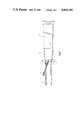
- FIG. 2 is the side elevation of the drier of FIG. 1,
- FIG. 3 is a cross section of the drier of FIG. 1, and
- FIG. 4 is a perspective view of the inlet of the drier.
- the drier is preferably a continuous tube having two sections, a combustion chamber 1 and a drying chamber consisting of two parts, a hot zone 6 and a cooler zone 10.
- the cooler zone 10 is desirably very nearly cylindrical while the hot zone 6 is desirably of a truncated conical shape.
- Feed material such as wet proteinaceous material from a rendering plant is fed into the hot zone 6 by screw a conveyor 2.
- the feedstock can be continuously fed from the outlet of the rendering plant. Since the outside surface of the conveyor 2 is exposed to the hot zone 6, it is a desirable feature of this invention to provide insulation means about the conveyor 2 to maintain the internal surfaces of the conveyor 2 at a low temperature.
- One suitable and desirable method is to provide a water jacket about the conveyor, with water being continuously circulated through the jacket. The energy values in the hot effluent water can be recovered in the rendering plant or drier if desired.
- the benefits of a jacketed screw fed conveyor are the positive drive feed, enabling supply to continue even if some of the material should inadvertently stick to the walls of the conveyor, and enabling a wider choice of materials for the construction of the conveyor and the jacket. For example stainless steel can be used.
- the screw feed outlet is designed to deliver the feedstock into the central portion of the hot zone 6. It is desirable for this purpose for the conveyor 2 to enter the dryer through the side wall of the combustion chamber 1, as illustrated in FIGS. 1 and 2.
- the feed material is adapted to fall within the hot zone 6 and move in the direction of arrow A within the drying cylinder.
- the hot zone 6 and the cooler zone 10 are, as mentioned above, desirably one continuous rotating cylinder rotated by a suitable motor (not shown), the speed of which is variable.
- the residence time of the feedstock in the hot zone 6 is for a period sufficient for fine hair and wool residues to be flashed off along with much of the surface moisture but not long enough to denature the protein material to any great extent.
- the residence time can be varied by varying the slope of the floor of the hot zone 6 and by varying the speed of rotation of the cylinder.
- the slope of the inner wall 22 in the hot zone 6 is important. If the slope is too slight, when the feedstock is being supplied at a high rate, backflow can occur towards the combustion chamber. This can lead to ignition and disastrous fires. If the slope is too steep, the benefit of the hot zone treatment can be lost. That is, inadequate flashing of hair residues and surface moisture can occur.
- the presently employed slope of the hot zone 6 is such that the angle ⁇ in FIG. 1 is about 6°.
- baffles can be provided. Such baffles need not be too prominent. For example, as shown in FIGS. 1, 2 and 3, a helical rib 23 can be provided of one or two starts.
- the slope of the inner wall in the cooler zone 10 is less than that in the hot zone 6.
- the angle of inclination of the cooler zone 10 is slight, as the residence time in this part of the chamber is designed to be preferably from 15 to 45 minutes. An angle of less than 1° is desired, and the currently employed slope is about 0.63°.
- the whole cylinder is desirably insulated as much as possible to prevent heat losses and hence conserve energy.
- the output from the cylinder feeds into a hopper 11 and thence through a discharge valve 17 to a work station where it can be packed off into suitable containers. Exhaust gases from the cylinder pass out through an outlet 12 where they can all, or part of them, be recycled with part being fed through dehumidifiers for return to the combustion chamber 1.
- a temperature sensor is provided to measure the temperature of the exhaust gases. This temperature is designed to be 110° C. ⁇ 5° C., more preferably ⁇ 2° C. If the temperature varies from this amount then a signal is generated to vary the supply of the fuel (e.g., natural gas) to the flame in the combustion chamber 1. This is designed to give a product with a moisture content of just less than 8%. If a lower moisture content is desired, then the outlet sensor will be set to detect variations from a higher temperature. For example, a sensor detecting variations from a temperature of 135° C. can yield a product with a moisture content of 11/2-2%. A temperature lower than 110° C. can be used where higher moisture contents are required.
- the fuel e.g., natural gas
- the internal surface of the rotating cylinder is provided with baffles 21, desirably positioned uniformly throughout the internal circumferance of the cylinder.
- the baffles 21 are designed to lift the feedstock continuously so that the feedstock is as much as possible falling within the cylinder. In this fashion it is exposed to the flow of heated air for the greatest time possible, which increases the drying rate.
- the baffles or flights 7 can around the inner circumference of the cylinder.
- the cylinder is driven through a variable speed motor, desirably through a suitable reduction gear box (not shown).
- the cylinder is carried on suitable bearing rollers 19 and 20 (FIG. 3) and a similar pair or pairs at necessary places along the length of the cylinder.
- the bearing rollers are adapted to rotate on a suitable spindle and bear against suitable support rings 8 (shown in FIG. 2).
- an annular flange 9 located adjacent the support rings 8 engages against a thrust roller 18.
- the rotational speed will be chosen in combination with the other parameters.
- One suitable speed is 6 RPM.
- the rotating cylinder is supported on a suitable support means such as a stand 14.
- the combustion chamber 1 is fixed and is supported by a suitable support stand such as a stand 13.
- the heating is desirably by burning a suitable flammable fuel such as natural gas within the combustion chamber 1 which is open directly into the hot zone 6. However it is desired that no live flame actually contacts the feedstock. To ensure sufficient heat is transferred into the hot zone 6 and into the cooler zone 10, air is forced through the flame in the combustion chamber 1 at sufficient speed to generate the required temperature gradient throughout the apparatus. Any recycled exhaust gases are fed into the combustion chamber 1.
Landscapes
- Engineering & Computer Science (AREA)
- Mechanical Engineering (AREA)
- General Engineering & Computer Science (AREA)
- Drying Of Solid Materials (AREA)
Applications Claiming Priority (2)
| Application Number | Priority Date | Filing Date | Title |
|---|---|---|---|
| NZ209889A NZ209889A (en) | 1984-10-16 | 1984-10-16 | Two-stage rotary drier for particulate material |
| NZ209889 | 1984-10-16 |
Publications (1)
| Publication Number | Publication Date |
|---|---|
| US4668185A true US4668185A (en) | 1987-05-26 |
Family
ID=19920940
Family Applications (1)
| Application Number | Title | Priority Date | Filing Date |
|---|---|---|---|
| US06/787,925 Expired - Fee Related US4668185A (en) | 1984-10-16 | 1985-10-16 | Process and apparatus for drying organic material in a rotary dryer |
Country Status (6)
| Country | Link |
|---|---|
| US (1) | US4668185A (fr) |
| EP (1) | EP0178920B1 (fr) |
| AT (1) | ATE77878T1 (fr) |
| AU (1) | AU585537B2 (fr) |
| DE (1) | DE3586278D1 (fr) |
| NZ (1) | NZ209889A (fr) |
Cited By (2)
| Publication number | Priority date | Publication date | Assignee | Title |
|---|---|---|---|---|
| US9689441B2 (en) | 2015-04-10 | 2017-06-27 | Gencor Industries, Inc. | Horizontal cam stop |
| US9689611B2 (en) | 2014-08-20 | 2017-06-27 | Gencor Industries, Inc. | Locking cam stop |
Families Citing this family (2)
| Publication number | Priority date | Publication date | Assignee | Title |
|---|---|---|---|---|
| DE3616218C1 (en) * | 1986-05-14 | 1987-07-02 | Rheinische Braunkohlenw Ag | Method for continuous drying of water-containing bulk materials |
| CN103486832A (zh) * | 2012-06-11 | 2014-01-01 | 四川制药制剂有限公司 | 用于对原料进行粉碎烘干的系统 |
Citations (6)
| Publication number | Priority date | Publication date | Assignee | Title |
|---|---|---|---|---|
| US3155380A (en) * | 1962-06-25 | 1964-11-03 | Lessard Gerard Arthur Armand | Multi-unit kiln for the production of lightweight aggregate |
| US3950861A (en) * | 1974-11-29 | 1976-04-20 | Stearns-Roger Corporation | Rotary dryer for stringy material |
| US4339883A (en) * | 1979-07-02 | 1982-07-20 | Waldmann Guenter | Process and apparatus for the separation of harmful substances from waste gases, particularly in the drying of wood chips |
| US4464111A (en) * | 1982-10-20 | 1984-08-07 | Measurex Corporation | System and process for controlling a calciner |
| US4504222A (en) * | 1983-09-13 | 1985-03-12 | Jude Engineering, Inc. | Screw conveyer and furnace |
| US4573278A (en) * | 1982-01-19 | 1986-03-04 | Akt Consultants Pty, Limited | Apparatus for the dehydration of organic material |
Family Cites Families (7)
| Publication number | Priority date | Publication date | Assignee | Title |
|---|---|---|---|---|
| DE108390C (fr) * | ||||
| US2715283A (en) * | 1953-03-20 | 1955-08-16 | Edw Renneburg & Sons Co | Rotary dryers |
| US2783548A (en) * | 1955-06-08 | 1957-03-05 | Edw Renneburg & Sons Co | Rotary dryers |
| US3401923A (en) * | 1966-02-17 | 1968-09-17 | Wilmot Eng Co | Dryer |
| DE1804144A1 (de) * | 1968-10-19 | 1970-04-30 | Uhde Gmbh Friedrich | Vorrichtung zum Loesen von anbackender Granulatmasse |
| DE2060040A1 (de) * | 1969-12-22 | 1971-07-01 | Stassfurt Veb Chemieanlagenbau | Beschickungsvorrichtung fuer Drehrohroefen,Trockentrommeln u.dgl.,insbesondere zum Beschicken mit plastischem,breiigem und stark haftendem Gut |
| US4177575A (en) * | 1977-09-19 | 1979-12-11 | Cannon Limited | Organic material treatment process |
-
1984
- 1984-10-16 NZ NZ209889A patent/NZ209889A/en unknown
-
1985
- 1985-10-16 DE DE8585307457T patent/DE3586278D1/de not_active Expired - Lifetime
- 1985-10-16 US US06/787,925 patent/US4668185A/en not_active Expired - Fee Related
- 1985-10-16 EP EP85307457A patent/EP0178920B1/fr not_active Expired
- 1985-10-16 AU AU48749/85A patent/AU585537B2/en not_active Ceased
- 1985-10-16 AT AT85307457T patent/ATE77878T1/de active
Patent Citations (6)
| Publication number | Priority date | Publication date | Assignee | Title |
|---|---|---|---|---|
| US3155380A (en) * | 1962-06-25 | 1964-11-03 | Lessard Gerard Arthur Armand | Multi-unit kiln for the production of lightweight aggregate |
| US3950861A (en) * | 1974-11-29 | 1976-04-20 | Stearns-Roger Corporation | Rotary dryer for stringy material |
| US4339883A (en) * | 1979-07-02 | 1982-07-20 | Waldmann Guenter | Process and apparatus for the separation of harmful substances from waste gases, particularly in the drying of wood chips |
| US4573278A (en) * | 1982-01-19 | 1986-03-04 | Akt Consultants Pty, Limited | Apparatus for the dehydration of organic material |
| US4464111A (en) * | 1982-10-20 | 1984-08-07 | Measurex Corporation | System and process for controlling a calciner |
| US4504222A (en) * | 1983-09-13 | 1985-03-12 | Jude Engineering, Inc. | Screw conveyer and furnace |
Non-Patent Citations (6)
| Title |
|---|
| "Gas Drier--A First", published in Food Processing News--Meat, Oct. 1986, p. 11. |
| Brochure entitled, "Flo-Dry Rotary Dryer", 11/1985. |
| Brochure entitled, "Marinz Continuous Low Temperature Rendering System", 8/1984. |
| Brochure entitled, Flo Dry Rotary Dryer , 11/1985. * |
| Brochure entitled, Marinz Continuous Low Temperature Rendering System , 8/1984. * |
| Gas Drier A First , published in Food Processing News Meat, Oct. 1986, p. 11. * |
Cited By (2)
| Publication number | Priority date | Publication date | Assignee | Title |
|---|---|---|---|---|
| US9689611B2 (en) | 2014-08-20 | 2017-06-27 | Gencor Industries, Inc. | Locking cam stop |
| US9689441B2 (en) | 2015-04-10 | 2017-06-27 | Gencor Industries, Inc. | Horizontal cam stop |
Also Published As
| Publication number | Publication date |
|---|---|
| AU4874985A (en) | 1986-04-24 |
| EP0178920A2 (fr) | 1986-04-23 |
| AU585537B2 (en) | 1989-06-22 |
| DE3586278D1 (de) | 1992-08-06 |
| EP0178920B1 (fr) | 1992-07-01 |
| ATE77878T1 (de) | 1992-07-15 |
| EP0178920A3 (en) | 1987-10-21 |
| NZ209889A (en) | 1988-02-12 |
Similar Documents
| Publication | Publication Date | Title |
|---|---|---|
| JP4191758B2 (ja) | 生動物素材の処理方法 | |
| JPH0451235B2 (fr) | ||
| CA2616812A1 (fr) | Ameliorations apportees a un procede de deshydratation de matieres pateuses et/ou a un appareil destine a la deshydratation de matieres pateuses | |
| US5167372A (en) | Apparatus and process for reducing size and moisture content of materials | |
| US3906961A (en) | Rotary tobacco dryer | |
| US4668185A (en) | Process and apparatus for drying organic material in a rotary dryer | |
| GB2139072A (en) | Process for the production of fodder and fat from animal raw materials | |
| CS209911B2 (en) | Method of drying the products of the plant origin and device for ececuting the same | |
| JP2001321146A (ja) | 米飯残渣の乾燥方法及び回転ドラム式乾燥機 | |
| US3593429A (en) | Method of dehydrating a crop | |
| KR20040062824A (ko) | 음식물쓰레기 무취발효소멸 건조장치 | |
| US3824065A (en) | Method of drying a product | |
| US3360868A (en) | Method of dehydrating whole grain | |
| US3738796A (en) | Apparatus and method for dehydrating wet particulate matter and for disposing of waste products therefrom | |
| JPS60900A (ja) | 泥状物の乾燥方法 | |
| JPH0242933A (ja) | 玉葱乾燥方法 | |
| WO1985002248A1 (fr) | Procede de traitement thermique de materiaux particulaires et dispositif de chauffe utilise pour mettre en oeuvre ce procede | |
| EP3421913A1 (fr) | Installation de séchage de boue, procédé de séchage de boue et utilisation d'une installation de séchage de boue | |
| RU2077210C1 (ru) | Устройство для сушки картофельного пюре | |
| JP2001221571A (ja) | 回転ドラム式乾燥機及びその運転方法 | |
| CN108844320B (zh) | 自焚式烘干机及其烘干方法 | |
| US12078416B2 (en) | Slurry drying plant, a method for drying slurry and use of a slurry drying plant | |
| KR790001907B1 (ko) | 가열 제습방법 | |
| JP2002350061A (ja) | 熱風回転乾燥機 | |
| JP3435829B2 (ja) | 厨芥処理装置 |
Legal Events
| Date | Code | Title | Description |
|---|---|---|---|
| AS | Assignment |
Owner name: PACIFIC PROTEINS LIMITED, MARK RD., MT. MAUNGANUI, Free format text: ASSIGNMENT OF ASSIGNORS INTEREST.;ASSIGNOR:TAYLOR, ANDREW W.;REEL/FRAME:004677/0127 Effective date: 19870114 |
|
| FEPP | Fee payment procedure |
Free format text: PAYOR NUMBER ASSIGNED (ORIGINAL EVENT CODE: ASPN); ENTITY STATUS OF PATENT OWNER: SMALL ENTITY |
|
| FPAY | Fee payment |
Year of fee payment: 4 |
|
| REMI | Maintenance fee reminder mailed | ||
| LAPS | Lapse for failure to pay maintenance fees | ||
| FP | Lapsed due to failure to pay maintenance fee |
Effective date: 19950531 |
|
| STCH | Information on status: patent discontinuation |
Free format text: PATENT EXPIRED DUE TO NONPAYMENT OF MAINTENANCE FEES UNDER 37 CFR 1.362 |