US4636186A - Apparatus for setting and shaping glued cigarette packs - Google Patents
Apparatus for setting and shaping glued cigarette packs Download PDFInfo
- Publication number
- US4636186A US4636186A US06/683,109 US68310984A US4636186A US 4636186 A US4636186 A US 4636186A US 68310984 A US68310984 A US 68310984A US 4636186 A US4636186 A US 4636186A
- Authority
- US
- United States
- Prior art keywords
- packs
- drying turret
- drying
- pockets
- Prior art date
- Legal status (The legal status is an assumption and is not a legal conclusion. Google has not performed a legal analysis and makes no representation as to the accuracy of the status listed.)
- Expired - Lifetime
Links
Images


Classifications
-
- B—PERFORMING OPERATIONS; TRANSPORTING
- B65—CONVEYING; PACKING; STORING; HANDLING THIN OR FILAMENTARY MATERIAL
- B65B—MACHINES, APPARATUS OR DEVICES FOR, OR METHODS OF, PACKAGING ARTICLES OR MATERIALS; UNPACKING
- B65B61/00—Auxiliary devices, not otherwise provided for, for operating on sheets, blanks, webs, binding material, containers or packages
- B65B61/002—Auxiliary devices, not otherwise provided for, for operating on sheets, blanks, webs, binding material, containers or packages for drying glued or sealed packages
Definitions
- the invention relates to an apparatus for producing packs with folding tabs joined by means of glueing, especially cigarette packs made of (thin) cardboard, which packs are supplied to a drying turret immediately after completion.
- the invention is primarily concerned with problems arising in the production of cuboid cigarette packs, in particular so-called hinge-lid packs.
- side tabs forming narrow side faces are joined to one another by means of glueing. So that the adhesive has the opportunity of setting, without the folding tabs glued to one another being able to shift relative to one another during this time, the finished packs are received temporarily in a drying turret.
- An advantageous embodiment of this is described in U.S. Pat. No. 4,179,864.
- This known drying turret forming part of the packaging machine is provided, along its periphery, with a plurality of radially directed pockets each of which serves to receive a pack.
- the pockets of the drying turret are designed so that the exact cuboid format of the packs is maintained or stabilized.
- the glue bond between the folding tabs has hardened substantially, and furthermore the shape of the packs is fixed precisely.
- the object on which the invention is based is to develop further and improve a packaging machine of the type described in the introduction, in such a way that it is possible to stabilize folding tabs joined to one another by means of glueing, whilst at the same time ensuring a high output of the packaging machine, and even in the case of packs where glueing is critical.
- the apparatus according to the invention is defined in that the (first) drying turret is followed by at least one further (second) drying turret for receiving the packs temporarily.
- the first drying turret known per se causes initial setting or hardening of the adhesive, whilst at the same time maintaining and fixing the external shape of the pack precisely, especially the cuboid shape.
- the following further drying turret preferably has a simpler design in the form of pockets for receiving the packs.
- the packs are also retained in this second drying turret, so that packs having glue bonds of high strength or stability leave the drying turret and can then be supplied to further packaging steps without delay.
- the second following drying turret is provided, along its periphery, with pockets, in each of which a plurality of packs located next to one another in the axial direction (pack group) is received.
- the packs coming from the first drying turret travel via a feed conveyor to the second drying turret and directly into a pocket provided in a feed station. Because of their shape, the pockets allow the packs or pack group to move in the axial direction through the pocket, entering on one side of the turret and leaving on the other side in the region of adjacent feed and push-out stations.
- the cigarette groups each to be received by a pocket, are formed as a result of the accumulation of continuously supplied packs within a pocket, and the following packs are temporarily prevented from being transported further by being clamped.
- the pack group as a whole is ejected from the pocket and moved up to a discharge conveyor by means of a slide.
- the apparatus formed is efficient in terms of the number of packs produced and guarantees packs of perfect quality.
- FIG. 1 shows the relevant part of the packaging machine in a diagrammatic side view
- FIG. 2 shows a horizontal projection of FIG. 1
- FIG. 3 shows a view of the apparatus offset 90° relative to FIG. 1, with a plan view of a second drying turret,
- FIG. 4 shows a side view of the drying turret as a detail, on an enlarged scale
- FIG. 5 shows a view of the (second) drying turret, offset 90° relative to FIG. 4, together with the feed and discharge members,
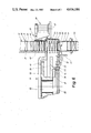
- FIG. 6 shows a detail of the (second) drying turret in the region where the packs are pushed in, in a horizontal section and on an enlarged scale
- FIG. 7 shows a horizontal or radial section through the drying turret, offset in the peripheral direction relative to FIG. 6.
- the exemplary embodiment illustrated in the drawings relates to a packaging machine or parts of it for producing cuboid cigarette packs 10. These are preferably hinge-lid packs made of thin cardboard.
- the part of the packaging machine relating to the production of the actual pack 10 is not shown in detail, but preferably corresponds to the embodiment according to German Offenlegungsschrift No. 2,440,006 U.S. Pat. Nos. 4,084,393 and 4,308,708.
- the cigarette packs 10 are formed so that side tabs overlapping one another in the region of narrow side faces 11 are joined together by means of adhesive.
- the cigarette packs 10, together with adhesive which has not yet hardened, are conveyed on a pack track 12, supplied to a transfer turret 13 by being lifted, and transferred from the latter to a first drying turret 14.
- This is preferably designed in the way described in U.S. Pat. No. 4,179,864, in particular with a plurality of radially directed pockets 15, each intended for receiving a cigarette pack 10.
- the pockets 15 are designed so that a forming pressure is exerted on the cigarette packs 10, and their cuboid shape is thereby corrected and stabilized.
- the packs are appropriately heated slightly in this first folding turret 14.
- the packs are pushed out of the pockets 15 by an ejector 16 (FIG. 2) and introduced into a belt conveyor which directly adjoins the drying turret 14 and which is at the same time a feed conveyor 17 for a further (second) drying turret 18.
- the feed conveyor 17 (FIGS. 1, 2 and 5) consists of a revolving endless upper side 19 and a likewise endlessly revolving lower side 20.
- the cigarette packs 10 are received between these conveyor sides in a relative position in which the elongate side faces 11 are directed downwards and upwards, that is to say end faces 21 point to the sides.
- each pack group 23 assigned to a pocket 22 consists of four cigarette packs 10.
- the drying turret 18 is arranged in a plane offset 90° relative to the first drying turret 14, both being in vertical planes.
- the pockets 22 of the second drying turret 18 are designed as axially continuous chambers or orifices, through which the pack group 23 is pushed in the axial direction.
- Each pocket consists of two side walls 24 and 25 (FIG. 4), of which one (the side wall 25) is moveable in the present case.
- This one wall is part of a two-armed wall lever 26 which is pivoted about a pivot bearing 27 and the free supporting arm of which is supported on a fixed cam disk 29 by means of a tracer roller 28.
- a (tension) spring 30 engaging on the free arm of the wall lever 26 ensures that the side wall 25 is loaded in the closing position.
- the side walls 25 are each opened counter to the tension of the spring 30 because the tracer roller 28 runs onto an elevation of the cam disk 29.
- the radially outer side of the pockets 22 is bounded by a fixed annular wall 33.
- a closed supporting disk 34 which rotates in synchronism and to which the fixed side walls 24 and the pivotable side walls 25 are also attached, forms the boundary of the pockets 22 on the opposite an inner side.
- the packs 10 are secured between the side walls 24 and 25 by being clamped.
- a pocket stop 35 (FIGS. 4-7) on the opposite or exit side.
- this is designed as a two-armed lever with a stop projection 36 which projects into the pocket 22 from the exit side.
- a pivot bearing 37 is attached to a fixed retaining disk 38.
- One leg 39 of the pocket stop 35, this leg resting on the stop projection 36, is supported on a pot-shaped cam disk 41 by means of a track roller 40.
- a (tension) spring 42 engaging on the pocket stop 35 ensures that the track roller 40 constantly rests against the cam disk 41, and consequently the stop projection 36 is loaded in the direction of retraction.
- the stop projection 36 When the pack group 23 is conveyed into the pocket 22, the stop projection 36 is in the position moved into the pocket 22 (the unbroken line in FIG. 6). The pack group 23 runs against the stop projection 36. When the drying turret 18 moves further, the stop projection 36 is retracted (the position shown by a broken line). The cigarette packs 10 can now be moved in the pocket 22 free of any load on them.
- a bevelled run-in edge 43 in a turret side-wall 44 causes the pack group 23 to be aligned in the pocket 22 as a result of slight displacement towards the opposite side (turret side-wall 45).
- the pockets 22 are designed so that the cigarette packs 10 supplied at the height of a horizontal center plane are received in the pockets 22 with their end faces 21 directed radially outwards and inwards.
- the side faces 11 point in the peripheral direction.
- the following cigarette packs are stopped momentarily in the region of the feed conveyor 17.
- the (accumulated) cigarette packs 10 located at the front in the direction of movement are stopped by being clamped.
- a clamping plate 46 (FIG. 6) is mounted, so as to be moveable, laterally next to the feed conveyor 17.
- This clamping plate is attached to an elongate lever arm 47 which is driven with a pulsating action by means of a suitable gear 48.
- several cigarette packs are pressed by means of their end faces 21 against a fixed lateral guide 49 next to the feed conveyor 17.
- the clamping plate 46 is moved back, so that the accumulated cigarette packs 10 can be conveyed into the pocket 22.
- the lateral guide 49 is connected to the turret side-wall 44.
- the drying turret 18 is driven in an counter-clockwise direction.
- the cigarette packs are located in the pockets 22 of the drying turret 18 during a virtually complete revolution of the latter.
- the push-out station 32 is formed directly underneath the feed station 31.
- the pack group 23 is conveyed out of the particular pocket 22 by an ejector 50 and via a helical intermediate piece 51 right into a discharge conveyor 52.
- the latter consists likewise of upper and lower sides, between which are received the packs having hardened glue bonds.
- the intermediate piece 51 consists of oblique or arcuate guide walls as a transition from the pocket 22 to the discharge conveyor 52 extending in a horizontal plane.
- the ejector 50 is designed as an angled arm with a horizontal leg 55 which, during the to-and-fro movement of the ejector 50, is moved through the pocket 22 to be emptied up to the discharge conveyor 52.
- the remaining part of the ejector 50 is mounted, so as to be displaceable, laterally next to the drying turret 18, specifically on essentially horizontal supporting rods 54 directed axis-parallel relative to the drying turret 18.
- the ejector 50 designed in this way is driven by means of a crank 55 with a revolving driving pulley 56 and a connecting rod 57.
- the latter is connected (pivotably) to a slide 58 carrying the ejector 50. This slide is mounted so as to slide on the supporting rods 54.
- the outer annular wall 33 and the turret side-walls 44 and 45 of the drying turret 18 are interrupted or provided with recesses 59 and 60 in the region of the push-out station 32 and in the region of the feed station 31.
- the recess 59 in the region of the push-out station 32 allows the free passage of the ejector 50 or the leg 53.
- the further design of the drying turret 18 in the present embodiment emerges, above all, from FIGS. 6 and 7.
- the turret side-walls 44 and 45 form together with the annular wall 33 a closed housing.
- the drive for the drying turret 18 is also accommodated in this.
- a main wheel 62 mounted on a fixed central axle 63 is driven via a toothed-wheel gear 61.
- the supporting disk 34 to the outer periphery of which the pockets 22 are attached, revolves together with the main wheel 62 and is therefore connected to it.
- the cam disk 41 is also arranged on the supporting disk 34 as a laterally projecting rim.
- the cam disk 29 assigned to the pockets 22 or to the moveable side wall 25 of these is connected to the axle 63.
- the cam disk 29 is identical to the retaining disk 38, the outer periphery of this retaining disk 38 at the same time forming the cam disk 29.
- the retaining disk is provided with an orifice 64, through which passes the leg 39 of the pocket stop 35, together with the track roller 40, so as to come up against the cam disk 41.
- the capacities of the drying turrets 14 and 18 are such that each pack is received for approximately 15 seconds in each drying turret.
- the total drying time of 30 seconds is sufficient to obtain stable packs.
- the second drying turret 18 can be heated in a suitable way.
Abstract
Description
Claims (13)
Applications Claiming Priority (2)
| Application Number | Priority Date | Filing Date | Title |
|---|---|---|---|
| DE19843400650 DE3400650A1 (en) | 1984-01-11 | 1984-01-11 | PACKING MACHINE FOR PACKINGS WITH FOLDING FLAPS CONNECTED BY ADHESIVE |
| DE3400650 | 1984-01-11 |
Publications (1)
| Publication Number | Publication Date |
|---|---|
| US4636186A true US4636186A (en) | 1987-01-13 |
Family
ID=6224635
Family Applications (1)
| Application Number | Title | Priority Date | Filing Date |
|---|---|---|---|
| US06/683,109 Expired - Lifetime US4636186A (en) | 1984-01-11 | 1984-12-18 | Apparatus for setting and shaping glued cigarette packs |
Country Status (6)
| Country | Link |
|---|---|
| US (1) | US4636186A (en) |
| EP (2) | EP0149822B1 (en) |
| JP (1) | JPH0678085B2 (en) |
| BR (1) | BR8500107A (en) |
| CA (1) | CA1251181A (en) |
| DE (3) | DE3400650A1 (en) |
Cited By (14)
| Publication number | Priority date | Publication date | Assignee | Title |
|---|---|---|---|---|
| US4942715A (en) * | 1987-10-28 | 1990-07-24 | Focke & Co. (Gmbh & Co.) | Apparatus for the stabilization and drying of cuboid packs |
| US4979349A (en) * | 1988-05-05 | 1990-12-25 | Focke & Co. (Gmbh & Co.) | Packaging machine for flip-top boxes |
| GB2242666A (en) * | 1990-04-04 | 1991-10-09 | Gd Spa | Apparatus for the temporary storage of products |
| US5129209A (en) * | 1990-01-12 | 1992-07-14 | Focke & Co. | Apparatus for stabilizing the shape of cuboidal (cigarette) packs |
| US5154687A (en) * | 1991-09-30 | 1992-10-13 | Gate Pallet Systems, Inc. | Rotary accumulator for pallet stringers or decking members |
| US5210992A (en) * | 1990-11-27 | 1993-05-18 | Focke & Co. | Apparatus for shaping and for setting the glue of cuboidal (cigarette) packs |
| US5901530A (en) * | 1996-11-18 | 1999-05-11 | G.D S.P.A. | Wrapping method for rigid cigarette packets |
| US6115991A (en) * | 1998-01-27 | 2000-09-12 | G. D Societa Per Azioni | Machine for conditioning packets of cigarettes |
| EP1122171A1 (en) | 2000-01-31 | 2001-08-08 | Focke & Co. (GmbH & Co.) | Method and device for applying a code to (cigarette)-packages |
| US20030033787A1 (en) * | 2001-07-13 | 2003-02-20 | Azionaria Costruzioni Macchine Automatiche A.C.M.A. S.P.A. | Method and unit for wrapping sweets |
| CN100393251C (en) * | 2004-11-05 | 2008-06-11 | 济南兰剑物流科技有限责任公司 | Cigarette sorting machine |
| WO2008071265A1 (en) * | 2006-12-13 | 2008-06-19 | Focke & Co. (Gmbh & Co. Kg) | Drying turret for cigarette packs |
| CN105000227A (en) * | 2015-06-19 | 2015-10-28 | 湖北中烟工业有限责任公司 | Drying wheel of cigarette hard packet packer |
| US10759549B2 (en) | 2015-08-31 | 2020-09-01 | Sig Technology Ag | Device and method for the drying of packaging |
Families Citing this family (10)
| Publication number | Priority date | Publication date | Assignee | Title |
|---|---|---|---|---|
| DE3605177A1 (en) * | 1986-02-19 | 1987-08-20 | Focke & Co | DEVICE FOR STORING (CIGARETTE) PACKS |
| DE3638627A1 (en) * | 1986-11-12 | 1988-05-26 | Focke & Co | METHOD AND DEVICE FOR SEALING FOLDING FLAPS OF A PACK |
| DE3701768A1 (en) * | 1987-01-22 | 1988-08-04 | Focke & Co | PACKING MACHINE WITH DRYING REVOLVER |
| DE3929980A1 (en) * | 1989-09-08 | 1991-03-21 | Schmermund Maschf Alfred | DEVICE FOR PROMOTING SQUARE OBJECTS |
| CN1079765C (en) * | 1995-03-23 | 2002-02-27 | 吉第联合股份公司 | Method and apparatus for packing product |
| IT1306254B1 (en) * | 1995-05-05 | 2001-06-04 | Gd Spa | METHOD AND MACHINE FOR PACKAGING PRODUCTS |
| DE102005059620A1 (en) * | 2005-12-12 | 2007-06-14 | Focke & Co.(Gmbh & Co. Kg) | Device for producing packages with shrink film |
| DE102008010433A1 (en) * | 2008-02-21 | 2009-08-27 | Focke & Co.(Gmbh & Co. Kg) | Method and device for producing packages for folding box type cigarettes |
| DE102008029929A1 (en) * | 2008-06-26 | 2009-12-31 | Focke & Co.(Gmbh & Co. Kg) | Method and device for producing packages |
| DE102014012968A1 (en) * | 2014-09-08 | 2016-03-10 | Focke & Co. (Gmbh & Co. Kg) | Method and device for shape stabilization of packages |
Citations (17)
| Publication number | Priority date | Publication date | Assignee | Title |
|---|---|---|---|---|
| US90711A (en) * | 1869-06-01 | Improved machine for manufacturing webbing foh ladies fans | ||
| US1876931A (en) * | 1928-03-28 | 1932-09-13 | Us Envelope Co | Machine for making paper cups |
| US1934540A (en) * | 1931-03-24 | 1933-11-07 | Us Envelope Co | Apparatus for drying paper cups |
| US2512922A (en) * | 1946-11-04 | 1950-06-27 | Molins Machine Co Ltd | Packet making or other machines comprising intermittently rotatable disks or turrets |
| US2591135A (en) * | 1945-06-18 | 1952-04-01 | Molins Machine Co Ltd | Packet making machine |
| US3385176A (en) * | 1966-05-31 | 1968-05-28 | Reynolds Metals Co | Method and apparatus for making a cigarette package construction or the like |
| US3899863A (en) * | 1973-03-05 | 1975-08-19 | Gd Spa | Apparatus for the exiting of products, particularly packets of cigarettes and similar, from a wrapping packing line for the said products |
| US4084393A (en) * | 1974-08-21 | 1978-04-18 | Focke & Pfuhl | Apparatus for making and filling hinged boxes of a foldable material |
| US4100718A (en) * | 1976-03-29 | 1978-07-18 | Focke & Pfuhl | Means for the production and filling of a parallelepipedic packet |
| US4170073A (en) * | 1977-12-01 | 1979-10-09 | Kay-Ray, Inc. | Wide dynamic range multi-zone drying method and apparatus for controlling product moisture |
| US4179864A (en) * | 1976-07-22 | 1979-12-25 | Focke & Pfuhl | Apparatus for setting and shaping glued cigarette packs |
| CA1071001A (en) * | 1978-03-23 | 1980-02-05 | Heinz Focke | Process and apparatus for shaping or improving the shape of oblong packs |
| US4265073A (en) * | 1978-09-14 | 1981-05-05 | G.D. S.P.A. | Apparatus for forming and overwrapping batches of products |
| US4308667A (en) * | 1977-04-12 | 1982-01-05 | Babcock-Bsh Aktiengesellschaft | Continuously operating multistage drying installation and a process for continuously drying a workpiece |
| US4330976A (en) * | 1978-07-11 | 1982-05-25 | Molins Limited | Packing machines |
| US4484432A (en) * | 1980-12-06 | 1984-11-27 | Maschinenfabrik Alfred Schmermund Gmbh & Co. | Bottom-folding packaging machine |
| US4559758A (en) * | 1983-02-08 | 1985-12-24 | G.D Societa' Per Azioni | Cigarette packing machine |
Family Cites Families (8)
| Publication number | Priority date | Publication date | Assignee | Title |
|---|---|---|---|---|
| DE1030669B (en) * | 1954-09-27 | 1958-05-22 | Bahlsen Werner | Device for the continuous production of collapsible containers |
| CH418959A (en) * | 1964-04-21 | 1966-08-15 | Carl Drohmann Ges Mit Beschrae | Device for dividing and feeding groups of items delivered in rows to a multipacking machine |
| DE1270476B (en) * | 1964-08-19 | 1968-06-12 | Holstein & Kappert Maschf | Device for welding the tips of the pack |
| DE1586087A1 (en) * | 1967-04-19 | 1970-03-26 | Hauni Werke Koerber & Co Kg | Magazine for storing packets of cigarettes |
| DE1561532A1 (en) * | 1967-11-24 | 1970-04-16 | Hoerauf Michael Maschf | Method and device for the production of workpieces preferably designed as sleeves for packaging |
| GB1559796A (en) * | 1975-09-13 | 1980-01-30 | Molins Ltd | Apparatus for handling packets |
| DE2632968C2 (en) * | 1976-07-22 | 1985-04-18 | Focke & Pfuhl, 2810 Verden | Device for shaping or improving the shape of cuboid packs |
| IT1158537B (en) * | 1982-12-28 | 1987-02-18 | Sasib Spa | AUTOMATIC CIGARETTE PACKING MACHINE IN RIGID PACKAGES IN PARTICULAR IN PACKAGES OF THE TYPE WITH HINGE LID |
-
1984
- 1984-01-11 DE DE19843400650 patent/DE3400650A1/en not_active Withdrawn
- 1984-12-18 US US06/683,109 patent/US4636186A/en not_active Expired - Lifetime
- 1984-12-19 DE DE8787105276T patent/DE3485674D1/en not_active Expired - Lifetime
- 1984-12-19 DE DE8484115818T patent/DE3471061D1/en not_active Expired
- 1984-12-19 EP EP84115818A patent/EP0149822B1/en not_active Expired
- 1984-12-19 EP EP87105276A patent/EP0243757B1/en not_active Expired - Lifetime
- 1984-12-21 CA CA000470852A patent/CA1251181A/en not_active Expired
- 1984-12-28 JP JP59275008A patent/JPH0678085B2/en not_active Expired - Fee Related
-
1985
- 1985-01-10 BR BR8500107A patent/BR8500107A/en not_active IP Right Cessation
Patent Citations (18)
| Publication number | Priority date | Publication date | Assignee | Title |
|---|---|---|---|---|
| US90711A (en) * | 1869-06-01 | Improved machine for manufacturing webbing foh ladies fans | ||
| US1876931A (en) * | 1928-03-28 | 1932-09-13 | Us Envelope Co | Machine for making paper cups |
| US1934540A (en) * | 1931-03-24 | 1933-11-07 | Us Envelope Co | Apparatus for drying paper cups |
| US2591135A (en) * | 1945-06-18 | 1952-04-01 | Molins Machine Co Ltd | Packet making machine |
| US2512922A (en) * | 1946-11-04 | 1950-06-27 | Molins Machine Co Ltd | Packet making or other machines comprising intermittently rotatable disks or turrets |
| US3385176A (en) * | 1966-05-31 | 1968-05-28 | Reynolds Metals Co | Method and apparatus for making a cigarette package construction or the like |
| US3899863A (en) * | 1973-03-05 | 1975-08-19 | Gd Spa | Apparatus for the exiting of products, particularly packets of cigarettes and similar, from a wrapping packing line for the said products |
| US4308708A (en) * | 1974-08-21 | 1982-01-05 | Focke & Pfuhl | Apparatus for folding hinged lid boxes from cardboard blanks and filling them with tinfoil wrapped cigarette blocks |
| US4084393A (en) * | 1974-08-21 | 1978-04-18 | Focke & Pfuhl | Apparatus for making and filling hinged boxes of a foldable material |
| US4100718A (en) * | 1976-03-29 | 1978-07-18 | Focke & Pfuhl | Means for the production and filling of a parallelepipedic packet |
| US4179864A (en) * | 1976-07-22 | 1979-12-25 | Focke & Pfuhl | Apparatus for setting and shaping glued cigarette packs |
| US4308667A (en) * | 1977-04-12 | 1982-01-05 | Babcock-Bsh Aktiengesellschaft | Continuously operating multistage drying installation and a process for continuously drying a workpiece |
| US4170073A (en) * | 1977-12-01 | 1979-10-09 | Kay-Ray, Inc. | Wide dynamic range multi-zone drying method and apparatus for controlling product moisture |
| CA1071001A (en) * | 1978-03-23 | 1980-02-05 | Heinz Focke | Process and apparatus for shaping or improving the shape of oblong packs |
| US4330976A (en) * | 1978-07-11 | 1982-05-25 | Molins Limited | Packing machines |
| US4265073A (en) * | 1978-09-14 | 1981-05-05 | G.D. S.P.A. | Apparatus for forming and overwrapping batches of products |
| US4484432A (en) * | 1980-12-06 | 1984-11-27 | Maschinenfabrik Alfred Schmermund Gmbh & Co. | Bottom-folding packaging machine |
| US4559758A (en) * | 1983-02-08 | 1985-12-24 | G.D Societa' Per Azioni | Cigarette packing machine |
Cited By (18)
| Publication number | Priority date | Publication date | Assignee | Title |
|---|---|---|---|---|
| US4942715A (en) * | 1987-10-28 | 1990-07-24 | Focke & Co. (Gmbh & Co.) | Apparatus for the stabilization and drying of cuboid packs |
| US4979349A (en) * | 1988-05-05 | 1990-12-25 | Focke & Co. (Gmbh & Co.) | Packaging machine for flip-top boxes |
| US5129209A (en) * | 1990-01-12 | 1992-07-14 | Focke & Co. | Apparatus for stabilizing the shape of cuboidal (cigarette) packs |
| GB2242666A (en) * | 1990-04-04 | 1991-10-09 | Gd Spa | Apparatus for the temporary storage of products |
| GB2242666B (en) * | 1990-04-04 | 1993-12-15 | Gd Spa | Apparatus for the temporary storage of products while adhesive dries |
| US5210992A (en) * | 1990-11-27 | 1993-05-18 | Focke & Co. | Apparatus for shaping and for setting the glue of cuboidal (cigarette) packs |
| US5154687A (en) * | 1991-09-30 | 1992-10-13 | Gate Pallet Systems, Inc. | Rotary accumulator for pallet stringers or decking members |
| US5901530A (en) * | 1996-11-18 | 1999-05-11 | G.D S.P.A. | Wrapping method for rigid cigarette packets |
| US6115991A (en) * | 1998-01-27 | 2000-09-12 | G. D Societa Per Azioni | Machine for conditioning packets of cigarettes |
| EP1122171A1 (en) | 2000-01-31 | 2001-08-08 | Focke & Co. (GmbH & Co.) | Method and device for applying a code to (cigarette)-packages |
| US6614023B2 (en) | 2000-01-31 | 2003-09-02 | Focke & Co. (Gmbh & Co.) | Process and apparatus for providing codings on (cigarette) packs |
| EP1122171B2 (en) † | 2000-01-31 | 2009-09-23 | Focke & Co. (GmbH & Co. KG) | Method and device for applying a code to (cigarette)-packages |
| US20030033787A1 (en) * | 2001-07-13 | 2003-02-20 | Azionaria Costruzioni Macchine Automatiche A.C.M.A. S.P.A. | Method and unit for wrapping sweets |
| US6655113B2 (en) * | 2001-07-13 | 2003-12-02 | Azionaria Costruzioni Macchine Automatiche A.C.M.A. S.P.A. | Method and unit for wrapping sweets |
| CN100393251C (en) * | 2004-11-05 | 2008-06-11 | 济南兰剑物流科技有限责任公司 | Cigarette sorting machine |
| WO2008071265A1 (en) * | 2006-12-13 | 2008-06-19 | Focke & Co. (Gmbh & Co. Kg) | Drying turret for cigarette packs |
| CN105000227A (en) * | 2015-06-19 | 2015-10-28 | 湖北中烟工业有限责任公司 | Drying wheel of cigarette hard packet packer |
| US10759549B2 (en) | 2015-08-31 | 2020-09-01 | Sig Technology Ag | Device and method for the drying of packaging |
Also Published As
| Publication number | Publication date |
|---|---|
| EP0243757A2 (en) | 1987-11-04 |
| DE3400650A1 (en) | 1985-07-18 |
| EP0149822A3 (en) | 1986-02-05 |
| EP0149822A2 (en) | 1985-07-31 |
| EP0243757B1 (en) | 1992-04-22 |
| CA1251181A (en) | 1989-03-14 |
| DE3485674D1 (en) | 1992-05-27 |
| EP0243757A3 (en) | 1988-10-05 |
| BR8500107A (en) | 1985-08-20 |
| DE3471061D1 (en) | 1988-06-16 |
| JPH0678085B2 (en) | 1994-10-05 |
| JPS60158015A (en) | 1985-08-19 |
| EP0149822B1 (en) | 1988-05-11 |
Similar Documents
| Publication | Publication Date | Title |
|---|---|---|
| US4636186A (en) | Apparatus for setting and shaping glued cigarette packs | |
| US4718216A (en) | Process and apparatus for packaging cigarettes in particular | |
| US4918908A (en) | Apparatus for feeding blanks to a folding turret of a packaging machine | |
| US4840007A (en) | Packaging machine with a drying turret | |
| US4208854A (en) | Device for folding blanks of sheet material in machines for packaging articles, particularly cigarettes, into hinged-lid packets | |
| US5544467A (en) | Apparatus for producing cigarette packs | |
| US4947617A (en) | Apparatus for the production of hinge-lid packs for cigarettes | |
| US4084393A (en) | Apparatus for making and filling hinged boxes of a foldable material | |
| US4079575A (en) | Packing cigarettes | |
| US20110152050A1 (en) | Method and Device for the Production of Packages | |
| US7134257B2 (en) | Method and device for producing hard packs for cigarettes | |
| JPH0620891B2 (en) | Pack manufacturing equipment | |
| US4570421A (en) | Process and apparatus for closing cartons | |
| US4909020A (en) | Process and apparatus for wrapping, especially cigarette packs | |
| EP0741081B1 (en) | Method and machine for packing products and subsequent drying of the packages | |
| JPH02296614A (en) | Continuous packer | |
| US4646508A (en) | Apparatus for producing packs especially cigarette sticks | |
| US4476665A (en) | Packaging machine | |
| US4023513A (en) | Method and apparatus for transferring cans | |
| US5146728A (en) | Apparatus for the packaging of cigarettes | |
| US4819343A (en) | Apparatus for the storage of (cigarette) packs | |
| US1125331A (en) | Machine for making and charging paper boxes. | |
| Iles et al. | Design of a High-Speed Nonelectric Detonator Loading, Assembly, Inspection, and Packaging System | |
| ITGE930113A1 (en) | "DRYING DEVICE FOR RIGID PACKAGES, IN PARTICULAR IN CIGARETTE PACKING MACHINES" | |
| NL8602426A (en) | DEVICE FOR THE CONTINUOUS PACKING OF A PRODUCT. |
Legal Events
| Date | Code | Title | Description |
|---|---|---|---|
| AS | Assignment |
Owner name: FOCKE & CO. (GMBH & CO.), SIEMENSSTR. 1O, D - 2810 Free format text: ASSIGNMENT OF ASSIGNORS INTEREST.;ASSIGNORS:FOCKE, HEINZ;SCHONBERGER, HANS;REEL/FRAME:004607/0066 Effective date: 19841211 Owner name: FOCKE & CO. (GMBH & CO.), SIEMENSSTR. 1O, D - 2810 Free format text: ASSIGNMENT OF ASSIGNORS INTEREST;ASSIGNORS:FOCKE, HEINZ;SCHONBERGER, HANS;REEL/FRAME:004607/0066 Effective date: 19841211 |
|
| STCF | Information on status: patent grant |
Free format text: PATENTED CASE |
|
| FEPP | Fee payment procedure |
Free format text: PAYOR NUMBER ASSIGNED (ORIGINAL EVENT CODE: ASPN); ENTITY STATUS OF PATENT OWNER: LARGE ENTITY |
|
| FPAY | Fee payment |
Year of fee payment: 4 |
|
| FPAY | Fee payment |
Year of fee payment: 8 |
|
| FPAY | Fee payment |
Year of fee payment: 12 |