US4575389A - Device for bending glass plates - Google Patents
Device for bending glass plates Download PDFInfo
- Publication number
- US4575389A US4575389A US06/669,795 US66979584A US4575389A US 4575389 A US4575389 A US 4575389A US 66979584 A US66979584 A US 66979584A US 4575389 A US4575389 A US 4575389A
- Authority
- US
- United States
- Prior art keywords
- shaping
- shaping bed
- frame
- bed
- glass plates
- Prior art date
- Legal status (The legal status is an assumption and is not a legal conclusion. Google has not performed a legal analysis and makes no representation as to the accuracy of the status listed.)
- Expired - Fee Related
Links
- 239000011521 glass Substances 0.000 title claims abstract description 60
- 238000005452 bending Methods 0.000 title claims abstract description 39
- 238000007493 shaping process Methods 0.000 claims abstract description 91
- 238000011144 upstream manufacturing Methods 0.000 claims abstract description 12
- XLYOFNOQVPJJNP-UHFFFAOYSA-N water Substances O XLYOFNOQVPJJNP-UHFFFAOYSA-N 0.000 claims description 4
- 238000004064 recycling Methods 0.000 claims 3
- 230000000694 effects Effects 0.000 abstract description 3
- 230000003287 optical effect Effects 0.000 abstract description 3
- 238000010438 heat treatment Methods 0.000 description 12
- 238000009434 installation Methods 0.000 description 8
- 238000005496 tempering Methods 0.000 description 8
- 230000007246 mechanism Effects 0.000 description 5
- 230000009471 action Effects 0.000 description 3
- 238000001816 cooling Methods 0.000 description 3
- 230000000750 progressive effect Effects 0.000 description 3
- 238000007664 blowing Methods 0.000 description 2
- 230000004048 modification Effects 0.000 description 2
- 238000012986 modification Methods 0.000 description 2
- 230000008859 change Effects 0.000 description 1
- 238000010586 diagram Methods 0.000 description 1
- 230000003068 static effect Effects 0.000 description 1
Images


Classifications
-
- C—CHEMISTRY; METALLURGY
- C03—GLASS; MINERAL OR SLAG WOOL
- C03B—MANUFACTURE, SHAPING, OR SUPPLEMENTARY PROCESSES
- C03B23/00—Re-forming shaped glass
- C03B23/02—Re-forming glass sheets
- C03B23/023—Re-forming glass sheets by bending
- C03B23/025—Re-forming glass sheets by bending by gravity
- C03B23/027—Re-forming glass sheets by bending by gravity with moulds having at least two upward pivotable mould sections
-
- C—CHEMISTRY; METALLURGY
- C03—GLASS; MINERAL OR SLAG WOOL
- C03B—MANUFACTURE, SHAPING, OR SUPPLEMENTARY PROCESSES
- C03B23/00—Re-forming shaped glass
- C03B23/02—Re-forming glass sheets
- C03B23/023—Re-forming glass sheets by bending
- C03B23/025—Re-forming glass sheets by bending by gravity
- C03B23/0252—Re-forming glass sheets by bending by gravity by gravity only, e.g. sagging
- C03B23/0254—Re-forming glass sheets by bending by gravity by gravity only, e.g. sagging in a continuous way, e.g. gravity roll bending
-
- C—CHEMISTRY; METALLURGY
- C03—GLASS; MINERAL OR SLAG WOOL
- C03B—MANUFACTURE, SHAPING, OR SUPPLEMENTARY PROCESSES
- C03B35/00—Transporting of glass products during their manufacture, e.g. hot glass lenses, prisms
- C03B35/14—Transporting hot glass sheets or ribbons, e.g. by heat-resistant conveyor belts or bands
- C03B35/16—Transporting hot glass sheets or ribbons, e.g. by heat-resistant conveyor belts or bands by roller conveyors
- C03B35/161—Transporting hot glass sheets or ribbons, e.g. by heat-resistant conveyor belts or bands by roller conveyors specially adapted for bent sheets or ribbons
-
- C—CHEMISTRY; METALLURGY
- C03—GLASS; MINERAL OR SLAG WOOL
- C03B—MANUFACTURE, SHAPING, OR SUPPLEMENTARY PROCESSES
- C03B35/00—Transporting of glass products during their manufacture, e.g. hot glass lenses, prisms
- C03B35/14—Transporting hot glass sheets or ribbons, e.g. by heat-resistant conveyor belts or bands
- C03B35/16—Transporting hot glass sheets or ribbons, e.g. by heat-resistant conveyor belts or bands by roller conveyors
- C03B35/163—Drive means, clutches, gearing or drive speed control means
-
- C—CHEMISTRY; METALLURGY
- C03—GLASS; MINERAL OR SLAG WOOL
- C03B—MANUFACTURE, SHAPING, OR SUPPLEMENTARY PROCESSES
- C03B35/00—Transporting of glass products during their manufacture, e.g. hot glass lenses, prisms
- C03B35/14—Transporting hot glass sheets or ribbons, e.g. by heat-resistant conveyor belts or bands
- C03B35/16—Transporting hot glass sheets or ribbons, e.g. by heat-resistant conveyor belts or bands by roller conveyors
- C03B35/18—Construction of the conveyor rollers ; Materials, coatings or coverings thereof
- C03B35/185—Construction of the conveyor rollers ; Materials, coatings or coverings thereof having a discontinuous surface for contacting the sheets or ribbons other than cloth or fabric, e.g. having protrusions or depressions, spirally wound cable, projecting discs or tires
Definitions
- This invention relates to bending of glass plates moving in a horizontal or approximately horizontal position, under the effect of their own weight, with a device including a shaping bed made of rotating shaping elements whose surfaces in contact with the glass plates, as they advance, define increasingly curved generatrices, these shaping elements being mounted on a frame that is adjustable in height and can be inclined in the lengthwise direction of movement of the plates, by pivoting around a transverse horizontal axis located at the upstream end of the shaping bed.
- the rotating shaping elements of the shaping bed can have various configurations.
- the rotating shaping elements also participate in the conveying and are formed by flexible tubular sheaths rotatably driven around rigid curved rods. Adjustment of the radius of curvature of the bending shape, and the progression of its curvature in the direction of conveying the glass plates is achieved by the fact that the various curved rods are mounted so as to be able to be pivoted around an axis that passes through their ends, and so they can be adjusted to inclinations that are different from one another, which increasingly removes them from the conveying plane in which the glass plates are located when they arrive.
- each curved rod can be more or less inclined to cause a variation of the radius of curvature which each element that it contains exhibits to the underside of the glass plates
- the frame that supports the assembly of shaping elements is able to pivot around the transverse axis located at its upstream end so that the summits of the curvatures of the shaping elements always remain at the level at which the flat plane glass plates are introduced in the bending device.
- the present invention has as its object the provision of bending devices of the type specified, which make it possible to meet the most varied requirements relative to the level of determined zones of the treated glass plates.
- the bending device should be of such flexibility that, both in the case of convex and concave shaping beds, independently of the size of the glass plates to be bent, it offers the possibility of maintaining either the central line at the summit of the curvature or the lengthwise edges of the glass plates at the initial conveying level of the plane glass plates, during the bending and optionally the tempering and/or cooling that follow.
- adjustment of the bending devices according to the invention can be modified so that, particularly in the case of a concave shaping bed, the lengthwise edges of the glass plates, parallel to the conveying direction, remain constantly exactly at the same level, as well as in the heating furnace which precedes the bending device, in the bending device itself, and in the tempering and/or cooling installations that follow.
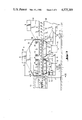
- FIG. 1 is an overall view in perspective of an embodiment of a bending device according to the invention
- FIG. 2 is a view in longitudinal section of another embodiment of a bending device, according to the invention, preceded by a heating furnace and followed by a tempering station;
- FIG. 3 is a view in longitudinal section of another embodiment of the bending device incorporated in an installation for making bent glass plates;
- FIG. 4 is a view in vertical section along line IV--IV of FIG. 3;
- FIGS. 5 and 6 are diagrams illustrating the operation of adjusting the height of the pivoting axis of the frame carrying the shaping bed.
- FIG. 1 illustrates the basic structure of a bending device according to the invention.
- Glass plates 1 to be bent are heated to the bending temperature in a heating furnace (not shown here), in which they are conveyed in the direction of arrow F by conveyer rollers 2 which are driven in rotation.
- the heating furnace is followed by a bending station.
- This bending station comprises a shaping bed confined in a heated enclosure (not shown) and consisting of a plurality of rotating shaping elements 3 on which glass plates 1 rest. Under the effect of their own weight, glass plates 1 take the shape of the shaping bed.
- Each rotating shaping element 3 comprises a flexible woven metallic tubular sheath 4, resistant to twisting, and rotatably driven around a rigid curve rod 5.
- All the curved rods have the same shape and the same radius of curvature.
- Each has a curved middle part and ends 6 which are straight in relation to this median part so that they are coaxial and form a pivoting axis S--S' around which the curved rod can be pivoted.
- These ends 6 of the curved rods are mounted to pivot in beams 8 parallel to the conveying direction of glass plates 1, these beams constituting a support frame for the shaping bed.
- each curved rod 5 is provided with a crank 9 which serves to pivot the rod in the desired angular position.
- a roller 10 is mounted on the end of each crank 9 and all rollers 10 associated with all curved rods 5 of the shaping bed are guided in a U-shaped rail, having a rail portion referenced as 11 in a first part A of the shaping bed, and a rail portion referenced as 12 in a second part B downstream from the first part A.
- curved rods 5 are all inclined differently, the inclination increasing progressively from one rod to the next, thus forming a shaping bed whose curvature in the crosswise direction perpendicular to the direction of advance of glass plates 1 steadily increases.
- the shaping bed is concave.
- first curved rod 5 of the bending bed i.e. referenced rod 5'
- first curved rod 5 of the bending bed i.e. referenced rod 5'
- following rods 5 are increasingly inclined, in the shaping direction, to the last rod 5 of portion A, this latter rod referenced 5", which has the maximum inclination determining the curvature desired for glass plates 1.
- rail portion 11 is mounted to pivot around a transverse joint 14 located at its upstream end, which makes it possible to incline the rail portion in the direction of the progression of the glass plates in relation to the frame determined by beams 8, in particular in relation to the horizontal if this frame is placed horizontally.
- a lever 16 of a toggle joint mechanism 17, 18, and 19 described in detail below, serves to provide pivoting of rail portion 11 around joint 14.
- Rail portion 12 in which end rollers 10 of cranks 9 of curved rods 5 travel in part B of the installation is hinged on a pin 20 belonging to the downstream end of rail portion 11. It can be varied in height while remaining in the same angular inclination, particularly while remaining horizontal, by action on lever 16 which controls the deformation of two contiguous parallelograms.
- the first parallelogram is formed by a connecting rod 18, two links 17 each fastened to two points distant from rail portion 12, this portion of rail portion 12 constituting the fourth side of the parallelogram.
- the second is formed by connecting rod 18 common to the two parallelograms, two arms 19, one of which is extended by lever 16, and a fourth side constituted by an unreferenced portion of a fixed frame located between two stationary points 21 for fastening of the two arms 19.
- toggle joint mechanism 17, 18 and 19 it would, of course, be possible to use other means making possible a progressive adjustment in height of rail portion 12 and a progressive inclination of rail portion 11.
- Curved rods 5'" of part B of the shaping bed are mounted to pivot in a frame 22 which is hinged around joints 23 on the downstream end of beams 8 of the frame of part A of the shaping bed.
- This frame 22 is mounted on a toggle joint mechanism 24, 25 and 26 of the same type as that which carries rail portion 12.
- this mechanism 24, 25 and 26 can be operated by a lever 27, which moves frame 22 up and down with no change in inclination, and which also modifies the inclination of the frame formed by beams 8 of first part A of the shaping bed by making beams 8 pivot around joints 28, located on a transverse horizontal axis XX' at the head of the installation.
- Lever 16 and toggle joint mechanism 17, 18 and 19 make it possible not only to adjust the radius of curvature of the shaping bed, but also to orient the curvature, i.e., to make the bed concave or convex.
- Lever 27 serves to adjust the height of portion B of the shaping bed and consequently the inclination of portion A of said bed, so that, for given widths of glass plates 1, either the line placed lengthwise to the center of said plates 1 or lengthwise the edges remains at a constant level.
- Bearings 28 of beams 8 which constitute the frame carrying curved rods 5 in portion A of said shaping bed are adjustable in height. To do this, they are supported by rods 33 of lifting jacks 34. Rods 33 can be moved by action on drive shaft 35.
- joint 14 of U-shaped rail portion 11 is mounted on a rod 37 of a lifting jack 38, said rod being able to go up or down by action on drive shaft 39.
- Flexible tubular sheaths 4 which are resistant to twisting and cover curved rods 5, are driven in rotation around rods 5 via sprockets 31 to which the sheaths are fixed.
- the sprockets engage in one or more drive chains 30.
- FIG. 2 shows, in longitudinal section along the median axis, a unit of an installation for making bent glass plates, including a second embodiment of a bending device according to the invention.
- This bending device is preceded by a heating furnace 58, equipped with rollers 2 for conveying the glass plates in the direction of arrow F, and followed by a tempering station 59.
- the elements of the bending station are shown in FIG. 1, i.e., mainly shaping elements 3 formed by curved rods 5 surrounded by flexible tubular sheaths 4 driven in rotation.
- shaping elements 3 determine a shaping bed in two parts: a first part A in which the curvature presented to glass plates 1 is initially practically zero, and progressively increases until it becomes maximum at the level of the last element 5" of this part A, and a second part B in which the curvature is constant and equal to the curvature established by the last shaping element 5" of part A.
- curved rods 5 are mounted to pivot in beams 42 placed lengthwise and in second part B they are mounted in beams 43.
- Beams 43 are hinged on the downstream end of beams 42 by a joint 44, beams 43 of part B of the shaping bed rest on joints 45 and 46 mounted on rods 47 and 48 of lifting jacks 49 and 50 operated by shafts 51 and 52.
- Beams 42 of part A of the shaping bed are supported, on the one hand, by joint 44 and, on the other hand, at their upstream end on a joint 53 located on a transverse horizontal axis YY' and mounted on rod 54 of a lifting jack 55 operated by a shaft 56.
- Jacks 49, 50 and 55 rest on fixed frame 57, as do the other parts of the installation, particularly heating furnace 58 and tempering station 59.
- Tempering station 59 includes means for support of the bent glass sheets, i.e., curved rods 5 surrounded by flexible tubular sheaths, having the same orientation as rods 5 of part B of the shaping bed, and blowing boxes 60 and 61 delivering cooling air to the sheaths through tubular nozzles 62.
- FIGS. 3 and 4 Another advantageous embodiment of a bending device according to the invention is shown in FIGS. 3 and 4.
- the beams which support the curved rods of second part B of the shaping bed are referenced 63 and form a frame that rests on pillars 64.
- the beams that support the curved rods of first part A of the shaping bed are referenced 65 and are mounted on joints 66, 67.
- Joints 67 are located on a transverse horizontal axis ZZ'.
- Each front or upstream joint 67 is carried by a rod 69 of a lifting jack 70 operated by a shaft 71, while each back or downstream joint 66 is carried by a pillar 68.
- the assembly of pillars 64 and 68 and of jack 70 rests on a frame 75 which is carried by jacks 73 and 74.
- cranks fitted on the curved rods, the rollers, and the support rails necessary for orientation of the curved rods still exist in this embodiment, but they are not shown to avoids cluttering the drawing.
- funnel-shaped enclosures 78 closed at their upper end by perforated plates 80, fed by feed pipes 79 with pressurized gas, generally air, heated to about 650° C.
- pressurized gas generally air, heated to about 650° C.
- the hot air emitted vertically from the bottom to the top through the perforations in plates 80, is directed toward the lower face of the glass plates and thus forms a homogeneous, uniform flow of gas providing support to said glass plates.
- the excess pressure in enclosures 78 is about 10 to 60 mm water gage (10-60 mm WG) or 100 to 600 Pa
- the perforations through plates 80 have a diameter of 12 to 15 mm and are evenly distributed in both the crosswise and lengthwise directions with the same pitch of 25 to 35 mm
- the distance between perforated plates 80 and the glass plates is such that at the level of the glass the static pressure is negligible in comparison with the dynamic pressure, which corresponds to distances between plates 80 and glass plates on the order of 100 to 300 mm
- there is obtained on the glass plates a homogeneous, uniform pressure on the order of 2 to 30 mm WG which makes it possible to take over 20 to 80% of the weight of the glass plates, thus reducing the pressure exerted by the shaping elements on the plates and notably improving the optical quality.
- a hot gas aspiration hood 82 Above the shaping bed is mounted a hot gas aspiration hood 82. This hood 82 is connected to an evacuation pipe 83 with a conduit (not shown) which recycles the recovered gas.
- This gas receives additional heat and is reinjected into enclosures 78 by feed pipes 79.
- heating elements 86 fastened to a support 87 that is adjustably secured by holding lugs 88.
- heating furnace 58 Upstream from the bending station itself is heating furnace 58 in which the glass plates, conveyed flat on cylindrical conveyer rollers 2, are heated to bending temperature.
- Tempering station 59 with blowing boxes 60 and 61 deivering tempering gas by tubular nozzles 62 is placed downstream from the bending station.
- FIG. 4 shows other details relating to the design and mounting of the bending station shown in FIG. 3.
- crank 9 provided at the end of first curved rod 5' provided with roller 10 which is guided in U-shaped rail portion 11.
- U-shaped rail portion 11 is mounted to pivot on joint 14 fastened to rod 37 of jack 38.
- Tubular sheath 4 rotates around curved rod 5', this sheath 4 being fixed to a sprocket 31 which engages with a chain 30, this sprocket 31 being placed on the outside of enclosure 84 which encloses the bending station.
- jack 38 rests on frame 75 which, for its part, can be adjusted in height by lifting jacks 73.
- Heating elements 86 are shown in FIG. 4. These heating elements are carried by supports 87, secured by lugs 88 which are fastened by washers 89 and nuts 90 in the side walls of enclosure 84.
- FIGS. 5 and 6 illustrate the steps performed in using the device of the invention.
- FIG. 5 shows a glass plate 1 of width b 1 to be bent with a radius of curvature R.
- FIG. 6 shows a glass plate 1' of width b 2 less than b 1 which also is to be bent with a radius of curvature R.
- conveying plane E is determined by the upper generatrices of cylindrical conveyer rollers 2.
- the bearings of said rod 5' are lifted a height h1 so that the lengthwise edges 92 of glass plate 1, which is located in the curved portion of curved rod 5' which is slightly lowered in relation to its ends because of the inclination and curvature of said rod, remain at the level of conveying plane E.
- the central zone of the glass plate which fits the curved median part of rod 5, sags below the level of edges 92.
- last rod 5" of rods 5 of portion A of the shaping bed has its bearings offset upward a height h 2 above conveying plane E, substantially greater than h 1 .
- FIG. 6 shows, a glass plate 1' of width b 2 less than b 1 is curved, the bearings of curved rod 5', inclined to exhibit upward concavity, should be lifted a distance H 1 greater than h 1 so that edges 93 of plate 1' remain at the level of initial conveying plane E.
- distance H 2 of the upward offset of the bearings of curved rod 5" at the downstream end of part A of the shaping bed, is clearly greater than H 1 and h 2 .
- the transverse pivoting axis of the frame supporting the shaping bed can be adjusted in height, and said frame can be inclined by pivoting around this transverse axis making it possible progressively to increase or decrease the height of the bearings of the curved rods, in the direction of the curvature of the shaping bed.
Landscapes
- Chemical & Material Sciences (AREA)
- Engineering & Computer Science (AREA)
- Materials Engineering (AREA)
- Organic Chemistry (AREA)
- Re-Forming, After-Treatment, Cutting And Transporting Of Glass Products (AREA)
- Joining Of Glass To Other Materials (AREA)
Applications Claiming Priority (2)
| Application Number | Priority Date | Filing Date | Title |
|---|---|---|---|
| FR8317830A FR2554437B1 (fr) | 1983-11-09 | 1983-11-09 | Dispositif de bombage de plaques de verre |
| FR8317830 | 1983-11-09 |
Publications (1)
| Publication Number | Publication Date |
|---|---|
| US4575389A true US4575389A (en) | 1986-03-11 |
Family
ID=9293944
Family Applications (1)
| Application Number | Title | Priority Date | Filing Date |
|---|---|---|---|
| US06/669,795 Expired - Fee Related US4575389A (en) | 1983-11-09 | 1984-11-09 | Device for bending glass plates |
Country Status (12)
| Country | Link |
|---|---|
| US (1) | US4575389A (fi) |
| EP (1) | EP0148043B1 (fi) |
| JP (1) | JPS60171238A (fi) |
| KR (1) | KR850003879A (fi) |
| BR (1) | BR8405698A (fi) |
| CA (1) | CA1244243A (fi) |
| DE (1) | DE3471294D1 (fi) |
| ES (1) | ES8600174A1 (fi) |
| FI (1) | FI75332C (fi) |
| FR (1) | FR2554437B1 (fi) |
| PT (1) | PT79476B (fi) |
| YU (1) | YU43938B (fi) |
Cited By (8)
| Publication number | Priority date | Publication date | Assignee | Title |
|---|---|---|---|---|
| US4787504A (en) * | 1986-10-06 | 1988-11-29 | Ppg Industries, Inc. | Adjustable radius conveyor roll |
| US5176733A (en) * | 1988-12-27 | 1993-01-05 | Ford Motor Company | Method and apparatus for directed energy glass heating |
| US5395415A (en) * | 1993-12-13 | 1995-03-07 | Libbey-Owens-Ford Co. | Method and apparatus for conveying and shaping glass sheets |
| EP0909742A1 (de) * | 1997-10-10 | 1999-04-21 | Ingenieurgemeinschaft WSP Prof. Dr.-Ing. C.Kramer Prof. H.J. Gerhardt, M.Sc. | Vorrichtung zum Biegen von Flachglas |
| US6076374A (en) * | 1995-08-25 | 2000-06-20 | Tambest Oy | Bending mold for bending glass sheets |
| WO2001032569A1 (en) * | 1999-11-01 | 2001-05-10 | Uniglass Engineering Oy | Method and apparatus for bending glass |
| US20020170317A1 (en) * | 1999-11-01 | 2002-11-21 | Uniglass Engineering Oy | Method of bending glass, and a glass-bending mould |
| US20060179885A1 (en) * | 2003-02-21 | 2006-08-17 | Pauli Reunamaki | Method and apparatus for bending and tempering or heat-strengthening a bidirectionally curved glass panel |
Families Citing this family (4)
| Publication number | Priority date | Publication date | Assignee | Title |
|---|---|---|---|---|
| US4670036A (en) * | 1986-06-04 | 1987-06-02 | Libbey-Owens-Ford Co. | Conveying, supporting and shaping glass sheets |
| FR2604992B1 (fr) * | 1986-10-01 | 1988-12-02 | Saint Gobain Vitrage | Bombage et trempe de plaques de verre defilant sur un lit de conformation courbe dans la direction de defilement |
| EP0634371B1 (de) * | 1993-07-15 | 1999-04-21 | Cristales Automatrices De Jalisco, S.A. | Verfahren und Vorrichtung zum dreidimensionalen Verformen von Platten, insbesondere Glasscheiben |
| BR9906620A (pt) * | 1998-06-19 | 2000-09-19 | Asahi Glass Co Ltd | Método e aparelho de conformação em curva para uma chapa de vidro |
Citations (3)
| Publication number | Priority date | Publication date | Assignee | Title |
|---|---|---|---|---|
| US3223498A (en) * | 1962-02-27 | 1965-12-14 | Pittsburgh Plate Glass Co | Heat treatment of conveyed glass and apparatus therefor |
| US4054438A (en) * | 1975-05-30 | 1977-10-18 | Saint-Gobain Industries | Method and apparatus for curving sheets in the plastic state |
| US4139359A (en) * | 1977-11-02 | 1979-02-13 | Ppg Industries, Inc. | Method and apparatus for shaping glass sheets by roll forming |
Family Cites Families (1)
| Publication number | Priority date | Publication date | Assignee | Title |
|---|---|---|---|---|
| FR2342947A1 (fr) * | 1976-03-05 | 1977-09-30 | Saint Gobain | Procede et dispositif pour le bombage de feuilles de verre |
-
1983
- 1983-11-09 FR FR8317830A patent/FR2554437B1/fr not_active Expired
-
1984
- 1984-11-08 PT PT79476A patent/PT79476B/pt not_active IP Right Cessation
- 1984-11-08 KR KR1019840006997A patent/KR850003879A/ko not_active Application Discontinuation
- 1984-11-08 JP JP59234220A patent/JPS60171238A/ja active Pending
- 1984-11-08 ES ES537493A patent/ES8600174A1/es not_active Expired
- 1984-11-08 BR BR8405698A patent/BR8405698A/pt unknown
- 1984-11-08 YU YU1883/84A patent/YU43938B/xx unknown
- 1984-11-08 FI FI844401A patent/FI75332C/fi not_active IP Right Cessation
- 1984-11-09 US US06/669,795 patent/US4575389A/en not_active Expired - Fee Related
- 1984-11-09 EP EP84402260A patent/EP0148043B1/fr not_active Expired
- 1984-11-09 CA CA000467508A patent/CA1244243A/fr not_active Expired
- 1984-11-09 DE DE8484402260T patent/DE3471294D1/de not_active Expired
Patent Citations (3)
| Publication number | Priority date | Publication date | Assignee | Title |
|---|---|---|---|---|
| US3223498A (en) * | 1962-02-27 | 1965-12-14 | Pittsburgh Plate Glass Co | Heat treatment of conveyed glass and apparatus therefor |
| US4054438A (en) * | 1975-05-30 | 1977-10-18 | Saint-Gobain Industries | Method and apparatus for curving sheets in the plastic state |
| US4139359A (en) * | 1977-11-02 | 1979-02-13 | Ppg Industries, Inc. | Method and apparatus for shaping glass sheets by roll forming |
Cited By (15)
| Publication number | Priority date | Publication date | Assignee | Title |
|---|---|---|---|---|
| US4787504A (en) * | 1986-10-06 | 1988-11-29 | Ppg Industries, Inc. | Adjustable radius conveyor roll |
| US5176733A (en) * | 1988-12-27 | 1993-01-05 | Ford Motor Company | Method and apparatus for directed energy glass heating |
| US5395415A (en) * | 1993-12-13 | 1995-03-07 | Libbey-Owens-Ford Co. | Method and apparatus for conveying and shaping glass sheets |
| WO1995016639A1 (en) * | 1993-12-13 | 1995-06-22 | Libbey-Owens-Ford Co. | Conveying and shaping glass sheets |
| US6301933B1 (en) | 1995-08-25 | 2001-10-16 | Tambest Oy | Method for bending glass sheets |
| US6076374A (en) * | 1995-08-25 | 2000-06-20 | Tambest Oy | Bending mold for bending glass sheets |
| DE19744875A1 (de) * | 1997-10-10 | 1999-11-25 | Kramer Carl | Vorrichtung zum Biegen von Flachglas |
| DE19744875C2 (de) * | 1997-10-10 | 2000-03-30 | Kramer Carl | Vorrichtung zum Biegen von Flachglas |
| EP0909742A1 (de) * | 1997-10-10 | 1999-04-21 | Ingenieurgemeinschaft WSP Prof. Dr.-Ing. C.Kramer Prof. H.J. Gerhardt, M.Sc. | Vorrichtung zum Biegen von Flachglas |
| WO2001032569A1 (en) * | 1999-11-01 | 2001-05-10 | Uniglass Engineering Oy | Method and apparatus for bending glass |
| US20020152769A1 (en) * | 1999-11-01 | 2002-10-24 | Uniglass Engineering Oy | Method and apparatus for bending glass |
| US20020170317A1 (en) * | 1999-11-01 | 2002-11-21 | Uniglass Engineering Oy | Method of bending glass, and a glass-bending mould |
| US6786065B2 (en) | 1999-11-01 | 2004-09-07 | Uniglass Engineering Oy | Method and apparatus for bending glass |
| US7059155B2 (en) * | 1999-11-01 | 2006-06-13 | Uniglass Engineering Oy | Method of bending glass |
| US20060179885A1 (en) * | 2003-02-21 | 2006-08-17 | Pauli Reunamaki | Method and apparatus for bending and tempering or heat-strengthening a bidirectionally curved glass panel |
Also Published As
| Publication number | Publication date |
|---|---|
| BR8405698A (pt) | 1985-09-10 |
| FR2554437A1 (fr) | 1985-05-10 |
| YU43938B (en) | 1989-12-31 |
| EP0148043B1 (fr) | 1988-05-18 |
| CA1244243A (fr) | 1988-11-08 |
| PT79476A (fr) | 1984-12-01 |
| FR2554437B1 (fr) | 1986-01-31 |
| FI844401A0 (fi) | 1984-11-08 |
| ES537493A0 (es) | 1985-10-16 |
| DE3471294D1 (en) | 1988-06-23 |
| JPS60171238A (ja) | 1985-09-04 |
| ES8600174A1 (es) | 1985-10-16 |
| YU188384A (en) | 1988-06-30 |
| FI844401L (fi) | 1985-05-10 |
| PT79476B (fr) | 1986-08-05 |
| FI75332C (fi) | 1988-06-09 |
| KR850003879A (ko) | 1985-06-29 |
| EP0148043A1 (fr) | 1985-07-10 |
| FI75332B (fi) | 1988-02-29 |
Similar Documents
| Publication | Publication Date | Title |
|---|---|---|
| US4557745A (en) | Bending of glass sheets on a shaping bed consisting of rotating elements | |
| US4773925A (en) | Adjustable roll forming arrangement | |
| US4292065A (en) | Method and apparatus for shaping thermoplastic sheet material | |
| US4820327A (en) | Bending and tempering of glass plates advancing on a shaping bed curved in the direction of advance | |
| US4226608A (en) | Method and apparatus for curving glass sheets | |
| US4575389A (en) | Device for bending glass plates | |
| CA1069702A (en) | Glass sheet supporting and conveying apparatus | |
| US4540425A (en) | Apparatus for bending and tempering of thermoplastic sheets of different curvatures | |
| EP0719736B1 (en) | Conveyor roll device for preliminarily bending sheet glass | |
| EP0249161B1 (en) | Adjustable quenching apparatus for tempering hot glass sheets | |
| JPH03150232A (ja) | ガラス板を曲げる方法及び装置 | |
| US4976762A (en) | Method and apparatus for bending and tempering a glass sheet | |
| JP2837540B2 (ja) | ガラス板搬送曲げ加工装置 | |
| US3869269A (en) | Method and apparatus for press shaping heat-softened sheets | |
| US4054438A (en) | Method and apparatus for curving sheets in the plastic state | |
| US5201928A (en) | Glass sheet forming method and apparatus | |
| US4318728A (en) | Double link arrangement for press bending molds and method of press shaping glass sheets | |
| KR101186542B1 (ko) | 크로스 곡률을 갖는 글래스 시트 성형 장치 및 방법 | |
| FI82025C (fi) | Foerfarande och anordning foer att boeja en glasskiva. | |
| US4028086A (en) | Apparatus for bending and tempering glass sheets by differential cooling | |
| US3856499A (en) | Shaping heat-softened glass sheets by roll forming | |
| US3929441A (en) | Roll forming heat-softened glass sheets | |
| JPH02221133A (ja) | 熱軟化可能な板材料の造形方法及び装置 | |
| US4043783A (en) | Press shaping glass sheets | |
| JPS5929530B2 (ja) | 可塑状態の板状物の湾曲方法および装置 |
Legal Events
| Date | Code | Title | Description |
|---|---|---|---|
| AS | Assignment |
Owner name: SAINT-GOBAIN VITRAGE, LES MIROIRS" 18 AVENUE D`AL Free format text: ASSIGNMENT OF ASSIGNORS INTEREST.;ASSIGNORS:HALBERSCHMIDT, FRIEDRICH;AUDI, JOSEF;SCHUBERT, GERHARD;REEL/FRAME:004469/0012 Effective date: 19841114 |
|
| FEPP | Fee payment procedure |
Free format text: PAYOR NUMBER ASSIGNED (ORIGINAL EVENT CODE: ASPN); ENTITY STATUS OF PATENT OWNER: LARGE ENTITY |
|
| FPAY | Fee payment |
Year of fee payment: 4 |
|
| REMI | Maintenance fee reminder mailed | ||
| LAPS | Lapse for failure to pay maintenance fees | ||
| FP | Lapsed due to failure to pay maintenance fee |
Effective date: 19940313 |
|
| STCH | Information on status: patent discontinuation |
Free format text: PATENT EXPIRED DUE TO NONPAYMENT OF MAINTENANCE FEES UNDER 37 CFR 1.362 |