US4571482A - Electric resistance heater assembly for soldering and desoldering devices - Google Patents
Electric resistance heater assembly for soldering and desoldering devices Download PDFInfo
- Publication number
- US4571482A US4571482A US06/546,173 US54617383A US4571482A US 4571482 A US4571482 A US 4571482A US 54617383 A US54617383 A US 54617383A US 4571482 A US4571482 A US 4571482A
- Authority
- US
- United States
- Prior art keywords
- area
- resistance element
- distal end
- strips
- areas
- Prior art date
- Legal status (The legal status is an assumption and is not a legal conclusion. Google has not performed a legal analysis and makes no representation as to the accuracy of the status listed.)
- Expired - Fee Related
Links
- 238000005476 soldering Methods 0.000 title claims abstract description 9
- 229910052751 metal Inorganic materials 0.000 claims abstract description 19
- 239000002184 metal Substances 0.000 claims abstract description 19
- 239000011810 insulating material Substances 0.000 claims abstract description 13
- 239000011888 foil Substances 0.000 claims abstract description 12
- 230000007423 decrease Effects 0.000 claims abstract description 6
- 238000010438 heat treatment Methods 0.000 claims 1
- 230000007704 transition Effects 0.000 abstract description 2
- 239000010445 mica Substances 0.000 description 12
- 229910052618 mica group Inorganic materials 0.000 description 12
- 230000000712 assembly Effects 0.000 description 3
- 238000000429 assembly Methods 0.000 description 3
- 238000010276 construction Methods 0.000 description 3
- 229910018487 Ni—Cr Inorganic materials 0.000 description 2
- VNNRSPGTAMTISX-UHFFFAOYSA-N chromium nickel Chemical compound [Cr].[Ni] VNNRSPGTAMTISX-UHFFFAOYSA-N 0.000 description 2
- 230000000694 effects Effects 0.000 description 2
- 238000005530 etching Methods 0.000 description 1
- 230000017525 heat dissipation Effects 0.000 description 1
- 238000000034 method Methods 0.000 description 1
- 229910001220 stainless steel Inorganic materials 0.000 description 1
- 239000010935 stainless steel Substances 0.000 description 1
Images
Classifications
-
- B—PERFORMING OPERATIONS; TRANSPORTING
- B23—MACHINE TOOLS; METAL-WORKING NOT OTHERWISE PROVIDED FOR
- B23K—SOLDERING OR UNSOLDERING; WELDING; CLADDING OR PLATING BY SOLDERING OR WELDING; CUTTING BY APPLYING HEAT LOCALLY, e.g. FLAME CUTTING; WORKING BY LASER BEAM
- B23K3/00—Tools, devices, or special appurtenances for soldering, e.g. brazing, or unsoldering, not specially adapted for particular methods
- B23K3/02—Soldering irons; Bits
- B23K3/03—Soldering irons; Bits electrically heated
- B23K3/0338—Constructional features of electric soldering irons
-
- B—PERFORMING OPERATIONS; TRANSPORTING
- B23—MACHINE TOOLS; METAL-WORKING NOT OTHERWISE PROVIDED FOR
- B23K—SOLDERING OR UNSOLDERING; WELDING; CLADDING OR PLATING BY SOLDERING OR WELDING; CUTTING BY APPLYING HEAT LOCALLY, e.g. FLAME CUTTING; WORKING BY LASER BEAM
- B23K3/00—Tools, devices, or special appurtenances for soldering, e.g. brazing, or unsoldering, not specially adapted for particular methods
- B23K3/04—Heating appliances
- B23K3/047—Heating appliances electric
-
- H—ELECTRICITY
- H05—ELECTRIC TECHNIQUES NOT OTHERWISE PROVIDED FOR
- H05B—ELECTRIC HEATING; ELECTRIC LIGHT SOURCES NOT OTHERWISE PROVIDED FOR; CIRCUIT ARRANGEMENTS FOR ELECTRIC LIGHT SOURCES, IN GENERAL
- H05B3/00—Ohmic-resistance heating
- H05B3/10—Heating elements characterised by the composition or nature of the materials or by the arrangement of the conductor
Definitions
- This invention relates to electric heater assemblies and more specifically to an assembly using a thin foil resistance element in a novel enclosure and configuration to control the location and intensity of heat generated.
- Applicant is unaware of any heater assembly adapted to be used in hand held soldering or desoldering devices which utilizes a resistance element of thin foil etched in a configuration and encased in a metal enclosure that results in maximum heat dissipation at the working tip end but limits the transfer of heat to the terminal ends.
- Heater assemblies for soldering or desoldering devices are well known and typically consists of resistance wire wound about the tool remote from the tip or about a bobbin or the like in which the tool is removably mounted, the ends of the resistance wire then being connected to terminals which in turn are connected to a source of electric current.
- This construction does not result in a concentration of high heat at the tip end and away from the terminals as is most desirable but rather in a bulky device which has the heat distributed substantially equally over a wide area.
- Heater assemblies housing a resistance element positioned between layers of insulating material all encased in a sheet metal enclosure are well known as shown in U.S. Pat. Nos.
- an electric heater assembly comprising an elongated resistance element formed from a thin flat metal foil having three connected areas of different resistance, the differeing resistance being caused by the different widths of the areas.
- the first area to which terminals are attached, is the widest and acts as a heat sink.
- the second area decreases in width to the first area and acts as a transition area between the first and third areas.
- the first and second areas include first and second separated portions for providing electrical current to the first area and returning it therefrom.
- the first area includes first and second strips respectively connected to the first and second portions of the second area.
- the strips extend adjacent a first side edge of the third area in a side-by-side relationship to the distal end of the resistance element and then back towards the second area to a position where they are connected to one another.
- the side-by-side position of the strips at the distal end of the third area facilitates application of heat to a work.
- An assembly for enclosing the resistance element to electrically isolate it from the work includes layers of insulating material between which the resistance element positioned and a sheet metal housing enclosure.
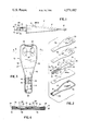
- FIG. 1 is a perspective view of the electric heater assembly of the present invention connected to a hand grip
- FIG. 2 is a separated, perspective view of parts included in the preferred embodiment
- FIG. 3 is a top view of the electric heater assembly having a portion thereof broken away
- FIG. 4 is an enlarged cross-sectional view taken along the lines 4--4 of FIG. 3.
- 10 indicates generally a soldering or desoldering type tool having the electric heater assembly 12 of the present invention held by a hand grip 14.
- the hand grip 14 would typically have a switch 16 in series with a pair of contacts 20 for connecting the heater assembly 12 to an electrical plug 18.
- the heater assembly 12 includes an elongated resistance or heater element 22 of very thin nickel-chromium foil which is formed into the novel shape disclosed, as best seen in FIG. 2, by an etching process. More specifically, the element 22 has a proximal end 11 and a distal end 13 and includes three distinct areas of differing resistance which, of course, results in three different intensities of heat generated.
- the first or terminal areas 24, 26 are identical and extend from one end of the element to a point 28, 30 where the sides begin to taper inwardly.
- the second or intermediate areas 32, 34 vary in area and extend from the points 28, 30 respectively, to the point 36, 38 where the width of the element is substantially the same.
- the third or working areas 40, 42 extend as a narrow strip of constant width from a first position generally comprising the points 36, 38 respectively, to a second position comprising the tip end 44 where they are joined to form a continuous ribbon of foil with the first and second areas where the width of the thrid area should be no greater than the smallest width of the second area.
- the working areas 40, 42 extend in parallel, spaced apart relationship to each other from the points 36, 38 along side edge 15, distal end 13, side edge 17, and then to tip end 44 via side edge 19 to form a substantially U-shape.
- the particular operating characteristics of the heater element 22 and the function of the various areas 22, 24, 32, 34 and 40, 42 will be more fully described later.
- the heater element 22 is positioned between two thin sheets of mica 46, 48 which have the same general shape as the heater element 22 only slightly larger and in effect overlap the edges of the heater element 22.
- the upper mica sheet 46 has two similar apertures 50 therethrough which, when positioned on the heater element 22, expose the terminal areas 24, 26.
- the lower mica sheet 48 has no apertures and entirely covers the underside of the heater element 22 when positioned adjacent it.
- the upper mica sheet 46, heater element 22 and lower mica sheet 48 are placed in a container 52 having a continuous upstanding side wall 54 around the edge of a bottom 56 in the same general configuration as the mica sheets 46, 48.
- a top 58 for the container 52 is also provided having the same shape as the mica sheet 48 and two apertures 60 which, when the top 58 is positioned over the mica sheet 46, are in registry with the apertures 50 to expose the terminal areas 24, 26.
- the container 52 and top 58 are typically constructed of a metal such as stainless steel.
- the mica sheet 48 is positioned in the container 52 adjacent the bottom 56.
- the heater element 22 is then positioned on the mica sheet 48 such that a space 62 exists between the periphery of the heater element 22 and the side wall 54 of the container 52 to effectively prevent contact therebetween.
- the mica sheet 46 is positioned over the heater element 22 followed by the top 58 with their respective apertures 50, 60 in registry above terminals 24, 26.
- the top edge 64 of the side wall 54 is then rolled over or crimped onto the top 58 to thereby compress the heater element 22 and mica sheets 46, 48 into good heat conductive relationship with each other and the top 58 and more significantly the bottom 56 of the container 52 to complete the heater assembly 12.
- the working area 40, 42 and tip end 44 will generate the most heat due to the narrow width thereof and this heat will be transmitted to the narrow end 66 of the container 52 which is the working end or area that will be brought into contact with the work (not shown) for soldering, desoldering or other purposes.
- the heat generated in the second or intermediate area 32 diminishes gradually as the width thereof increases from points 36, 38 to points 28, 30.
- the heat generated at the terminal areas 24, 26 is minimal and as such does not effect the means of making electrical contact therewith such as contacts 20 nor does it radiate heat of a degree that would make the hand grip uncomfortable to hold.
- the tapered nature of the intermediate areas 32, 34 acts as a buffer zone between high, intense heat generated at the tip 44 and adjacent working area 40, 42, and the terminal 24, 26 which acts to blend the heat generated and prevent heat from being transferred from the work areas to the terminal area or withdrawn from the work itself and transferred to the terminal areas.
- the terminal areas 24, 26 function as a heat sink.
- third or working areas 40, 42 may be in a lower plane than the first or terminal areas 24, 26 where second or intermediate areas 32, 34 bend downwardly from the third area to the first area.
Landscapes
- Engineering & Computer Science (AREA)
- Mechanical Engineering (AREA)
- Surface Heating Bodies (AREA)
- Resistance Heating (AREA)
Priority Applications (7)
| Application Number | Priority Date | Filing Date | Title |
|---|---|---|---|
| US06/546,173 US4571482A (en) | 1983-10-27 | 1983-10-27 | Electric resistance heater assembly for soldering and desoldering devices |
| GB08426645A GB2149278B (en) | 1983-10-27 | 1984-10-22 | Electric heater assembley |
| IT23315/84A IT1177037B (it) | 1983-10-27 | 1984-10-25 | Gruppo elettrico di riscaldamento |
| CA000466345A CA1234180A (fr) | 1983-10-27 | 1984-10-25 | Element chauffant electrique |
| JP59225612A JPS612289A (ja) | 1983-10-27 | 1984-10-26 | 電気ヒ−タ−アセンブリ− |
| FR8416398A FR2554301B1 (fr) | 1983-10-27 | 1984-10-26 | Ensemble chauffant electrique et fer a souder le comprenant |
| DE19843439339 DE3439339A1 (de) | 1983-10-27 | 1984-10-26 | Elektrische heizeinheit |
Applications Claiming Priority (1)
| Application Number | Priority Date | Filing Date | Title |
|---|---|---|---|
| US06/546,173 US4571482A (en) | 1983-10-27 | 1983-10-27 | Electric resistance heater assembly for soldering and desoldering devices |
Publications (1)
| Publication Number | Publication Date |
|---|---|
| US4571482A true US4571482A (en) | 1986-02-18 |
Family
ID=24179188
Family Applications (1)
| Application Number | Title | Priority Date | Filing Date |
|---|---|---|---|
| US06/546,173 Expired - Fee Related US4571482A (en) | 1983-10-27 | 1983-10-27 | Electric resistance heater assembly for soldering and desoldering devices |
Country Status (7)
| Country | Link |
|---|---|
| US (1) | US4571482A (fr) |
| JP (1) | JPS612289A (fr) |
| CA (1) | CA1234180A (fr) |
| DE (1) | DE3439339A1 (fr) |
| FR (1) | FR2554301B1 (fr) |
| GB (1) | GB2149278B (fr) |
| IT (1) | IT1177037B (fr) |
Cited By (5)
| Publication number | Priority date | Publication date | Assignee | Title |
|---|---|---|---|---|
| US4752670A (en) * | 1985-06-25 | 1988-06-21 | Pace Incorporated | Bobbin assembly for a soldering/desoldering device using an etched foil heater |
| US5475199A (en) * | 1993-12-22 | 1995-12-12 | Buchanan; R. Craig | Planar electric heater with enclosed U-shaped thick film heating element |
| FR2765128A1 (fr) * | 1997-06-25 | 1998-12-31 | Guilbert Express Sa | Fer a souder electrique compact a haut rendement |
| US6719188B2 (en) | 2001-07-24 | 2004-04-13 | International Business Machines Corporation | Rework methods for lead BGA/CGA |
| KR102226033B1 (ko) * | 2020-02-20 | 2021-03-11 | 홍진표 | 전기인두기용 인두팁 및 그 제작방법 |
Families Citing this family (3)
| Publication number | Priority date | Publication date | Assignee | Title |
|---|---|---|---|---|
| FR2601543B1 (fr) * | 1986-07-11 | 1992-05-15 | Intertechnique Sa | Paroi rigide chauffante et application a la constitution d'un generateur electrique |
| DE10130511C5 (de) * | 2001-06-25 | 2011-04-14 | Bleckmann Gmbh & Co. Kg | Heizvorrichtung zum Erhitzen eines flüssigen oder gasförmigen Mediums |
| GB2377402B (en) * | 2001-07-12 | 2004-05-12 | Agilent Technologies Inc | Improved diebond strip |
Citations (22)
| Publication number | Priority date | Publication date | Assignee | Title |
|---|---|---|---|---|
| US953393A (en) * | 1908-12-09 | 1910-03-29 | Gen Electric | Resistance unit. |
| CH52848A (de) * | 1910-09-22 | 1912-01-02 | Prometheus Fabrik Elektrischer | Widerstandsleiter für elektrische Heizkörper |
| US1046887A (en) * | 1909-05-13 | 1912-12-10 | Gen Electric | Electric heating device. |
| US1067869A (en) * | 1912-05-27 | 1913-07-22 | Pacific Electric Heating Company | Electric heating unit. |
| US1075517A (en) * | 1909-10-13 | 1913-10-14 | Westinghouse Electric & Mfg Co | Electrical heater element and method of making the same. |
| US1154409A (en) * | 1909-10-16 | 1915-09-21 | American Electrical Heater Co | Electrical heating unit. |
| US1158488A (en) * | 1910-02-11 | 1915-11-02 | Westinghouse Electric & Mfg Co | Electrical apparatus. |
| US1171104A (en) * | 1911-01-30 | 1916-02-08 | Cutler Hammer Mfg Co | Electric heater. |
| US1203044A (en) * | 1911-01-03 | 1916-10-31 | Charles Phelps | Sectional hot-water furnace. |
| US1384467A (en) * | 1920-01-27 | 1921-07-12 | Electrothermal Company | Bandage |
| US1496077A (en) * | 1923-06-14 | 1924-06-03 | Bleadon Dun Company | Soldering iron |
| US1520913A (en) * | 1922-10-16 | 1924-12-30 | Beehler Steel Products Company | Electric soldering iron and method of making the same |
| US1890780A (en) * | 1929-08-26 | 1932-12-13 | Gray Percy | Heating element structure and process of making the same |
| US1904594A (en) * | 1930-05-15 | 1933-04-18 | Gen Electric | Electric heater |
| US2144724A (en) * | 1937-08-07 | 1939-01-24 | Ralph E Lawrence | Vulcanizer |
| US2214084A (en) * | 1938-12-13 | 1940-09-10 | Lovice Herman | Cloth erasing tool |
| US2250602A (en) * | 1939-08-21 | 1941-07-29 | Paul W Pierce | Honey uncapping knife |
| US2432800A (en) * | 1946-03-02 | 1947-12-16 | Silex Co | Heating element and method of making same |
| US2473183A (en) * | 1947-07-16 | 1949-06-14 | Bates Mfg Co | Electrically conductive fabric |
| US2553762A (en) * | 1946-11-01 | 1951-05-22 | Gyuris John | Electrical heating element and method of making the same |
| GB1166528A (en) * | 1967-07-24 | 1969-10-08 | Langley London Ltd | Improvements in and relating to Heating Elements and Resistors |
| US3808573A (en) * | 1973-01-16 | 1974-04-30 | Emerson Electric Co | Electric heater assemblies |
Family Cites Families (5)
| Publication number | Priority date | Publication date | Assignee | Title |
|---|---|---|---|---|
| DE837906C (de) * | 1948-05-31 | 1952-05-02 | Max Haefliger | Elektrischer Loetkolben |
| US2935593A (en) * | 1957-11-22 | 1960-05-03 | Norman C Fulmer | Directly-heated tip for a soldering tool |
| US3526750A (en) * | 1967-06-02 | 1970-09-01 | William J Siegel | Thermal tool |
| GB1308708A (en) * | 1970-12-09 | 1973-03-07 | Langley London Ltd | Resistors and heating elements |
| LU72577A1 (fr) * | 1975-01-31 | 1975-10-08 |
-
1983
- 1983-10-27 US US06/546,173 patent/US4571482A/en not_active Expired - Fee Related
-
1984
- 1984-10-22 GB GB08426645A patent/GB2149278B/en not_active Expired
- 1984-10-25 CA CA000466345A patent/CA1234180A/fr not_active Expired
- 1984-10-25 IT IT23315/84A patent/IT1177037B/it active
- 1984-10-26 JP JP59225612A patent/JPS612289A/ja active Granted
- 1984-10-26 FR FR8416398A patent/FR2554301B1/fr not_active Expired
- 1984-10-26 DE DE19843439339 patent/DE3439339A1/de not_active Withdrawn
Patent Citations (22)
| Publication number | Priority date | Publication date | Assignee | Title |
|---|---|---|---|---|
| US953393A (en) * | 1908-12-09 | 1910-03-29 | Gen Electric | Resistance unit. |
| US1046887A (en) * | 1909-05-13 | 1912-12-10 | Gen Electric | Electric heating device. |
| US1075517A (en) * | 1909-10-13 | 1913-10-14 | Westinghouse Electric & Mfg Co | Electrical heater element and method of making the same. |
| US1154409A (en) * | 1909-10-16 | 1915-09-21 | American Electrical Heater Co | Electrical heating unit. |
| US1158488A (en) * | 1910-02-11 | 1915-11-02 | Westinghouse Electric & Mfg Co | Electrical apparatus. |
| CH52848A (de) * | 1910-09-22 | 1912-01-02 | Prometheus Fabrik Elektrischer | Widerstandsleiter für elektrische Heizkörper |
| US1203044A (en) * | 1911-01-03 | 1916-10-31 | Charles Phelps | Sectional hot-water furnace. |
| US1171104A (en) * | 1911-01-30 | 1916-02-08 | Cutler Hammer Mfg Co | Electric heater. |
| US1067869A (en) * | 1912-05-27 | 1913-07-22 | Pacific Electric Heating Company | Electric heating unit. |
| US1384467A (en) * | 1920-01-27 | 1921-07-12 | Electrothermal Company | Bandage |
| US1520913A (en) * | 1922-10-16 | 1924-12-30 | Beehler Steel Products Company | Electric soldering iron and method of making the same |
| US1496077A (en) * | 1923-06-14 | 1924-06-03 | Bleadon Dun Company | Soldering iron |
| US1890780A (en) * | 1929-08-26 | 1932-12-13 | Gray Percy | Heating element structure and process of making the same |
| US1904594A (en) * | 1930-05-15 | 1933-04-18 | Gen Electric | Electric heater |
| US2144724A (en) * | 1937-08-07 | 1939-01-24 | Ralph E Lawrence | Vulcanizer |
| US2214084A (en) * | 1938-12-13 | 1940-09-10 | Lovice Herman | Cloth erasing tool |
| US2250602A (en) * | 1939-08-21 | 1941-07-29 | Paul W Pierce | Honey uncapping knife |
| US2432800A (en) * | 1946-03-02 | 1947-12-16 | Silex Co | Heating element and method of making same |
| US2553762A (en) * | 1946-11-01 | 1951-05-22 | Gyuris John | Electrical heating element and method of making the same |
| US2473183A (en) * | 1947-07-16 | 1949-06-14 | Bates Mfg Co | Electrically conductive fabric |
| GB1166528A (en) * | 1967-07-24 | 1969-10-08 | Langley London Ltd | Improvements in and relating to Heating Elements and Resistors |
| US3808573A (en) * | 1973-01-16 | 1974-04-30 | Emerson Electric Co | Electric heater assemblies |
Non-Patent Citations (2)
| Title |
|---|
| "Thermofoil Heat Fusers", Bulletin TF-5, Minco Products Inc., Minneapolis, Minn., Form 7Y615, revised 3/20/75, 4 pages. |
| Thermofoil Heat Fusers , Bulletin TF 5, Minco Products Inc., Minneapolis, Minn., Form 7Y615, revised 3/20/75, 4 pages. * |
Cited By (6)
| Publication number | Priority date | Publication date | Assignee | Title |
|---|---|---|---|---|
| US4752670A (en) * | 1985-06-25 | 1988-06-21 | Pace Incorporated | Bobbin assembly for a soldering/desoldering device using an etched foil heater |
| US5475199A (en) * | 1993-12-22 | 1995-12-12 | Buchanan; R. Craig | Planar electric heater with enclosed U-shaped thick film heating element |
| FR2765128A1 (fr) * | 1997-06-25 | 1998-12-31 | Guilbert Express Sa | Fer a souder electrique compact a haut rendement |
| WO1999000214A1 (fr) * | 1997-06-25 | 1999-01-07 | Guilbert-Express | Fer a souder electrique compact a haut rendement |
| US6719188B2 (en) | 2001-07-24 | 2004-04-13 | International Business Machines Corporation | Rework methods for lead BGA/CGA |
| KR102226033B1 (ko) * | 2020-02-20 | 2021-03-11 | 홍진표 | 전기인두기용 인두팁 및 그 제작방법 |
Also Published As
| Publication number | Publication date |
|---|---|
| DE3439339A1 (de) | 1985-05-15 |
| GB8426645D0 (en) | 1984-11-28 |
| IT1177037B (it) | 1987-08-26 |
| FR2554301A1 (fr) | 1985-05-03 |
| JPS612289A (ja) | 1986-01-08 |
| JPS6255276B2 (fr) | 1987-11-19 |
| IT8423315A0 (it) | 1984-10-25 |
| GB2149278A (en) | 1985-06-05 |
| CA1234180A (fr) | 1988-03-15 |
| IT8423315A1 (it) | 1986-04-25 |
| GB2149278B (en) | 1986-11-05 |
| FR2554301B1 (fr) | 1988-09-09 |
Similar Documents
| Publication | Publication Date | Title |
|---|---|---|
| US5376089A (en) | Electrosurgical instrument | |
| US3980861A (en) | Electrically heated miniature thermal implement | |
| US4571482A (en) | Electric resistance heater assembly for soldering and desoldering devices | |
| GB2181629A (en) | Ptc heating device | |
| JPS62125543U (fr) | ||
| US4904203A (en) | Device for connecting a wire to a motor terminal | |
| US4697066A (en) | Electric hair curling waved with improved heating element arrangement | |
| DE1123059B (de) | Schutzschalter fuer elektrische Kochplatten | |
| US2036461A (en) | Permanent waving apparatus | |
| JPH0713196Y2 (ja) | 電気接続子 | |
| ATE231319T1 (de) | Elektrisches koch- und toastgerät und elektrische elementen dazu | |
| DE69907264D1 (de) | Elektrisches koch- und toastgerät sowie zugehörige elektrische elemente | |
| JPS6466901A (en) | Ptc element | |
| JPH0644058Y2 (ja) | 導電膜接続端子 | |
| DE69009159T2 (de) | Haarpflegegerät. | |
| US2723575A (en) | Wire stripper | |
| EP0181733A1 (fr) | Commutateur électrique chirurgical | |
| DE9413707U1 (de) | Hitze-Kauter | |
| JPH0346461Y2 (fr) | ||
| RU2210148C1 (ru) | Средство соединения проводов с проводником из мягкого материала (варианты) | |
| KR100268351B1 (ko) | 전자가열밀봉장치 | |
| CH97853A (de) | Elektrisches Plätteisen. | |
| US2133163A (en) | Electric heater | |
| US2193086A (en) | Permanent waving | |
| JPH0235197Y2 (fr) |
Legal Events
| Date | Code | Title | Description |
|---|---|---|---|
| AS | Assignment |
Owner name: PACE, INC., LAUREL, MD. A MD CORP. Free format text: ASSIGNMENT OF ASSIGNORS INTEREST.;ASSIGNOR:VOGEL, ALAN D.;REEL/FRAME:004189/0528 Effective date: 19831010 |
|
| AS | Assignment |
Owner name: PACE, INCORPORATED, A CORP OF MARYLAND Free format text: MERGER;ASSIGNOR:PACE INCORPORATED, A CORP OF DELAWARE;REEL/FRAME:004489/0140 Effective date: 19850326 |
|
| REMI | Maintenance fee reminder mailed | ||
| LAPS | Lapse for failure to pay maintenance fees | ||
| STCH | Information on status: patent discontinuation |
Free format text: PATENT EXPIRED DUE TO NONPAYMENT OF MAINTENANCE FEES UNDER 37 CFR 1.362 |
|
| FP | Lapsed due to failure to pay maintenance fee |
Effective date: 19900218 |