US4569040A - Electronic switching system having a time division multiplex switch controller address by central control unit - Google Patents
Electronic switching system having a time division multiplex switch controller address by central control unit Download PDFInfo
- Publication number
- US4569040A US4569040A US06/571,442 US57144284A US4569040A US 4569040 A US4569040 A US 4569040A US 57144284 A US57144284 A US 57144284A US 4569040 A US4569040 A US 4569040A
- Authority
- US
- United States
- Prior art keywords
- address
- data
- bus
- time division
- division multiplex
- Prior art date
- Legal status (The legal status is an assumption and is not a legal conclusion. Google has not performed a legal analysis and makes no representation as to the accuracy of the status listed.)
- Expired - Fee Related
Links
Images


Classifications
-
- H—ELECTRICITY
- H04—ELECTRIC COMMUNICATION TECHNIQUE
- H04Q—SELECTING
- H04Q11/00—Selecting arrangements for multiplex systems
- H04Q11/04—Selecting arrangements for multiplex systems for time-division multiplexing
- H04Q11/0407—Selecting arrangements for multiplex systems for time-division multiplexing using a stored programme control
Definitions
- the present invention relates to electronic switching systems for telecommunication exchanges and more particularly to time division multiplex (TDM) address and control systems for the control of the passage of data along highways in the system.
- TDM time division multiplex
- a time division multiplex address and controller system for a telecommunication exchange, said control system comprising a time division multiplex digital switch controller, a common control computer, a plurality of shelves of equipment containing telephony groups, in which the time division multiplex digital switch control is addressed by the computer as one of said shelves of equipment to insert control information into said time division multiplex switch controller to control the passage of information in between the shelves and between the shelves the common control computer.
- FIG. 1 shows the position of the digital switch controller (DSC) in a typical system such as described in our co-pending British patent application No.: 8323782,
- FIG. 2 shows the digital switch controller connected into a typical electronic switching system such as described in our co-pending British application No.: 8323782,
- FIG. 3 shows a block circuit diagram of the DSC controller
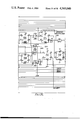
- FIGS. 4A (1-12) and 4B (1-10), when assembled together per FIGS. 4A and 4B, show a circuit diagram of the DSC.
- FIGS. 5 to 10 show timing diagrams explaining the operation of the controller
- FIG. 11 shows in block diagram form the control section of the shelf interface of FIG. 2,
- FIG. 12 shows an interface circuit for use in the present invention in block diagram form
- FIGS. 13A to O when assembled per FIG. 13, shows the circuit of FIG. 12 in greater detail
- FIGS. 14 to 19 show timing diagrams associated with the circuit of FIGS. 12 and 13 and
- FIG. 20 shows a command structure table according to the present invention.
- the computer 10 issues instructions to the controller 20 along bus 12.
- the controller 20 may for example be connected into a digital telecommunication exchange as described in the above co-pending patent application. The operation of the controller 20 will be so described by way of example.
- the computer inserts two addresses in a connection table in the controller 20.
- One is the address of the card to transmit the information and can go in AB0 or AB1 and the other is the address of the receive register in the controller. This causes information to be passed from a card in the system to the receive register so that the information is readable by the computer 10.
- the controller interfaces signals between the computer bus 12 and the Intershelf bus (108, 110, 112) in a manner illustrated by the timing diagrams of FIGS. 5 to 10.
- signal codes are given in this specification such as for example DS60 these refer to codes allocated by Data General for their Nova computer range.
- the DSC 20 communicates with the Computer 10 via a 16 bit DATA 0-15 bus (12) and with the telephony group shelves along the intershelf bus, ISB, via three sixteen bit buses i.e. AB0 1-15, AB1 1-15 and DB0-15, buses 108, 110, 112--FIG. 2.
- a command word is received along the DATA 0-15 bus 12 from the computer 10 and inserted into the correct time slot and onto the correct address bus in the connection table as signified by the computer.
- Data is also received and transmitted along the DATA 0-15 bus on the common control shelf and along the DB0-15 on the ISB 112.
- FIG. 6 shows relative timing of these signals.
- controller 20 is shown in block diagram form in greater detail. Signals (Data bits 0-15) are received from controller on bus 12. Except where otherwise indicated each line represents a 16 bit bus, other bus widths being indicated by numerals.
- the controller 20 comprises a command register 202 the output of which is connected to two address buffers 204, 206 for AB0 and AB1.
- the outputs of these buffers 204, 206 are connected respectively to AB0 and AB1 random access memories 208, 210; the entry of information into these memories being controlled by a random access memory address multiplex circuit 212 clocked by an address counter 214 driven by the A clock, the multiplexer 212 being controlled by an entry address register 216 which receives address instructions from bus 12.
- Addresses output from memory 208 are latched by a latch 218 and subsequently clocked to an address bus driver 220.
- a read back address circuit 222 is connected to bus 108.
- the outputs of circuit 222 are connected to transmit upper register and transmit lower register circuits 224, 226.
- the transmit upper and lower registers 224, 226 are also connected to data bus drivers upper and lower 228, 230 to enable data from bus 12 to be transmitted onto the upper and lower bytes of bus 112.
- RAM 210 is connected to a latch 232 and to an AB1 driver 234 to output address information onto address bus 110.
- Bus 110 is connected to a read back address circuit 236 which is connected to the bus drivers 228, 230.
- the address buses 112 (Data bus upper and lower) are connected to a receive register 238 which outputs data to an input/output bus driver 240 the output of which is connected to bus 12.
- the entry address register 216 dictates the address at which data is written into both RAM's 208 and 210.
- the multiplexer 212 provides a 10 bit address for both RAMS 208, 210. Also information stored in the RAM's 208, 210 can be read out and fed via input/output bus driver 240 back to the computer via bus 12 for checking.
- address information output on address buses 108 and 110 can be read back via circuits 222 and 236 respectively and fed via drivers 228, 230 and receive register 238 to driver 240 and hence back to the computer for checking.
- connection table is a Time Division Multiplexed addressing system consisting of 512 slots each 32 bits wide. Each slot is divided into two 16 bit blocks, one of which is loaded into the AB0 bus and the other onto the AB1 bus. Shown below is the bit allocation for the 16 bit command word which is loaded onto the address buses.
- the connection table logic is RAM based (see FIG. 4B) with two ways of accessing the RAM.
- the addresses used to access the RAM are output from a 2-1 multiplexer 212 which selects 1 of 2 available addresses.
- the first address which is used to access the RAM during a read cycle is generated by a 1-512 cyclic counter (time slot counter) clocked by the positive going edge of D clock, which clock is actually a combination of D and A clock as described hereinafter (see FIG. 9).
- the second address available is the address which is latched into the Entry Address latch on receipt of a Data out C DAT0C and DS60 signals from the computer as mentioned hereinafter.
- addresses are selected by DCLK where the output of the cyclic counter is enabled during the negative cycle of the clock and the Entry Address output on the positive cycle of the clock. Both addresses are used to access the RAM but during a read cycle it is only the data accessed by the cyclic counter address which is enabled onto the AB0 and AB1 buses.
- the address output by the Entry Address Registers 216, and enabled by the 2-1 multiplexer 212, is used to access the RAM and the data in the command registers in the computer 10 is written into the RAM by a WE signal derived from DCLK, as shown in FIG. 8.
- the 2-1 multiplexer 212 permanently selects the output from the cyclic counter and a "no operation" (NOP) is written into all locations in the connection table RAM. This operation clears the connection table of all commands.
- Time slots 512 and 1 to 7 are called the Immediate Field and are treated differently to the other time slots 8-511.
- Time slots 8-511 are the non-immediate field and are used continuously for card reading whereas time slots 512 and 1 to 7 are used for the control of hardware--e.g. operating relays.
- the AB0 and AB1 drivers 220 which buffer commands onto the ISB are diabled; when the count of 8 is decoded, the drivers are enabled. Therefore under normal operating conditions the commands in the Immediate Field are not output onto the ISB. If the input output pulse I0PLS, signal is received from the computer, the AB0 and AB1 buffer disabling logic is disabled and during the next full immediate field the commands in slots 512 and 1 to 7 are output on the ISB 112.
- the immediate field is used to generate special commands to receive and transmit status or to Up and Down cards.
- Output onto the ISB is a signal called TS0 which is the 512 count decode signal from the counter clocked by DCLK to give a pulse once every frame.
- the data present on DATA 6-15 from the computer is loaded into the Entry Address Register 216 (FIG. 3).
- the information received is an address in the range 1 to 512 and is the connection table slot number selected by the computer for the next command word output from the computer.
- the contents of the register is used to address the AB0 or AB1 rams on receipt of a DOA60 or DOB60 as described previously.
- the functionality of the DSC is indicated by the state of an UP/DOWN latch. If a CLR and DS61 signal is received from the computer, the UP/DOWN latch is set to DOWN. This occurs when the computer decides to disable the DSC due possibly to a malfunction. An LED is illuminated indicating the DSC is DOWN. If a STRT and DS61 signal is received the UP/DOWN latch is set to UP and the LED is extinguished. The UP/DOWN latch is set to UP when the equipment is brought into use by the reset signal IORST. With reference to FIG. 2 if the A side DSC is "DOWN" the B side DSC takes over control of the exchange.
- DATA 0-15 The data from the Common Control Computer, DATA 0-15, is latched into the Transmit Registers on receipt of DATOC and DS61 signals from the computer.
- the data latched in the Receive Register is output to the computer as DATA 0-15 on receipt of DATIA and DS61 signals from the computer.
- the DSC 20 monitors the six device select bits DS0-5.
- the computer 10 sends codes 60 and 61, the signals DS60 and DS61 are generated and the following DSC functions are enabled.
- the busy flag, SELB is set when an IOPLS signal is received to indicate that an immediate field operation is pending, the flag is cleared at the end of the immediate field.
- SELB is also set for the duration of a System Normalise, SYN.
- the power supply voltage for the system is +5 ⁇ 0.25 Volts. This supply is decoupled by a 15 ⁇ F bulk decoupling capacitor and a 10 nF capacitor at every dilic (dual-in-line integrated circuit) position.
- the shelf interface circuit 104 receives addresses on the two address buses 108, 110. Five bits of each address are decoded in decode circuits 302, 304 to produce respective shelf enable circuits on lines 306, 308. The remaining 11 bits are buffered in buffers 310, 312 and used as shelf bus addresses on shelf address buses B AB0 and B AB1.
- Data is received and transmitted on bus 112 as two sets of eight bits designated upper and lower bytes on buses 314, 316. These are received and transmitted by bi-directional buffers 318,320, onto from and to shelf buses B DATA BUS UPPER 322 and B DATA BUS LOWER 324. Control of the passage of data from buffers 318,320 is by a DOUT UPPER and DOUT LOWER signal.
- the interface circuit 1 of the present invention is shown interposed between the telephony groups 100 via the shelf bus S1 and the intershelf bus 108, 110, 112.
- the interface circuit comprises an address comparator 22 connected via an AND gate 3 to a timing control circuit 24 which selectively controls the operation of a latching circuit 25, a decoding circuit 26 and an output controller 27.
- the interface circuit as shown in FIGS. 12 and 13 is preferably constructed as an uncommitted logic array (ULA) and will be referred to as such for purposes of timing sequences.
- ULA uncommitted logic array
- the card address contained in the address word (bits 5-9) is compared in comparator 22 to the hard-wired TDM motherboard card slot address (CAD 1-5). If all bits match then the SHELF ENABLE initiates a command cycle via AND gate 23.
- 5 of the latches in the 6 bit latch 25 are "transparent" level triggered latches.
- the clock is CARD ENABLE gated with DCLOCK to ensure that input data is stable during the whole clock period.
- the other data latch has a PRESET input to ensure the card does not power up in the DOWN mode.
- the command structure is as shown in the table of FIG. 20.
- the decode section generates the appropriate demands to the output control section.
- the MODE pin is normally hard wired to a specific logic function depending on the function of the associated cards.
- the MODE pin when high, permits an extra transmit pulse to be generated during a receive cycle for codec applications, codecs being used to convert analogue signals for use by the telephone subscribers.
- a two time slot delay is introduced by delay 28 for generation of the receive pulse at the correct time.
- ULA's For a codec of a telephony group, two ULA's are required.
- the transceive command given to either ULA generates a TRANSMIT pulse and a RECEIVE pulse.
- the RECEIVE is required from the other ULA to control the other half of the data bus for the receive data.
- the ADVANCE RECEIVE OUT and ADVANCE RECEIVE IN are cross coupled between the two ULA's.
- the MODE pin on each ULA is set high.
- the MODE pin is set low which effectively gates together ADVANCE RECEIVE OUT and ADVANCE RECEIVE IN internally.
- UP and DOWN commands are fully decoded from all six address bits (10-15) and a single bit latch in output control 27 is set accordingly.
- the timing control On receipt of CARD ENABLE, the timing control produces two enables and a clock.
- the clock is a combination of CARD ENABLE and DCLOCK for the 6 bit latch as hereinbefore described.
- the enables are:
- CLOCKED ENABLE As the output from the 6 bit latch 5 does not change until the next command, CLOCKED ENABLE allows only one ADVANCE RECEIVE OUT pulse to be generated if AB15 is high or DOUT if AB15 is low.
- Command DOUT tells the shelf interface in FIG. 1 to drive out or to receive information. DOUT can be common or DOUT upper or DOUT lower. If DOUT upper is selected, information is only transmitted on the upper portion of the highway and vice versa if DOUT lower is selected, information is only transmitted on the lower portion of the highway.
- the output control 27 gates together the output demands from the decode section and the timing control signals.
- ADVANCE RECEIVE IN or internally gated ADVANCE RECEIVE OUT clocked out by ACLOCK as a 1/2 clock pulse.
- Open collector driver for DOWN light emitting diode indicator to indicate when the card is non-operational.
- DCLK and DCLK* are continuously attempting to reset the Bus Transceiver Enable BTE latch and inhibit the output gate.
- Either DOUT, ADVANCE RECEIVE IN or ADVANCE RECEIVE OUT (with MODE set low) suppress DCLK* and DCLK for one cycle and permit ACLK* to initiate the pulse and set the BTE latch.
Landscapes
- Engineering & Computer Science (AREA)
- Computer Networks & Wireless Communication (AREA)
- Use Of Switch Circuits For Exchanges And Methods Of Control Of Multiplex Exchanges (AREA)
- Exchange Systems With Centralized Control (AREA)
- Data Exchanges In Wide-Area Networks (AREA)
- Communication Control (AREA)
- Selective Calling Equipment (AREA)
- Sub-Exchange Stations And Push- Button Telephones (AREA)
Applications Claiming Priority (4)
| Application Number | Priority Date | Filing Date | Title |
|---|---|---|---|
| GB8301325 | 1983-01-18 | ||
| GB838301325A GB8301325D0 (en) | 1983-01-18 | 1983-01-18 | Interface circuits |
| GB8301326 | 1983-01-18 | ||
| GB838301326A GB8301326D0 (en) | 1983-01-18 | 1983-01-18 | Electronic switching system |
Publications (1)
| Publication Number | Publication Date |
|---|---|
| US4569040A true US4569040A (en) | 1986-02-04 |
Family
ID=26284944
Family Applications (1)
| Application Number | Title | Priority Date | Filing Date |
|---|---|---|---|
| US06/571,442 Expired - Fee Related US4569040A (en) | 1983-01-18 | 1984-01-17 | Electronic switching system having a time division multiplex switch controller address by central control unit |
Country Status (10)
| Country | Link |
|---|---|
| US (1) | US4569040A (da) |
| EP (1) | EP0122684B1 (da) |
| JP (1) | JPH0638675B2 (da) |
| AU (1) | AU562716B2 (da) |
| CA (1) | CA1212442A (da) |
| DE (1) | DE3472197D1 (da) |
| DK (1) | DK166340C (da) |
| IE (1) | IE55080B1 (da) |
| NO (1) | NO167180C (da) |
| NZ (1) | NZ206850A (da) |
Cited By (2)
| Publication number | Priority date | Publication date | Assignee | Title |
|---|---|---|---|---|
| US5283786A (en) * | 1990-11-21 | 1994-02-01 | Alcatel N.V. | Burst architecture time-division switch and equipment access module for use in a switch of this kind |
| GB2303274A (en) * | 1995-07-11 | 1997-02-12 | Fujitsu Ltd | Switching apparatus |
Families Citing this family (2)
| Publication number | Priority date | Publication date | Assignee | Title |
|---|---|---|---|---|
| US4608685A (en) * | 1984-04-30 | 1986-08-26 | Northern Telecom Limited | Packet and circuit switched communications network |
| GB8515347D0 (en) * | 1985-06-18 | 1985-07-17 | Plessey Co Plc | Telecommunications exchanges |
Citations (4)
| Publication number | Priority date | Publication date | Assignee | Title |
|---|---|---|---|---|
| US3996566A (en) * | 1974-12-16 | 1976-12-07 | Bell Telephone Laboratories, Incorporated | Shift and rotate circuit for a data processor |
| US4187399A (en) * | 1978-06-05 | 1980-02-05 | Bell Telephone Laboratories, Incorporated | Call state processor for a time division switching system |
| US4408323A (en) * | 1981-06-29 | 1983-10-04 | Bell Telephone Laboratories, Incorporated | Processor facilities for integrated packet and voice switching |
| US4430733A (en) * | 1977-11-07 | 1984-02-07 | Post Office | Switching of digital signals |
Family Cites Families (1)
| Publication number | Priority date | Publication date | Assignee | Title |
|---|---|---|---|---|
| GB2007942B (en) * | 1977-11-07 | 1982-04-28 | Post Office | Switching of digital signals |
-
1984
- 1984-01-13 EP EP84300193A patent/EP0122684B1/en not_active Expired
- 1984-01-13 DE DE8484300193T patent/DE3472197D1/de not_active Expired
- 1984-01-17 IE IE90/84A patent/IE55080B1/en not_active IP Right Cessation
- 1984-01-17 NO NO840162A patent/NO167180C/no unknown
- 1984-01-17 NZ NZ206850A patent/NZ206850A/en unknown
- 1984-01-17 CA CA000445406A patent/CA1212442A/en not_active Expired
- 1984-01-17 US US06/571,442 patent/US4569040A/en not_active Expired - Fee Related
- 1984-01-18 DK DK022484A patent/DK166340C/da not_active IP Right Cessation
- 1984-01-18 AU AU23564/84A patent/AU562716B2/en not_active Expired
- 1984-01-18 JP JP59006990A patent/JPH0638675B2/ja not_active Expired - Lifetime
Patent Citations (4)
| Publication number | Priority date | Publication date | Assignee | Title |
|---|---|---|---|---|
| US3996566A (en) * | 1974-12-16 | 1976-12-07 | Bell Telephone Laboratories, Incorporated | Shift and rotate circuit for a data processor |
| US4430733A (en) * | 1977-11-07 | 1984-02-07 | Post Office | Switching of digital signals |
| US4187399A (en) * | 1978-06-05 | 1980-02-05 | Bell Telephone Laboratories, Incorporated | Call state processor for a time division switching system |
| US4408323A (en) * | 1981-06-29 | 1983-10-04 | Bell Telephone Laboratories, Incorporated | Processor facilities for integrated packet and voice switching |
Cited By (4)
| Publication number | Priority date | Publication date | Assignee | Title |
|---|---|---|---|---|
| US5283786A (en) * | 1990-11-21 | 1994-02-01 | Alcatel N.V. | Burst architecture time-division switch and equipment access module for use in a switch of this kind |
| GB2303274A (en) * | 1995-07-11 | 1997-02-12 | Fujitsu Ltd | Switching apparatus |
| GB2303274B (en) * | 1995-07-11 | 1999-09-08 | Fujitsu Ltd | Switching apparatus |
| US6011793A (en) * | 1995-07-11 | 2000-01-04 | Fujitsu Limited | Switching apparatus for simultaneously switching a plurality of switch units, with each switch unit including storage regions corresponding to other switch units |
Also Published As
| Publication number | Publication date |
|---|---|
| NO167180B (no) | 1991-07-01 |
| DK166340C (da) | 1993-08-23 |
| EP0122684A1 (en) | 1984-10-24 |
| DK22484D0 (da) | 1984-01-18 |
| JPS59188294A (ja) | 1984-10-25 |
| AU2356484A (en) | 1984-07-19 |
| IE840090L (en) | 1984-07-18 |
| DK166340B (da) | 1993-04-05 |
| CA1212442A (en) | 1986-10-07 |
| AU562716B2 (en) | 1987-06-18 |
| EP0122684B1 (en) | 1988-06-15 |
| DE3472197D1 (en) | 1988-07-21 |
| NZ206850A (en) | 1987-11-27 |
| DK22484A (da) | 1984-07-19 |
| IE55080B1 (en) | 1990-05-23 |
| JPH0638675B2 (ja) | 1994-05-18 |
| NO840162L (no) | 1984-07-19 |
| NO167180C (no) | 1991-10-09 |
Similar Documents
| Publication | Publication Date | Title |
|---|---|---|
| US5596540A (en) | Serial to parallel and parallel to serial architecture for a RAM based FIFO memory | |
| US4736409A (en) | Control data transmission system for private branch exchange | |
| US4733390A (en) | Data transmission system | |
| US4345325A (en) | Message-interchange circuitry for microprocessors linked by synchronous communication network | |
| US5822776A (en) | Multiplexed random access memory with time division multiplexing through a single read/write port | |
| US5088089A (en) | Apparatus for programmably accessing and assigning time slots in a time division multiplexed communication system | |
| CA1273124A (en) | Ram memory overlay gate array circuit | |
| US4569040A (en) | Electronic switching system having a time division multiplex switch controller address by central control unit | |
| EP0419750B1 (en) | Distribution mechanism for establishing communications between user interfaces of a communication system | |
| EP0493138B1 (en) | Memory circuit | |
| GB2134753A (en) | Electronic switching system | |
| US4942573A (en) | Loosely coupled parallel network simulator | |
| US6751201B1 (en) | Data exchange system and method of data exchange | |
| AU613153B2 (en) | Memory addressing system | |
| SU1649506A1 (ru) | Программируемый управл ющий модуль | |
| KR100233100B1 (ko) | 시분할 액서스방식을 채용한 다중 프로세서의 데이타 통신장치 | |
| KR100288752B1 (ko) | 가입자 보드와 가입자 제어 인터페이스 보드간의 정합장치 | |
| GB2234372A (en) | Mass memory device | |
| KR0144825B1 (ko) | 시스템 제어기의 실시간 클럭 제어기 | |
| KR950003970B1 (ko) | 디지탈 전자교환기의 피시엠 데이타 접속장치 | |
| US20030120839A1 (en) | Micro controller development system | |
| KR0153016B1 (ko) | 전전자 교환기용 시공간 분할 스위칭 회로 | |
| KR0169789B1 (ko) | 클럭주기가 다른 블럭들의 데이타 전송방법 및 회로 | |
| KR0181485B1 (ko) | 데이터 통신용 데이터 버퍼링 장치 | |
| SU1725210A1 (ru) | Программируемый формирователь управл ющих воздействий микропроцессорной системы |
Legal Events
| Date | Code | Title | Description |
|---|---|---|---|
| AS | Assignment |
Owner name: PLESSEY OVERSEAS LIMITED VICARAGE LANE, ILFORD ESS Free format text: ASSIGNMENT OF ASSIGNORS INTEREST.;ASSIGNORS:O TOOLE, ANTHONY J. P.;BOOT, GORDON P.;REEL/FRAME:004221/0997 Effective date: 19840111 |
|
| AS | Assignment |
Owner name: GEC PLESSEY TELECOMMUNICATIONS LIMITED, P.O. BOX 5 Free format text: ASSIGNMENT OF ASSIGNORS INTEREST.;ASSIGNOR:PLESSEY OVERSEAS LIMITED;REEL/FRAME:005142/0442 Effective date: 19890119 |
|
| FPAY | Fee payment |
Year of fee payment: 4 |
|
| AS | Assignment |
Owner name: GEC PLESSEY TELECOMMUNICATIONS LIMITED,, ENGLAND Free format text: ASSIGNMENT OF ASSIGNORS INTEREST.;ASSIGNOR:GPT INTERNATIONAL LIMITED;REEL/FRAME:005195/0115 Effective date: 19890930 Owner name: GPT INTERNATIONAL LIMITED Free format text: CHANGE OF NAME;ASSIGNOR:GEC PLESSEY TELECOMMUNICATIONS LIMITED;REEL/FRAME:005217/0147 Effective date: 19890917 |
|
| FPAY | Fee payment |
Year of fee payment: 8 |
|
| REMI | Maintenance fee reminder mailed | ||
| LAPS | Lapse for failure to pay maintenance fees | ||
| FP | Lapsed due to failure to pay maintenance fee |
Effective date: 19980204 |
|
| STCH | Information on status: patent discontinuation |
Free format text: PATENT EXPIRED DUE TO NONPAYMENT OF MAINTENANCE FEES UNDER 37 CFR 1.362 |