US4548355A - Device for regulating heating capacity of a heat exchanger - Google Patents
Device for regulating heating capacity of a heat exchanger Download PDFInfo
- Publication number
- US4548355A US4548355A US06/172,945 US17294580A US4548355A US 4548355 A US4548355 A US 4548355A US 17294580 A US17294580 A US 17294580A US 4548355 A US4548355 A US 4548355A
- Authority
- US
- United States
- Prior art keywords
- heat exchanger
- temperature
- heat
- output
- actuating means
- Prior art date
- Legal status (The legal status is an assumption and is not a legal conclusion. Google has not performed a legal analysis and makes no representation as to the accuracy of the status listed.)
- Expired - Lifetime
Links
Images

Classifications
-
- F—MECHANICAL ENGINEERING; LIGHTING; HEATING; WEAPONS; BLASTING
- F28—HEAT EXCHANGE IN GENERAL
- F28D—HEAT-EXCHANGE APPARATUS, NOT PROVIDED FOR IN ANOTHER SUBCLASS, IN WHICH THE HEAT-EXCHANGE MEDIA DO NOT COME INTO DIRECT CONTACT
- F28D1/00—Heat-exchange apparatus having stationary conduit assemblies for one heat-exchange medium only, the media being in contact with different sides of the conduit wall, in which the other heat-exchange medium is a large body of fluid, e.g. domestic or motor car radiators
- F28D1/02—Heat-exchange apparatus having stationary conduit assemblies for one heat-exchange medium only, the media being in contact with different sides of the conduit wall, in which the other heat-exchange medium is a large body of fluid, e.g. domestic or motor car radiators with heat-exchange conduits immersed in the body of fluid
- F28D1/04—Heat-exchange apparatus having stationary conduit assemblies for one heat-exchange medium only, the media being in contact with different sides of the conduit wall, in which the other heat-exchange medium is a large body of fluid, e.g. domestic or motor car radiators with heat-exchange conduits immersed in the body of fluid with tubular conduits
- F28D1/053—Heat-exchange apparatus having stationary conduit assemblies for one heat-exchange medium only, the media being in contact with different sides of the conduit wall, in which the other heat-exchange medium is a large body of fluid, e.g. domestic or motor car radiators with heat-exchange conduits immersed in the body of fluid with tubular conduits the conduits being straight
- F28D1/05316—Assemblies of conduits connected to common headers, e.g. core type radiators
-
- B—PERFORMING OPERATIONS; TRANSPORTING
- B60—VEHICLES IN GENERAL
- B60H—ARRANGEMENTS OF HEATING, COOLING, VENTILATING OR OTHER AIR-TREATING DEVICES SPECIALLY ADAPTED FOR PASSENGER OR GOODS SPACES OF VEHICLES
- B60H1/00—Heating, cooling or ventilating devices
- B60H1/00642—Control systems or circuits; Control members or indication devices for heating, cooling or ventilating devices
- B60H1/00814—Control systems or circuits characterised by their output, for controlling particular components of the heating, cooling or ventilating installation
- B60H1/00878—Control systems or circuits characterised by their output, for controlling particular components of the heating, cooling or ventilating installation the components being temperature regulating devices
- B60H1/00885—Controlling the flow of heating or cooling liquid, e.g. valves or pumps
-
- F—MECHANICAL ENGINEERING; LIGHTING; HEATING; WEAPONS; BLASTING
- F28—HEAT EXCHANGE IN GENERAL
- F28F—DETAILS OF HEAT-EXCHANGE AND HEAT-TRANSFER APPARATUS, OF GENERAL APPLICATION
- F28F27/00—Control arrangements or safety devices specially adapted for heat-exchange or heat-transfer apparatus
- F28F27/02—Control arrangements or safety devices specially adapted for heat-exchange or heat-transfer apparatus for controlling the distribution of heat-exchange media between different channels
-
- G—PHYSICS
- G05—CONTROLLING; REGULATING
- G05D—SYSTEMS FOR CONTROLLING OR REGULATING NON-ELECTRIC VARIABLES
- G05D23/00—Control of temperature
- G05D23/19—Control of temperature characterised by the use of electric means
- G05D23/1906—Control of temperature characterised by the use of electric means using an analogue comparing device
- G05D23/1913—Control of temperature characterised by the use of electric means using an analogue comparing device delivering a series of pulses
-
- G—PHYSICS
- G05—CONTROLLING; REGULATING
- G05D—SYSTEMS FOR CONTROLLING OR REGULATING NON-ELECTRIC VARIABLES
- G05D23/00—Control of temperature
- G05D23/19—Control of temperature characterised by the use of electric means
- G05D23/1927—Control of temperature characterised by the use of electric means using a plurality of sensors
- G05D23/193—Control of temperature characterised by the use of electric means using a plurality of sensors sensing the temperaure in different places in thermal relationship with one or more spaces
- G05D23/1931—Control of temperature characterised by the use of electric means using a plurality of sensors sensing the temperaure in different places in thermal relationship with one or more spaces to control the temperature of one space
-
- G—PHYSICS
- G05—CONTROLLING; REGULATING
- G05D—SYSTEMS FOR CONTROLLING OR REGULATING NON-ELECTRIC VARIABLES
- G05D23/00—Control of temperature
- G05D23/19—Control of temperature characterised by the use of electric means
- G05D23/20—Control of temperature characterised by the use of electric means with sensing elements having variation of electric or magnetic properties with change of temperature
- G05D23/24—Control of temperature characterised by the use of electric means with sensing elements having variation of electric or magnetic properties with change of temperature the sensing element having a resistance varying with temperature, e.g. a thermistor
Definitions
- the present invention relates to a regulating device and, more particularly, to a regulating device for regulating or controlling heating capacity of a heat exchanger in an automotive vehicle which includes an actuating member for controlling a flow of heat exchange medium and a control device operating the actuating member, with inputs in the form of a highly rated internal temperature sensor and a lower rated heating air temperature sensor at an outlet of the heat exchanger, as well as a manually adjustable set point generator, wherein the control device include a pulse generator producing a triangular or delta voltage of a constant frequency, a differential amplifier for the signals of the internal temperature sensor, from the heating air temperature sensor, and from the set point generator, and also a comparator for producing rectangular pulses in correspondence with the triangular or delta voltage frequency which rectangular pulses have a pulse width corresponding to the temperature signal of the differential amplifier.
- a control device of the aforementioned type is proposed in, for example, Offenlungsschrift 26 15 476 and corresponding U.S. Pat. No. 4,058,255 wherein, by the nonlinearity of the triangular voltage, a method is proposed for attaining, with a low temperature signal, an extremely strong reduction in a width of the rectangular voltage pulse and thereby a quasi constant control of the heating system.
- the aim underlying the present invention essentially resides in improving the temperature characteristic of a device for regulating the heating capacity of the heat exchanger in such a manner that, especially with a greatly reduced heating output, a temperature stratification may be attained which is still considered as pleasant while at the time time ensuring that even after a relatively long operating period pressure surges occurring during the switching of the actuating member do not lead to a leakage of the heat exchanger.
- a device for regulating the heat output or heating capacity of a heat exchanger in an automotive vehicle wherein a tubular heat exchanger, with a high ratio of heat exchange medium volume to heat dissipating tube surface area, is utilized as the heat exchanger, and wherein the actuating member is constituted by a solenoid valve which is open in an unexcited condition of the electromagnet of the valve.
- the solenoid valve is arranged downstream of the heat exchanger.
- the pressure surges may be absorbed especially smoothly if the heat exchanger includes an elastic material embedding tube ends in the tube bottoms.
- the foot space and head space of a passenger compartment of the vehicle may, if necessary, be heated differently by dividing the heat exchangers by at least one intermediate tank into two successive zones of differently high temperature levels, wherein the intermediate tank only permits minor heat exchange by, for example, appropriate insulation.
- a further increase in differently high temperature level may be attained in accordance with the present invention by providing that a reflux conduit leads away from the intermediate tank, with the conduit, as viewed in a flow direction of the medium, terminating in a return conduit upstream of the actuating member.
- the actuating member and the valve form one structual unit.
- the amount of reflux may be readily adapted also to, for example, individual operating conditions when the valve is open if, for example, a volume governor is arranged in the reflux conduit.
- a control device which activates a separate actuating member is associated with each passenger space section.
- a feed of heat exchange medium to the heat exchanger which is uniform and independent of the engine speed may, in accordance with the present invention, be attained by arranging in the heat exchange medium cycle, a heat exchange medium pump connected in parallel or in series with a coolant pump of the engine of the motor vehicle.
- Another object of the present invention resides in providing a device for regulating the heating capacity of a heat exchanger of an automotive vehicle by which it is possible to attain a pleastant temperature stratification in the vehicle.
- Yet another object of the present invention resides in providing a device for regulating the heating capacity of the heat exchanger which enables the controlled feeding of warmer and cooler partial air streams to specific portions of a passenger space of the vehicle.
- a further object of the present invention resides in providing a device for regulating the heating capacity of the heat exchanger of a motor vehicle which ensures the operation of the heater even upon a failure in operation of the regulating device.
- Yet another object of the present invention resides in providing a device for regulating the heating capacity of a heat exchanger for a motor vehicle which enables an increasing in support of elements of the heat exchanger so as to prevent damage thereto during operation in critical load phases.
- a further object of the present invention resides in providing a device for regulating the heating capacity of a heat exchanger for a motor vehicle which functions realiably under all operating conditions of the vehicle.
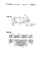
- FIG. 1 is a partially schematic side view of a passenger motor vehicle having installed therein a device for regulating the heating capacity of a heat exchanger in accordance with the present invention
- FIG. 2 is a block circuit diagram of the regulating device of FIG. 1;
- FIG. 2a is a block circuit diagram of a modified form of the regulating device of FIG. 2;
- FIG. 2b is a block diagram of a modified form of the invention for separate control of right hand and left hand passenger components of a vehicle.
- FIG. 3 is a partial cross sectional view of a round-tube heat exchanger employing an elastic material for embedding tube ends and intermediate tank in accordance with the present invention.
- a schematically illustrated passenger motor vehicle 1 includes an engine block 2, a feed conduit 3 leading from the engine block 2 to a heat exchanger 4, and a return conduit 5 leading away from the heat exchanger 4.
- An actuating member 6' in the form of an electromagnetic valve 6 is interposed in the return conduit between the heat exchanger 4 and the engine block 2.
- An internal temperature sensor 7, a heating air temperature sensor 8, and a set point generator 9 all provide output signals representing the input variables for a differential amplifier 11 (FIG. 2).
- a fan 10 is provided for acting upon the heat exchanger 4 so as to ensure uniform heating of the passenger cell of the vehicle 1 even at low speeds and/or during a standstill of the vehicle.
- the fan 10 is adapted to be automatically operated, in a conventional manner, when the speed of the vehicle falls below a predetermined value.
- the individual components of the control device are shown in the form of a block circuit diagram in FIG. 2 and, according to this figure, the heating air temperature sensor 8 is connected in front of the internal temperature sensor 7 and the combined signal of the sensors 7, 8 form an input signal for the differential amplifier 11.
- An output signal of the set point generator 9 is also fed into the differential amplifier 11 with such output signal forming the second input to the amplifier 11.
- the output signal from the differential amplifier 11 is fed into a comparator 12.
- the comparator 12 is acted upon or receives an output signal from a pulse generator 13.
- the pulse generator 13 produces a triangular or delta voltage signal of a constant frequency.
- the comparator 12 provides an output signal in the form of rectangular pulses which correspond to the triangular voltage frequency, with a pulse width of the rectangular pulses of the comparator 12 corresponding to the temperature signal of the differential amplifier 11.
- the output signal and pulses from the comparator 12 are fed to the actuating member 6 which is connected after the comparator 12.
- the electromagnet of the solenoid valve is open in the unexcited condition and is closed and opened in correspondence with the arriving rectangular pulses or output signal from the comparator 12.
- a pump 15 for pumping the heat exchange medium is inserted in the feed conduit 3 in parallel to a coolant pump 14 of the engine.
- a suitable sensing device 16 is provided for processing a speed signal from, for example, a tachometer shaft, with the sensor device being adapted to activate a relay 17 connected thereafter.
- the relay 17 is operable to activate the fan 10 if the speed of the vehicle 1 drops below a predetermined value.
- the heat exchanger 4 is constructed as a round-tube heat exchanger, with ends 18 of the tubes being supported, with the interposition of an elastic heat-resistant material 19, on respectively associated tube bottoms 20 whereby an especially smooth absorption of the switching surges of the actuating member 6 is effected.
- the heat exchange medium enters a lower water tank (not shown) and flows in the direction of the arrows indicated in FIG. 3 into an intermediate tank 21 with a particularly low heat dissipating capacity and from the intermediate tank 21 to the upper water tank 22.
- a reflux conduit 23 is provided which, as shown in FIG. 2, leads away from the intermediate tank 21 and either terminates in the return conduit 5 upstream of the actuating member 6 or, as shown in FIG. 2a, is connected through the interposition of a valve 24, controlled together with the actuating member 6, to the return conduit 5 downstream of the actuating member 6.
- a volume governor 25 may, if needed, be installed in the reflux conduit 23.
- FIG. 2b shows an embodiment of the invention characterized in that means are provided for subdividing a stream of the heat exchange medium in the heat exchanger so as to enable a separate heating of the left-hand and a right-hand passenger compartment of the vehicle, and in that a separate control means is associated with each compartment section and operates a separate actuating means.
Landscapes
- Engineering & Computer Science (AREA)
- Physics & Mathematics (AREA)
- Thermal Sciences (AREA)
- Mechanical Engineering (AREA)
- General Physics & Mathematics (AREA)
- Automation & Control Theory (AREA)
- General Engineering & Computer Science (AREA)
- Remote Sensing (AREA)
- Air-Conditioning For Vehicles (AREA)
- Air Conditioning Control Device (AREA)
Applications Claiming Priority (2)
| Application Number | Priority Date | Filing Date | Title |
|---|---|---|---|
| DE2930747A DE2930747B2 (de) | 1979-07-28 | 1979-07-28 | Einrichtung zum Regeln der Heizleistung eines Wärmetauschers |
| DE2930747 | 1979-07-28 |
Publications (1)
| Publication Number | Publication Date |
|---|---|
| US4548355A true US4548355A (en) | 1985-10-22 |
Family
ID=6077072
Family Applications (1)
| Application Number | Title | Priority Date | Filing Date |
|---|---|---|---|
| US06/172,945 Expired - Lifetime US4548355A (en) | 1979-07-28 | 1980-07-28 | Device for regulating heating capacity of a heat exchanger |
Country Status (3)
| Country | Link |
|---|---|
| US (1) | US4548355A (enExample) |
| JP (1) | JPS5625009A (enExample) |
| DE (1) | DE2930747B2 (enExample) |
Cited By (4)
| Publication number | Priority date | Publication date | Assignee | Title |
|---|---|---|---|---|
| US4928750A (en) * | 1988-10-14 | 1990-05-29 | American Standard Inc. | VaV valve with PWM hot water coil |
| US5209398A (en) * | 1992-09-02 | 1993-05-11 | Johnson Service Company | Model-based thermobalance with feedback |
| US6308702B1 (en) | 1999-05-27 | 2001-10-30 | Thomas & Betts International, Inc. | Compact high-efficiency air heater |
| US20090261176A1 (en) * | 2008-04-21 | 2009-10-22 | Gm Global Technology Operations, Inc. | Heater Coolant Flow Control for HVAC Module |
Families Citing this family (4)
| Publication number | Priority date | Publication date | Assignee | Title |
|---|---|---|---|---|
| DE3236679A1 (de) * | 1982-10-04 | 1984-04-12 | Westfälische Metall Industrie KG Hueck & Co, 4780 Lippstadt | Vorrichtung zum regeln der temperatur eines raumes, insbesondere eines innenraumes eines kraftfahrzeuges |
| IT1238090B (it) * | 1989-10-25 | 1993-07-07 | Marelli Autronica | Sistema per il controllo del riscaldamento dell'abitacolo di un autoveicolo |
| US5294050A (en) * | 1992-09-04 | 1994-03-15 | Interdynamics, Inc. | Installer climate control system |
| CN108068573A (zh) * | 2016-11-17 | 2018-05-25 | 珠海格力电器股份有限公司 | 应用于大巴车的空调系统控制方法及装置 |
Citations (6)
| Publication number | Priority date | Publication date | Assignee | Title |
|---|---|---|---|---|
| US2262496A (en) * | 1939-04-13 | 1941-11-11 | Ranco Inc | Control apparatus |
| US2489652A (en) * | 1947-01-27 | 1949-11-29 | Vapor Heating Corp | Automatic temperature control system |
| US2801802A (en) * | 1953-08-31 | 1957-08-06 | Glen C Jackson | Automobile heating system |
| US3447603A (en) * | 1967-07-03 | 1969-06-03 | Gen Electric | Means for resiliently mounting tubular members |
| US3693532A (en) * | 1970-10-26 | 1972-09-26 | Renault | Heating and ventilating system for vehicles |
| US4058255A (en) * | 1975-04-09 | 1977-11-15 | Robert Bosch Gmbh | Heater control for a motor vehicle |
Family Cites Families (2)
| Publication number | Priority date | Publication date | Assignee | Title |
|---|---|---|---|---|
| FR1577223A (enExample) * | 1967-07-21 | 1969-08-08 | ||
| DE2615476A1 (de) * | 1976-04-09 | 1977-10-20 | Bosch Gmbh Robert | Einrichtung zur regulierung der beheizung eines kraftfahrzeuginnenraums |
-
1979
- 1979-07-28 DE DE2930747A patent/DE2930747B2/de not_active Ceased
-
1980
- 1980-07-24 JP JP10061880A patent/JPS5625009A/ja active Granted
- 1980-07-28 US US06/172,945 patent/US4548355A/en not_active Expired - Lifetime
Patent Citations (6)
| Publication number | Priority date | Publication date | Assignee | Title |
|---|---|---|---|---|
| US2262496A (en) * | 1939-04-13 | 1941-11-11 | Ranco Inc | Control apparatus |
| US2489652A (en) * | 1947-01-27 | 1949-11-29 | Vapor Heating Corp | Automatic temperature control system |
| US2801802A (en) * | 1953-08-31 | 1957-08-06 | Glen C Jackson | Automobile heating system |
| US3447603A (en) * | 1967-07-03 | 1969-06-03 | Gen Electric | Means for resiliently mounting tubular members |
| US3693532A (en) * | 1970-10-26 | 1972-09-26 | Renault | Heating and ventilating system for vehicles |
| US4058255A (en) * | 1975-04-09 | 1977-11-15 | Robert Bosch Gmbh | Heater control for a motor vehicle |
Cited By (7)
| Publication number | Priority date | Publication date | Assignee | Title |
|---|---|---|---|---|
| US4928750A (en) * | 1988-10-14 | 1990-05-29 | American Standard Inc. | VaV valve with PWM hot water coil |
| US5209398A (en) * | 1992-09-02 | 1993-05-11 | Johnson Service Company | Model-based thermobalance with feedback |
| WO1994006069A1 (en) * | 1992-09-02 | 1994-03-17 | Johnson Service Company | Model-based thermobalance with feedback |
| AU659983B2 (en) * | 1992-09-02 | 1995-06-01 | Johnson Service Company | Model-based thermobalance with feedback |
| US6308702B1 (en) | 1999-05-27 | 2001-10-30 | Thomas & Betts International, Inc. | Compact high-efficiency air heater |
| US20090261176A1 (en) * | 2008-04-21 | 2009-10-22 | Gm Global Technology Operations, Inc. | Heater Coolant Flow Control for HVAC Module |
| US8740103B2 (en) * | 2008-04-21 | 2014-06-03 | GM Global Technology Operations LLC | Heater coolant flow control for HVAC module |
Also Published As
| Publication number | Publication date |
|---|---|
| JPS5625009A (en) | 1981-03-10 |
| DE2930747A1 (de) | 1981-03-12 |
| DE2930747B2 (de) | 1981-05-27 |
| JPS6248619B2 (enExample) | 1987-10-14 |
Similar Documents
| Publication | Publication Date | Title |
|---|---|---|
| US6513328B2 (en) | Internal combustion engine with cooling circuit and heating heat exchanger connected to it | |
| US6178761B1 (en) | Air conditioning circuit using a refrigerant fluid in the supercritical state, in particular for a vehicle | |
| US4185685A (en) | Waste heat recovery system and method | |
| US5794575A (en) | Coolant circuit for motor vehicles | |
| US4893603A (en) | Low pressure fuel injection system with fuel preheating for an air-compressing, injection internal combustion engine | |
| US4548355A (en) | Device for regulating heating capacity of a heat exchanger | |
| ITTO970702A1 (it) | Sistema di raffreddamento per un motore di autoveicolo. | |
| CA1139282A (en) | Motor vehicle having a passenger compartment heating device | |
| ITTO970205A1 (it) | Sistema di raffreddamento per un motore a combustione interna, parti- colarmente per autoveicoli | |
| US20010001982A1 (en) | Heating and air conditioning unit of a motor vehicle | |
| US4011988A (en) | Device for controlling the flow of cooling water in an internal combustion engine | |
| EP0777585A1 (de) | Kfz-wärmetauscher | |
| JPH02227315A (ja) | 車両用加熱システムの操作方法並びに車両用加熱システム | |
| JPS5934472A (ja) | 吸気通路壁加熱と車室内暖房の関連制御装置 | |
| US3510060A (en) | Temperature regulating device for internal combustion engines | |
| JPS591998A (ja) | 排熱回収装置の熱媒体圧力制御装置 | |
| US2500472A (en) | Control for coolants in liquid cooled motors | |
| US6105876A (en) | Heating system for vehicles | |
| US3171474A (en) | Automotive heating and cooling air conditioning system | |
| US4386734A (en) | Device for operation of a fluid circuit | |
| US3032324A (en) | Control installation for vehicle heating | |
| US2832277A (en) | Vehicle heating and ventilating apparatus | |
| US5572958A (en) | Cooling arrangement for a liquid-cooled motor vehicle internal-combustion engine | |
| JPH0466727B2 (enExample) | ||
| JPS61247856A (ja) | 蓄熱システム |
Legal Events
| Date | Code | Title | Description |
|---|---|---|---|
| STCF | Information on status: patent grant |
Free format text: PATENTED CASE |