US4530870A - Floor mat combination and detachably securable floor mat - Google Patents
Floor mat combination and detachably securable floor mat Download PDFInfo
- Publication number
- US4530870A US4530870A US06/492,590 US49259083A US4530870A US 4530870 A US4530870 A US 4530870A US 49259083 A US49259083 A US 49259083A US 4530870 A US4530870 A US 4530870A
- Authority
- US
- United States
- Prior art keywords
- mat
- recess
- floor
- thickness
- abutments
- Prior art date
- Legal status (The legal status is an assumption and is not a legal conclusion. Google has not performed a legal analysis and makes no representation as to the accuracy of the status listed.)
- Expired - Lifetime
Links
Images
Classifications
-
- A—HUMAN NECESSITIES
- A47—FURNITURE; DOMESTIC ARTICLES OR APPLIANCES; COFFEE MILLS; SPICE MILLS; SUCTION CLEANERS IN GENERAL
- A47G—HOUSEHOLD OR TABLE EQUIPMENT
- A47G27/00—Floor fabrics; Fastenings therefor
- A47G27/04—Carpet fasteners; Carpet-expanding devices ; Laying carpeting; Tools therefor
- A47G27/0406—Laying rugs or mats
- A47G27/0412—Anti-skid layers
-
- Y—GENERAL TAGGING OF NEW TECHNOLOGICAL DEVELOPMENTS; GENERAL TAGGING OF CROSS-SECTIONAL TECHNOLOGIES SPANNING OVER SEVERAL SECTIONS OF THE IPC; TECHNICAL SUBJECTS COVERED BY FORMER USPC CROSS-REFERENCE ART COLLECTIONS [XRACs] AND DIGESTS
- Y10—TECHNICAL SUBJECTS COVERED BY FORMER USPC
- Y10T—TECHNICAL SUBJECTS COVERED BY FORMER US CLASSIFICATION
- Y10T428/00—Stock material or miscellaneous articles
- Y10T428/23907—Pile or nap type surface or component
- Y10T428/23979—Particular backing structure or composition
Definitions
- the present invention relates to a floor mat combination which prevents a floor mat e.g. a rubber or similarly backed mat such as a dust control mat, from moving laterally and/or rotating on a floor, particularly a carpeted, fabric-tiled or felted floor, as the mat is walked over. It also relates to a floor mat therefor.
- a floor mat e.g. a rubber or similarly backed mat such as a dust control mat
- a mat walked over equally in two opposite directions will always move in one direction, which may be at an angle to the walking directions if the pile is not in line with the axis of the mat. Movement of the mat can also be produced on a variety of floor surfaces if during use it is walked over in one direction only, or if there is a tendency for the user to turn on the mat in one direction.
- a mat may be situated at a shop counter in such a position that customers tend to walk on to the mat from one direction and, after being served, to turn in the direction of the shop door to step off the mat. In such a location, the mat may ⁇ creep ⁇ according to the lie of the carpet pile and rotate.
- a looped fabric such as Velcro has been attached to the back of the mat and a similar or complementary fabric attached to the floor, e.g. the carpet.
- a similar or complementary fabric attached to the floor, e.g. the carpet.
- Such a mat is disclosed in GB Patent Specification No. 1518045. This provides satisfactory adhesion when the mat is new. Dust control mats, however, require regular washing and during this process the looped fabric picks up lint which is difficult to remove from the loops. They therefore become ineffective and there is a need for a more permanent solution to the problem.
- Non-woven fabric treated with a ⁇ tacky ⁇ latex adhesive has been placed between the mat and the floor, so that the fabric adheres to the flooring and the back of the mat adheres to the top of the fabric.
- the fabric is often lifted with the mat. It will then not re-adhere to the flooring since its surface has picked up fibres and dust from the flooring which spoils its adhesive quality.
- the fabric requires regular replacement and this is not an easy operation. Accordingly, there is a need for a simpler solution.
- Frames which fit around the outside edges of the mat have been used, forming a wall which restrains the movement of the mat.
- the frame has a bottom so that it forms a tray, and some frames are manufactured which actually clip the mat in place by means of the sides of the tray overlapping the mat.
- These trays are expensive to provide; they project substantially above the level of the flooring; and they collect dirt inside the frame which necessitates an extra cleaning operation. There is a need for a cheaper and less clumsy solution.
- the present invention seeks to provide an improved floor mat combination which does not ⁇ creep ⁇ in use.
- a floor mat combination comprising one or more locking elements so-called detents, detachably securable to a floor surface and a mat having its lower surface formed with one or more abutments located within its perimeter and extending generally perpendicular to the mat, the abutment(s) being arranged so that when the mat covers the locking element or elements, abutment(s) on the mat abut against or are in close proximity to complementary abutment(s) formed by the side walls of the locking element(s) on the detent or detents and thereby prevent or restrict lateral movement and/or rotation of the mat relative to the locking element(s).
- the invention also provides a floor mat for use in such a combination.
- the invention is of particular value in connection with mats whose lower surface is formed of rubber or other flexible sheet material such as PVC or other plastic materials.
- Such mats frequently have a pile or fabric upper surface, which may or may not extend to the outer edge of the mat and a rubber or like sheet backing and mats of this type are widely known for use as dust control mats.
- the lower surface of the mat is formed, e.g. by moulding, with an integral downwardly-facing recess or with a ridge or step forming a projection, said recess or projection having a side wall which is generally perpendicular to the mat surface.
- the recess on projection is substantially flat, and, if desired, more than one such recess or projection may be formed in the lower surface of the mat.
- the recesses and projections must provide a plurality of abutments generally perpendicular to the mat and facing in at least two different directions if ⁇ creep ⁇ in all directions is to be prevented. Preferably two or more of such abutments are joined together at their respective ends to form a corner.
- the abutment(s) on the mat need not be exactly perpendicular to the mat surface but may be inclined at an angle to it provided that the angle is sufficient to prevent the mat sliding up over the detent. For best results an angle of 60° or more is used and about 90° is preferred.
- the abutments on the mat should be deep enough that the mat does not readily ride up over the fixed locking element(s) on the floor but not so deep as to produce a markedly uneven upper surface when the mat is in position on the floor covering or overlying the locking element.
- each of the projections or recesses is formed in that part of the lower surface beneath the covered area, because this minimizes any visible impact of the underlying projection(s) or locking element(s).
- the abutments on the mat and locking element(s) need not be arranged to abut against one another permanently during use of the mat but can simply be arranged so that they are in close proximity and thus the recess may conform generally to the outline of the locking element and may define limits on the movement of the mat relative to the locking element(s).
- the locking elements detachably securable to the floor surface may be platens or the like which may be fixed to the floor covering, e.g. a carpet, by adhesives, tape, screws, nails, pins or in any other convenient way or may be fixed to the underlying floor either directly or through the floor covering.
- the platens or the like will have side walls forming abutment(s) complementary to the abutment(s) formed by wall means on the lower surface of the mats and may be larger or smaller than the mats or the same size as them. Preferably however they are smaller. They may be formed of wood, metal, plastics, rubber or any other relatively rigid material.
- a particularly desirable combination is a rectangular mat having a rectangular recess, so that the recess generally conforms to the outline of the platen in its lower side and a rectangular platen slightly smaller than the size of the recess.
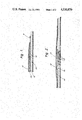
- FIGS. 1-4 are partial vertical sections of alternative embodiments of the invention.
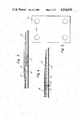
- FIG. 5 is a plan view of the embodiment shown in FIG. 4 from below.
- FIG. 1 One simple embodiment of the invention shown in FIG. 1, comprises a rectangular mat 10, e.g. of dimensions 800 ⁇ 1200 mm, including a plain rubber border 11, e.g. 20 mm in width, extending around the four edges of the mat.
- the mat has a rectangular, inward facing step or wall 12, e.g. 700 ⁇ 1100 mm in dimension, in its backing, approximately twice the thickness of the backing in depth.
- the resulting rectangular recess is centered in the backing and extends to the same distance, e.g. within 50 mm, from each of the outside edges of the mat and has an area about 80% of the area of the mat.
- the edge wall of the recess forms a 3 mm step having a face at approximately 90° to the back of the mat.
- the thickness of the backing sheet material in the recess on one side of the wall 12 is less than the thickness of the material outside the recess on the other side of the wall.
- This mat is designed to be placed on a rectangular platen 13, slightly, e.g. 20 mm, smaller in both dimensions that the recess in the back of the mat, in the specific example mentioned above being 680 mm ⁇ 1080 mm. i.e. about 76% of the area of the mat. It may be manufactured of hardboard and attached to the carpet by placing between it and the carpet 14 a piece of non-woven fabric 15 coated on both sides with ⁇ tacky ⁇ latex adhesive. The platen projects above the carpet by an amount equal to the difference between the thicknesses of the backing material on either side of the wall 12.
- Such a mat is restrained from moving in use by the reaction of the side wall of the platen against the step or wall at the edge of the recess in the mat.
- FIG. 2 Another embodiment is shown in FIG. 2.
- a recess 16 is formed around the edge of a mat 10, e.g. of dimensions 800 mm ⁇ 1200 mm, so that a rectangular projection, e.g. 500 mm ⁇ 900 mm, bounded by an outwardly facing step or wall is formed.
- the projection occupies about 46% of the mat area, so that the recess around the edge of the mat occupies about 54% of the mat surface area.
- the platen 13 takes the form of a frame, e.g. 50 mm in width, having a hole in the centre which is larger, e.g. 20 mm larger, then the rectangular projection, the frame extending close to, e.g. within 90 mm of, the edges of the mat.
- the underside of the frame has projecting stainless steel pins 17 which engage in the pile and backing of the carpet 14, holding the frame in position so that it may react against the movement of the mat.
- a mat 10 as described in connection with FIG. 2 has a frame 18 larger in external dimensions than the mat and extending to form a decorative effect around its edge.
- This frame will, however, lie flat to the floor so that there is a minimum possibility of it being tripped over.
- the mat 10 has four circular recesses 19, e.g. 150 mm in diameter, in its back--the extremities of which extend close to, e.g. within 75 mm of, the edges of the mat and are equally spaced about the centre lines of the rectangular mat.
- the platen 13 takes the form of four discs smaller in diameter than the recess of the mat, each fixed to the floor 21 with one nail 20 in the centre of each disc.
- the abutments In order that the abutments are not deformed readily by lateral forces on the mat they should not be too deep relative to the thickness of the mat in their vicinity. Usually their depth will be less than 3 times the thinnest thickness of the mat in their vicinity. Also, the abutments themselves should not be too thin, measured in a direction perpendicular to the abutments themselves. Preferably the perpendicular distance from the abutment surfaces themselves (through the material of the mat, not through the free space) to the next adjoining free space, either beyond an adjacent abutment or beyond the edge of the mat as the case may be, is at least 10 times the depth of the abutment in question.
- the surface area of the detent is preferably 50 to 85% of the surface area of the mat, but it is possible (as described above) to use a group of small locking elements, although they should not exceed about 4 in number for convenience sake.
- the thickness of the flexible sheet material of the mat around its outer edge is the same as the thickness of the mat within the recess, so that the risk of tripping is minimized.
Landscapes
- Carpets (AREA)
Applications Claiming Priority (1)
| Application Number | Priority Date | Filing Date | Title |
|---|---|---|---|
| GB8135052 | 1981-11-20 |
Publications (1)
| Publication Number | Publication Date |
|---|---|
| US4530870A true US4530870A (en) | 1985-07-23 |
Family
ID=10526042
Family Applications (1)
| Application Number | Title | Priority Date | Filing Date |
|---|---|---|---|
| US06/492,590 Expired - Lifetime US4530870A (en) | 1981-11-20 | 1983-05-09 | Floor mat combination and detachably securable floor mat |
Country Status (6)
| Country | Link |
|---|---|
| US (1) | US4530870A (de) |
| AU (1) | AU555433B2 (de) |
| BE (1) | BE895074A (de) |
| DE (2) | DE8232490U1 (de) |
| DK (1) | DK162694C (de) |
| GB (1) | GB2115693B (de) |
Cited By (5)
| Publication number | Priority date | Publication date | Assignee | Title |
|---|---|---|---|---|
| US5024868A (en) * | 1989-06-12 | 1991-06-18 | Milliken Denmark A/S | Dust control mat and method of manufacturing same |
| US5136771A (en) * | 1988-12-12 | 1992-08-11 | Milliken Denmark A/S | Method of keeping an easily removable mat or the like small carpet in place |
| US5162004A (en) * | 1989-05-19 | 1992-11-10 | Yazaki Corporation | Multi-terminal electric connector requiring low insertion and removal force |
| US10674701B2 (en) | 2015-06-19 | 2020-06-09 | Titan International, Inc. | Agricultural mat and associated systems and methods |
| US20250072642A1 (en) * | 2022-05-11 | 2025-03-06 | Kunshan Yijia Ju Textile Co., Ltd. | Detachable carpet |
Families Citing this family (3)
| Publication number | Priority date | Publication date | Assignee | Title |
|---|---|---|---|---|
| GB9002562D0 (en) * | 1990-02-06 | 1990-04-04 | Walk Off Mats Ltd | Improvements relating to floor mats |
| US5753336A (en) * | 1996-10-02 | 1998-05-19 | Stull; Thomas Emerson | Reversible underlay for rugs |
| US8309198B2 (en) | 2009-10-19 | 2012-11-13 | Product Bliss, Llc | Rugs with a mat portion |
Citations (4)
| Publication number | Priority date | Publication date | Assignee | Title |
|---|---|---|---|---|
| US2763587A (en) * | 1953-05-07 | 1956-09-18 | Masland C H & Sons | Tile floor covering |
| GB1164470A (en) * | 1965-10-18 | 1969-09-17 | Scholl Mfg Co Ltd | Improvements in and relating to Weight Supporting Mats |
| US3817015A (en) * | 1972-10-24 | 1974-06-18 | J Frangos | Convertible floor system |
| GB2066061A (en) * | 1979-12-21 | 1981-07-08 | Airomat Corp | Floor mat having anchoring elements and method of installing same |
Family Cites Families (5)
| Publication number | Priority date | Publication date | Assignee | Title |
|---|---|---|---|---|
| DE103168C (de) * | ||||
| GB192286A (en) * | 1922-02-03 | 1923-02-01 | Charles James Watts | Devices for preventing mats, rugs and the like from slipping |
| US1782293A (en) * | 1930-03-28 | 1930-11-18 | Frank M Elliott | Snap-fastener stud |
| DE1929659U (de) * | 1965-10-08 | 1965-12-23 | Claus Kolckmann | Unterlage unter teppichen, bruecken usw. zum auflegen auf einen velours-, bzw, hochnoppigen teppichboden. |
| DE1560752B1 (de) * | 1966-05-28 | 1971-04-15 | Ds Chemie Gmbh | Verfahren zum Herstellen eines florhaltigen Bodenbelages |
-
1982
- 1982-11-19 DE DE19828232490U patent/DE8232490U1/de not_active Expired
- 1982-11-19 DE DE3242829A patent/DE3242829C2/de not_active Expired - Fee Related
- 1982-11-19 GB GB08233038A patent/GB2115693B/en not_active Expired
- 1982-11-19 BE BE0/209521A patent/BE895074A/fr not_active IP Right Cessation
- 1982-11-19 DK DK516582A patent/DK162694C/da not_active IP Right Cessation
-
1983
- 1983-05-09 US US06/492,590 patent/US4530870A/en not_active Expired - Lifetime
- 1983-05-11 AU AU14481/83A patent/AU555433B2/en not_active Ceased
Patent Citations (4)
| Publication number | Priority date | Publication date | Assignee | Title |
|---|---|---|---|---|
| US2763587A (en) * | 1953-05-07 | 1956-09-18 | Masland C H & Sons | Tile floor covering |
| GB1164470A (en) * | 1965-10-18 | 1969-09-17 | Scholl Mfg Co Ltd | Improvements in and relating to Weight Supporting Mats |
| US3817015A (en) * | 1972-10-24 | 1974-06-18 | J Frangos | Convertible floor system |
| GB2066061A (en) * | 1979-12-21 | 1981-07-08 | Airomat Corp | Floor mat having anchoring elements and method of installing same |
Cited By (5)
| Publication number | Priority date | Publication date | Assignee | Title |
|---|---|---|---|---|
| US5136771A (en) * | 1988-12-12 | 1992-08-11 | Milliken Denmark A/S | Method of keeping an easily removable mat or the like small carpet in place |
| US5162004A (en) * | 1989-05-19 | 1992-11-10 | Yazaki Corporation | Multi-terminal electric connector requiring low insertion and removal force |
| US5024868A (en) * | 1989-06-12 | 1991-06-18 | Milliken Denmark A/S | Dust control mat and method of manufacturing same |
| US10674701B2 (en) | 2015-06-19 | 2020-06-09 | Titan International, Inc. | Agricultural mat and associated systems and methods |
| US20250072642A1 (en) * | 2022-05-11 | 2025-03-06 | Kunshan Yijia Ju Textile Co., Ltd. | Detachable carpet |
Also Published As
| Publication number | Publication date |
|---|---|
| DE3242829A1 (de) | 1983-06-01 |
| GB2115693B (en) | 1985-06-05 |
| DK516582A (da) | 1983-05-21 |
| DE8232490U1 (de) | 1983-03-10 |
| AU1448183A (en) | 1984-11-15 |
| GB2115693A (en) | 1983-09-14 |
| BE895074A (fr) | 1983-03-16 |
| AU555433B2 (en) | 1986-09-25 |
| DE3242829C2 (de) | 1995-04-20 |
| DK162694C (da) | 1992-04-21 |
| DK162694B (da) | 1991-12-02 |
Similar Documents
| Publication | Publication Date | Title |
|---|---|---|
| CA1328337C (en) | Mat holder | |
| US4741065A (en) | Interlocking dust control mats | |
| US3014829A (en) | Adhesived carpet blocks | |
| US4340633A (en) | Mat anchoring apparatus and method | |
| US4769895A (en) | Interlocking dust control mats | |
| CA2087594C (en) | Reinforced tile mat base and modular carpet forming system | |
| EP1014846B1 (de) | Bodenmatte | |
| US6884489B2 (en) | Universal mat with removable strips | |
| US7125595B2 (en) | Multiple-component magnetic mat | |
| US4530870A (en) | Floor mat combination and detachably securable floor mat | |
| US4415620A (en) | Mat base plate | |
| EP0011470A1 (de) | Treppenstufenbelag | |
| US3402094A (en) | Carpet tile | |
| KR20090039679A (ko) | 바닥재 시스템 | |
| WO1986001247A1 (en) | Surface covering system | |
| US4479280A (en) | Mat base plate | |
| US4762741A (en) | Non-slip floor mat combination | |
| CA1318764C (en) | Two piece dust control mat | |
| US3751327A (en) | Modular carpet system | |
| NZ204181A (en) | Preventing movement of a floor mat | |
| US3012919A (en) | Sectional fabric floor covering | |
| EP1372456B1 (de) | Fussmatte | |
| EP0373724B1 (de) | Verfahren und Gleitschutzunterlage zur Verhinderung des Wanderns von Matten oder ähnlichen kleinen Teppichen | |
| US5136771A (en) | Method of keeping an easily removable mat or the like small carpet in place | |
| JPS582297Y2 (ja) | 靴拭きマツト |
Legal Events
| Date | Code | Title | Description |
|---|---|---|---|
| AS | Assignment |
Owner name: WALK OFF MATS LIMITED, CHERRYCOURT WAY, STANBRIDGE Free format text: ASSIGNMENT OF ASSIGNORS INTEREST.;ASSIGNOR:BRAZIER, PETER C.;REEL/FRAME:004396/0300 Effective date: 19830504 |
|
| STCF | Information on status: patent grant |
Free format text: PATENTED CASE |
|
| CC | Certificate of correction | ||
| FEPP | Fee payment procedure |
Free format text: PAYOR NUMBER ASSIGNED (ORIGINAL EVENT CODE: ASPN); ENTITY STATUS OF PATENT OWNER: LARGE ENTITY |
|
| FPAY | Fee payment |
Year of fee payment: 4 |
|
| FEPP | Fee payment procedure |
Free format text: PAT HLDR NO LONGER CLAIMS SMALL ENT STAT AS SMALL BUSINESS (ORIGINAL EVENT CODE: LSM2); ENTITY STATUS OF PATENT OWNER: LARGE ENTITY |
|
| FPAY | Fee payment |
Year of fee payment: 8 |
|
| FPAY | Fee payment |
Year of fee payment: 12 |