US4525324A - Dry storage facility for irradiated nuclear reactor fuel elements - Google Patents
Dry storage facility for irradiated nuclear reactor fuel elements Download PDFInfo
- Publication number
- US4525324A US4525324A US06/451,938 US45193882A US4525324A US 4525324 A US4525324 A US 4525324A US 45193882 A US45193882 A US 45193882A US 4525324 A US4525324 A US 4525324A
- Authority
- US
- United States
- Prior art keywords
- storage
- tubes
- containers
- modules
- passageway
- Prior art date
- Legal status (The legal status is an assumption and is not a legal conclusion. Google has not performed a legal analysis and makes no representation as to the accuracy of the status listed.)
- Expired - Fee Related
Links
Images



Classifications
-
- G—PHYSICS
- G21—NUCLEAR PHYSICS; NUCLEAR ENGINEERING
- G21C—NUCLEAR REACTORS
- G21C19/00—Arrangements for treating, for handling, or for facilitating the handling of, fuel or other materials which are used within the reactor, e.g. within its pressure vessel
- G21C19/02—Details of handling arrangements
- G21C19/06—Magazines for holding fuel elements or control elements
- G21C19/07—Storage racks; Storage pools
-
- G—PHYSICS
- G21—NUCLEAR PHYSICS; NUCLEAR ENGINEERING
- G21C—NUCLEAR REACTORS
- G21C19/00—Arrangements for treating, for handling, or for facilitating the handling of, fuel or other materials which are used within the reactor, e.g. within its pressure vessel
- G21C19/02—Details of handling arrangements
- G21C19/08—Means for heating fuel elements before introduction into the core; Means for heating or cooling fuel elements after removal from the core
-
- Y—GENERAL TAGGING OF NEW TECHNOLOGICAL DEVELOPMENTS; GENERAL TAGGING OF CROSS-SECTIONAL TECHNOLOGIES SPANNING OVER SEVERAL SECTIONS OF THE IPC; TECHNICAL SUBJECTS COVERED BY FORMER USPC CROSS-REFERENCE ART COLLECTIONS [XRACs] AND DIGESTS
- Y02—TECHNOLOGIES OR APPLICATIONS FOR MITIGATION OR ADAPTATION AGAINST CLIMATE CHANGE
- Y02E—REDUCTION OF GREENHOUSE GAS [GHG] EMISSIONS, RELATED TO ENERGY GENERATION, TRANSMISSION OR DISTRIBUTION
- Y02E30/00—Energy generation of nuclear origin
- Y02E30/30—Nuclear fission reactors
Definitions
- Irradiated nuclear reactor fuel elements are kept in a basin filled with water where the radioactivity of the fuel elements falls off or decays with time. After a predetermined period of storage during which the heat generated by the radioactive decay falls off exponentially, the fuel elements are packed in transport containers and are brought to an interim storage facility. At this location, the fuel elements are stored before they are subjected to reprocessing.
- DE-OS No. 29 29 467 discloses such an intermediate storage facility which is configured as a dry storage facility whereat the fuel elements are placed into gas-tight storage containers after being removed from the transport containers. They are then placed in several storage rooms of a longitudinally extending storage building wherein they are stacked horizontally. The storage containers are cooled by natural convection. The cooling air gradually warms and moves upwardly and transfers the heat to the ambient by means of a heat exchanger.
- a dry storage facility stores radioactive materials such as irradiated nuclear reactor fuel elements that release heat produced by radioactive decay, the radioactive materials being held in gas-tight elongated storage containers.
- the dry storage facility of the invention includes an enclosure having a storage module disposed therein for accommodating the elongated storage containers, the latter being grouped into a plurality of sets of containers.
- the storage module includes means for holding the sets of containers in respective horizontal planes arranged one atop the other.
- the holding means includes ancillary holding means for holding each two mutually adjacent ones of the sets so as to cause the containers in one plane to be disposed in a direction transverse to the containers in the next adjacent plane.
- Convection cooling means is provided for cooling the storage containers.
- the enclosure of the dry storage facility can be, for example, an underground storage facility or a specially reinforced concrete building with very thick walls.
- This crosswise arrangement of the elongated storage containers causes a swirling of the rising cooling air which always flows into the intermediate spaces defined by the storage containers or storage tubes and which spaces are covered from above by the next layer of storage containers or storage tubes.
- the formation of an upward verically rising laminar flow is almost completely prevented so that the heat transferred to the available air is improved.
- the storage room or module includes a plurality of storage tubes for holding corresponding ones of the storage containers, the storage tubes being grouped into a plurality of sets of storage tubes.
- the sets are mounted in the storage module in respective horizontal planes one atop the other with the tubes of each set extending in a direction transverse to the tubes of the next adjacent set.
- the tubes of each set also extend longitudinally at an angle to the longitudinal direction of the transport passageway. This arrangement of the storage tubes permits a saving to be realized in the floor space of the storage facility.
- the width of the transport passageway between the storage modules on both sides of the storage facility and the width of the track of the crane-like transport vehicle can be configured so as to be narrower than heretofore because the loading of the storage modules is conducted at an angle with respect to both the transport passageway and the track of the bridge crane of the transport vehicle.
- the sets of storage tubes in the storage module are stacked as described above.
- every other one of the sets of storage tubes of a storage module is arranged therein so that the longitudinal axes of the tubes extend in a first direction; whereas, the tubes of the remaining sets of storage tubes of the module extend in a second direction transverse to the first direction.
- the tubes of every other one of the sets extending in the first direction are laterally displaced from the tubes of the next adjacent set of tubes extending in the first direction; and, the tubes of every other one of the sets extending in the second direction are laterally displaced from the tubes of the next adjacent set of tubes extending in the second direction.
- the rising cooling air is caused to continuously change its direction as it rises in the module through the stack of storage tubes and is thereby swirled. This swirling action increases the contact of the rising cooling air with the surfaces of the storage tubes thereby increasing the quantity of heat transferred to and conducted away by the cooling air.
- each of the storage modules can be configured as a separate block-like unit having a square base and being bounded on its four sides by vertical walls with two diagonally opposite corners of the unit defining a vertical diagonal plane bisecting the unit into two triangular halves.
- the storage modules are arranged along the side of the transport passageway so as cause the diagonal plane to extend parallel to the longitudinal direction of the passageway.
- the storage module can be loaded in crosswise fashion with elongated storage containers through both of the last-mentioned vertical walls. More specifically, the storage module can be loaded with respective sets of storage containers which lie crosswise to each other. In this way, a very effective use of space is made possible in the storage area of the enclosure wherein the storage modules are arranged.
- the transport facility in the enclosure includes a bridge crane and overhead guide means such as guide rails for guiding the bridge crane above and along the transport passageway.
- the triangular half of each of the storage modules facing the passageway can be configured so as to permit the overhead guide means to be disposed thereover.
- the other triangular half of the storage module is adapted to accommodate an exhaust conduit thereabove for conducting away the cooling medium from the storage module.
- both the transport passageway and the area taken up by the passageway and the storage modules as a group can be dimensioned so as to be narrower.
- the transport vehicle travels above half of the storage modules along the transport passageway.
- Half of the surface region of each storage module facing the passageway can be used for loading operations.
- the space requirements for the loading operation of the storage modules is therefore held to a minimum.
- the other triangular half of each storage module serves as an exhaust conduit which can be connected to a main exhaust conduit.
- FIG. 1 is a plan view of a longitudinally extending storage building of a dry storage facility taken along line I--I of FIG. 2;
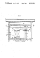
- FIG. 2 is an elevation view, partially in section, taken along the line II--II of FIG. 1;
- FIG. 3 is a section view taken through the storage building along line III--III of FIG. 1;
- FIG. 4 is a perspective view of a storage module having a portion thereof broken away to show the storage tubes for accommodating the elongated containers containing irradiated nuclear fuel elements;
- FIG. 5 is a schematic representation showing an alternate configuration of the storage tubes mounted in a storage module.
- Reference numeral 5 designates a longitudinally-extending storage building of a dry storage facility.
- the building 5 contains storage modules 7, 9, 11 and 13.
- Storage modules 7 and 9 are arranged on one longitudinal side of the building and storage modules 11 and 13 are on the other longitudinal side thereof.
- Storage module 13 is shown without any covering.
- Each of the storage modules is configured as a separate unit and has a square base area. The modules are arranged in the building 5 so that the diagonal plane defined by one pair of diagonally opposite vertical corners of each module extends in a direction parallel to the longitudinal walls 6 and 8 of the building 5.
- Supporting and guiding rails 15 and 17 are mounted in the building 5 and extend in a direction parallel to the longitudinal walls 6 and 8.
- a bridge crane 19 is mounted on the rails 15 and 17 so as to be movable therealong.
- the supporting rail 15 extends approximately over the diagonal planes of respective storage modules 7 and 9; whereas, rail 17 extends approximately over the diagonal planes of storage modules 11 and 13.
- the storage building 5 includes a base plate 21 made of concrete in which are formed four square openings 23 for receiving the storage modules 7, 9, 11 and 13, respectively.
- Each of the storage modules 7, 9, 11 and 13 is bounded by vertical concrete walls 24, 25, 26 and 27 with a concrete top covering 28.
- the supporting rails 15 and 17 upon which the bridge crane 19 runs are fixedly mounted above the storage modules 7, 9, 11 and 13.
- the bridge crane 19 is part of a transport vehicle 20 which includes a transport apparatus 29 movable in a direction transverse to the supporting rails 15 and 17 of bridge crane 19.
- the transport apparatus 29 includes a transport mast 31, a receiving apparatus 32 for receiving the storage containers 33 and a small vehicle 35.
- the receiving apparatus 32 is rotatably mounted on the mast and is provided with a pushing apparatus 37 which can move the storage containers 33 out of the receiving apparatus 32 in the direction of the longitudinal axis of the containers 33.
- the containers 33 are used to store irradiated nuclear reactor fuel rods and can be 4 to 5 meters in length and have a diameter of approximately 0.38 meters.
- a pass-through opening 41 is provided in the concrete wall 43 at the entrance of the storage building 5 through which the individual storage containers 33 can be brought into the storage building 5.
- the storage modules 7, 9, 11 and 13 are supplied with fresh cooling air via an air inlet conduit 45 of large cross section and branch conduits 47.
- the storage modules are fed by the branch conduits 47.
- the cooling air warms as it rises and is directed by exhaust conduit 48 to a main exhaust conduit 49.
- An exhaust conduit 48 is arranged atop each of the storage modules and extends over the triangular half section of each storage module facing away from the transport passageway 61.
- the other triangular half section of each module 7, 9, 11 and 13 is provided with a roof-like concrete covering 28 above which the transport vehicle 20 can run.
- Storage tubes 51 are arranged in the storage modules 7, 9, 11 and 13 so that they are stacked horizontally in sets with one set atop the other as shown in FIG. 4.
- the back end of each storage tube 51 is held by a suitable mounting arrangement embedded in concrete walls 24, 27; whereas the front ends of the storage tubes are supported in respective bores 53 in the front concrete walls 25 and 26 of each storage module 7, 9, 11 and 13, the walls 25 and 26 facing toward the transport passageway 61 extending through the storage building 5 in the longitudinal direction thereof as indicated by axis 62.
- the storage tubes 51 are also sealed about their periphery at the bores 53.
- the storage tubes 51 arranged parallel to one another in one horizontal plane extend in a direction transverse to the storage tubes lying in the next adjacent horizontal plane as shown in FIG. 4.
- the storage containers 33 holding irradiated nuclear reactor fuel elements are pushed into these storage tubes 51.
- the openings of the tubes 51 are then tightly sealed with plugs.
- the cooling air flowing through the air inlet conduit 45 is caused to flow via branch conduits 47 up through the storage modules 7, 9, 11 and 13 by the chimney effect.
- This cooling air is continuously directed away from the vertical direction as it passes upwardly through the storage modules 7, 9, 11 and 13 by the layers of storage tubes 51 arranged crosswise as shown. This leads to a swirling effect and to a good heat transfer between the storage tubes 51 and the quantity of cooling air which is available. In this way, the indirect cooling of the storage containers 33 is increased.
- the storage tubes 51 in horizontal plane c are displaced laterally from the tubes disposed in horizontal plane a so that there is a gap in horizontal plane c directly above each one of the tubes of horizontal plane a.
- the tubes of plane d are laterally displaced from the tubes of plane b in the same manner as discussed above for planes c and a. This pattern is repetitive and extends up the storage module as shown substantially in FIG. 5.
- the storage tubes of plane a always have an open gap directly above the plane c and so on.
- the upwardly flowing cooling air is continuously deflected and swirling of the cooling air is increased thereby increasing the contact of flowing air with the outer surfaces of the storage tubes; this improves the transfer of heat to the upwardly flowing cooling air from irradiated fuel elements held within storage containers in the storage tubes 51.
- An intervention room 63 extends above the rails 15 and 17 of the bridge crane.
- An auxiliary crane 65 is movably mounted within the room 63.
- the intervention room 63 is shielded by means of concrete walls.
- the transport passageway 61 between the mutually adjacent storage modules 7 and 9 on the one side and storage modules 11 and 13 on the other side can have a narrow width which must only be somewhat larger than the width of the transport mast 31.
- the storage tubes 51 of the storage modules 7, 9, 11 and 13 are loaded in the direction of their longitudinal axes which is at acute angles ⁇ 1 and ⁇ 2 to the longitudinal direction 62 of transport passageway 61 (FIG. 1).
- the storage containers 33 are passed through the concrete walls 25 and 26 of the storage modules 7, 9, 11 and 13 facing the passageway 61.
- the transport passageway 61 can be configured to have a narrow width because storage tubes 51 in the storage modules are loaded in a direction which forms an acute angle with respect to the longitudinal direction of the passageway 61. By making the passageway 61 narrower, a savings in floor space within the building 5 is realized.
Landscapes
- Physics & Mathematics (AREA)
- Engineering & Computer Science (AREA)
- Plasma & Fusion (AREA)
- General Engineering & Computer Science (AREA)
- High Energy & Nuclear Physics (AREA)
- Warehouses Or Storage Devices (AREA)
- Thermotherapy And Cooling Therapy Devices (AREA)
- Physical Or Chemical Processes And Apparatus (AREA)
Applications Claiming Priority (2)
| Application Number | Priority Date | Filing Date | Title |
|---|---|---|---|
| DE19813151310 DE3151310A1 (de) | 1981-12-24 | 1981-12-24 | Trockenlager fuer abgebrannte kernreaktorbrennelemente |
| DE3151310 | 1981-12-24 |
Publications (1)
| Publication Number | Publication Date |
|---|---|
| US4525324A true US4525324A (en) | 1985-06-25 |
Family
ID=6149685
Family Applications (1)
| Application Number | Title | Priority Date | Filing Date |
|---|---|---|---|
| US06/451,938 Expired - Fee Related US4525324A (en) | 1981-12-24 | 1982-12-21 | Dry storage facility for irradiated nuclear reactor fuel elements |
Country Status (5)
| Country | Link |
|---|---|
| US (1) | US4525324A (de) |
| EP (1) | EP0083026B1 (de) |
| JP (1) | JPS58160900A (de) |
| CA (1) | CA1190331A (de) |
| DE (2) | DE3151310A1 (de) |
Cited By (26)
| Publication number | Priority date | Publication date | Assignee | Title |
|---|---|---|---|---|
| US4701280A (en) * | 1982-06-09 | 1987-10-20 | John Canevall | Procedure for permanently storing radioactive material |
| US4776982A (en) * | 1983-11-22 | 1988-10-11 | John Canevall | Procedure for temporary storage of radioactive material |
| US4834916A (en) * | 1986-07-17 | 1989-05-30 | Commissariat A L'energie Atomique | Apparatus for the dry storage of heat-emitting radioactive materials |
| US4889681A (en) * | 1981-10-19 | 1989-12-26 | U.S. Tool & Die, Inc. | Apparatus for reducing floor and seismic loadings in underwater storage areas used in the storing of spent nuclear fuel rods |
| US5032348A (en) * | 1988-02-19 | 1991-07-16 | Transnucleaire | Stowage rack for nuclear fuel elements |
| US5152958A (en) * | 1991-01-22 | 1992-10-06 | U.S. Tool & Die, Inc. | Spent nuclear fuel storage bridge |
| US20050220257A1 (en) * | 2004-03-18 | 2005-10-06 | Singh Krishna P | Systems and methods for storing spent nuclear fuel |
| US20060251201A1 (en) * | 2005-02-11 | 2006-11-09 | Singh Krishna P | Manifold system for the ventilated storage of high level waste and a method of using the same to store high level waste in a below-grade environment |
| US20090159550A1 (en) * | 2007-12-22 | 2009-06-25 | Singh Krishna P | System and method for the ventilated storage of high level radioactive waste in a clustered arrangement |
| US20090221057A1 (en) * | 2008-02-28 | 2009-09-03 | Kennedy James C | Bio-Breeder System for Biomass Production |
| US7590213B1 (en) | 2004-03-18 | 2009-09-15 | Holtec International, Inc. | Systems and methods for storing spent nuclear fuel having protection design |
| US20100284506A1 (en) * | 2009-05-06 | 2010-11-11 | Singh Krishna P | Apparatus for storing and/or transporting high level radioactive waste, and method for manufacturing the same |
| US20110021859A1 (en) * | 2005-03-25 | 2011-01-27 | Singh Krishna P | System and method of storing and/or transferring high level radioactive waste |
| US8718220B2 (en) | 2005-02-11 | 2014-05-06 | Holtec International, Inc. | Manifold system for the ventilated storage of high level waste and a method of using the same to store high level waste in a below-grade environment |
| US8905259B2 (en) | 2010-08-12 | 2014-12-09 | Holtec International, Inc. | Ventilated system for storing high level radioactive waste |
| US9001958B2 (en) | 2010-04-21 | 2015-04-07 | Holtec International, Inc. | System and method for reclaiming energy from heat emanating from spent nuclear fuel |
| US9105365B2 (en) | 2011-10-28 | 2015-08-11 | Holtec International, Inc. | Method for controlling temperature of a portion of a radioactive waste storage system and for implementing the same |
| US9443625B2 (en) | 2005-03-25 | 2016-09-13 | Holtec International, Inc. | Method of storing high level radioactive waste |
| US9514853B2 (en) | 2010-08-12 | 2016-12-06 | Holtec International | System for storing high level radioactive waste |
| US10878973B2 (en) | 2018-09-11 | 2020-12-29 | Holtec International | Flood and wind-resistant ventilated module for spent nuclear fuel storage |
| US10892063B2 (en) | 2012-04-18 | 2021-01-12 | Holtec International | System and method of storing and/or transferring high level radioactive waste |
| US11373774B2 (en) | 2010-08-12 | 2022-06-28 | Holtec International | Ventilated transfer cask |
| US11569001B2 (en) | 2008-04-29 | 2023-01-31 | Holtec International | Autonomous self-powered system for removing thermal energy from pools of liquid heated by radioactive materials |
| US11715575B2 (en) | 2015-05-04 | 2023-08-01 | Holtec International | Nuclear materials apparatus and implementing the same |
| CN116864166A (zh) * | 2023-07-10 | 2023-10-10 | 中核能源科技有限公司 | 一种贮存格架和装料系统 |
| US11887744B2 (en) | 2011-08-12 | 2024-01-30 | Holtec International | Container for radioactive waste |
Families Citing this family (3)
| Publication number | Priority date | Publication date | Assignee | Title |
|---|---|---|---|---|
| DE3340101A1 (de) * | 1983-11-05 | 1985-05-23 | Deutsche Gesellschaft für Wiederaufarbeitung von Kernbrennstoffen mbH, 3000 Hannover | Unterirdisches zwischenlager fuer abgebrannte kernreaktorbrennelemente und fuer verglasten radioaktiven abfall |
| DE3500989A1 (de) * | 1985-01-14 | 1986-07-17 | Kraftwerk Union AG, 4330 Mülheim | Lager zur aufnahme radioaktiver abfallstoffe |
| FR2803426B1 (fr) * | 1999-12-29 | 2002-04-05 | Framatome Sa | Installation et procede d'entreposage de produits irradies et notamment d'assemblages de combustible nucleaire irradies |
Citations (14)
| Publication number | Priority date | Publication date | Assignee | Title |
|---|---|---|---|---|
| DE1053109B (de) * | 1957-01-26 | 1959-03-19 | Siemens Ag | Heterogener Kernreaktor |
| GB920256A (en) * | 1958-06-05 | 1963-03-06 | Commissariat Energie Atomique | Improvements in fuel elements for nuclear reactors |
| FR1460558A (fr) * | 1964-05-01 | 1966-03-04 | Reactor Centrum Nederland | Système de stockage pour barres fissiles ou éléments à combustible nucléaire |
| DE1614563A1 (de) * | 1964-12-02 | 1970-08-20 | Saint Gobain Techn Nouvelles | Bestrahlungsvorrichtung mit radioaktiver Quelle |
| US3935467A (en) * | 1973-11-09 | 1976-01-27 | Nuclear Engineering Co., Inc. | Repository for fissile materials |
| US4063999A (en) * | 1976-01-28 | 1977-12-20 | Westinghouse Electric Corporation | Nuclear fuel storage arrangement |
| DE2814887A1 (de) * | 1978-04-06 | 1979-10-11 | Babcock Brown Boveri Reaktor | Einrichtung zur lagerung von laenglichen kernreaktor-brennelementen in einem wassergefuellten becken |
| GB2046162A (en) * | 1979-04-04 | 1980-11-12 | Nukem Gmbh | Air circulation system for a dry store containing self-heating radiactive material |
| EP0022951A1 (de) * | 1979-07-23 | 1981-01-28 | Kraftwerk Union Aktiengesellschaft | Lager zur horizontalen Aufbewahrung von verbrauchten Kernbrennstoffstäben |
| DE2927467A1 (de) * | 1979-07-06 | 1981-02-12 | Kraftwerk Union Ag | Hilfsvorrichtung fuer die bearbeitung zweipoliger laeufer auf einer drehbank |
| DE3014252A1 (de) * | 1980-04-14 | 1981-10-15 | Kraftwerk Union AG, 4330 Mülheim | Trockenlager fuer verbrachte kernreaktor-brennelemente |
| GB2089272A (en) * | 1980-12-12 | 1982-06-23 | Noell G G Gmbh | Storage support for spent fuel elements from nuclear power stations |
| DE3101540A1 (de) * | 1981-01-20 | 1982-08-05 | Nukem Gmbh, 6450 Hanau | "vorrichtung zur lagerung waermefreisetzender radionuklidkonfigurationen" |
| US4366114A (en) * | 1979-07-20 | 1982-12-28 | Kraftwerk Union Ag | Dry storage for spent fuel assemblies |
Family Cites Families (1)
| Publication number | Priority date | Publication date | Assignee | Title |
|---|---|---|---|---|
| DE2906629C2 (de) * | 1979-02-21 | 1986-01-23 | Nukem Gmbh, 6450 Hanau | Vorrichtung zur Lagerung Wärme abgebender radioaktiver Materialien |
-
1981
- 1981-12-24 DE DE19813151310 patent/DE3151310A1/de not_active Withdrawn
-
1982
- 1982-12-14 EP EP82111614A patent/EP0083026B1/de not_active Expired
- 1982-12-14 DE DE8282111614T patent/DE3264949D1/de not_active Expired
- 1982-12-21 US US06/451,938 patent/US4525324A/en not_active Expired - Fee Related
- 1982-12-22 CA CA000418385A patent/CA1190331A/en not_active Expired
- 1982-12-23 JP JP57225129A patent/JPS58160900A/ja active Pending
Patent Citations (14)
| Publication number | Priority date | Publication date | Assignee | Title |
|---|---|---|---|---|
| DE1053109B (de) * | 1957-01-26 | 1959-03-19 | Siemens Ag | Heterogener Kernreaktor |
| GB920256A (en) * | 1958-06-05 | 1963-03-06 | Commissariat Energie Atomique | Improvements in fuel elements for nuclear reactors |
| FR1460558A (fr) * | 1964-05-01 | 1966-03-04 | Reactor Centrum Nederland | Système de stockage pour barres fissiles ou éléments à combustible nucléaire |
| DE1614563A1 (de) * | 1964-12-02 | 1970-08-20 | Saint Gobain Techn Nouvelles | Bestrahlungsvorrichtung mit radioaktiver Quelle |
| US3935467A (en) * | 1973-11-09 | 1976-01-27 | Nuclear Engineering Co., Inc. | Repository for fissile materials |
| US4063999A (en) * | 1976-01-28 | 1977-12-20 | Westinghouse Electric Corporation | Nuclear fuel storage arrangement |
| DE2814887A1 (de) * | 1978-04-06 | 1979-10-11 | Babcock Brown Boveri Reaktor | Einrichtung zur lagerung von laenglichen kernreaktor-brennelementen in einem wassergefuellten becken |
| GB2046162A (en) * | 1979-04-04 | 1980-11-12 | Nukem Gmbh | Air circulation system for a dry store containing self-heating radiactive material |
| DE2927467A1 (de) * | 1979-07-06 | 1981-02-12 | Kraftwerk Union Ag | Hilfsvorrichtung fuer die bearbeitung zweipoliger laeufer auf einer drehbank |
| US4366114A (en) * | 1979-07-20 | 1982-12-28 | Kraftwerk Union Ag | Dry storage for spent fuel assemblies |
| EP0022951A1 (de) * | 1979-07-23 | 1981-01-28 | Kraftwerk Union Aktiengesellschaft | Lager zur horizontalen Aufbewahrung von verbrauchten Kernbrennstoffstäben |
| DE3014252A1 (de) * | 1980-04-14 | 1981-10-15 | Kraftwerk Union AG, 4330 Mülheim | Trockenlager fuer verbrachte kernreaktor-brennelemente |
| GB2089272A (en) * | 1980-12-12 | 1982-06-23 | Noell G G Gmbh | Storage support for spent fuel elements from nuclear power stations |
| DE3101540A1 (de) * | 1981-01-20 | 1982-08-05 | Nukem Gmbh, 6450 Hanau | "vorrichtung zur lagerung waermefreisetzender radionuklidkonfigurationen" |
Non-Patent Citations (2)
| Title |
|---|
| "Atomkernenergie Kerntechnik", Bond 35, No. 2, 1980, pp. 111-122, Hame et . l |
| Atomkernenergie Kerntechnik , Bond 35, No. 2, 1980, pp. 111 122, Hame et al. * |
Cited By (51)
| Publication number | Priority date | Publication date | Assignee | Title |
|---|---|---|---|---|
| US4889681A (en) * | 1981-10-19 | 1989-12-26 | U.S. Tool & Die, Inc. | Apparatus for reducing floor and seismic loadings in underwater storage areas used in the storing of spent nuclear fuel rods |
| US4701280A (en) * | 1982-06-09 | 1987-10-20 | John Canevall | Procedure for permanently storing radioactive material |
| US4776982A (en) * | 1983-11-22 | 1988-10-11 | John Canevall | Procedure for temporary storage of radioactive material |
| US4834916A (en) * | 1986-07-17 | 1989-05-30 | Commissariat A L'energie Atomique | Apparatus for the dry storage of heat-emitting radioactive materials |
| US5032348A (en) * | 1988-02-19 | 1991-07-16 | Transnucleaire | Stowage rack for nuclear fuel elements |
| US5152958A (en) * | 1991-01-22 | 1992-10-06 | U.S. Tool & Die, Inc. | Spent nuclear fuel storage bridge |
| US20050220257A1 (en) * | 2004-03-18 | 2005-10-06 | Singh Krishna P | Systems and methods for storing spent nuclear fuel |
| US11342091B2 (en) | 2004-03-18 | 2022-05-24 | Holtec International | Systems and methods for storing spent nuclear fuel |
| US9916911B2 (en) | 2004-03-18 | 2018-03-13 | Holtec International, Inc. | Systems and methods for storing spent nuclear fuel |
| US20090252274A1 (en) * | 2004-03-18 | 2009-10-08 | Singh Krishna P | Systems and methods for storing spent nuclear fuel having flood protection design |
| US8625732B2 (en) | 2004-03-18 | 2014-01-07 | Holtec International, Inc. | Systems and methods for storing spent nuclear fuel |
| US8098790B2 (en) | 2004-03-18 | 2012-01-17 | Holtec International, Inc. | Systems and methods for storing spent nuclear fuel |
| US7590213B1 (en) | 2004-03-18 | 2009-09-15 | Holtec International, Inc. | Systems and methods for storing spent nuclear fuel having protection design |
| JP2008533444A (ja) * | 2005-02-11 | 2008-08-21 | ホルテック・インターナショナル・インコーポレーテッド | ハイレベル廃棄物の換気貯蔵のためのマニフォルドシステム、地下環境下でハイレベル廃棄物を貯蔵するために当該マニフォルドシステムを使用する方法 |
| US7676016B2 (en) * | 2005-02-11 | 2010-03-09 | Holtec International, Inc. | Manifold system for the ventilated storage of high level waste and a method of using the same to store high level waste in a below-grade environment |
| US9761339B2 (en) | 2005-02-11 | 2017-09-12 | Holtec International, Inc. | Manifold system for the ventilated storage of high level waste and a method of using the same to store high level waste in a below-grade environment |
| US20060251201A1 (en) * | 2005-02-11 | 2006-11-09 | Singh Krishna P | Manifold system for the ventilated storage of high level waste and a method of using the same to store high level waste in a below-grade environment |
| US11264142B2 (en) | 2005-02-11 | 2022-03-01 | Holtec International | Manifold system for the ventilated storage of high level waste and a method of using the same to store high level waste in a below-grade environment |
| WO2006086766A3 (en) * | 2005-02-11 | 2009-04-23 | Holtec International Inc | Manifold system for a ventilated storage for high level nuclear waste |
| CN101512672B (zh) * | 2005-02-11 | 2012-11-28 | 好泰克国际有限公司 | 用于通风贮存高放废物的歧管系统以及在地下环境中用该歧管系统贮存高放废物的方法 |
| US8718220B2 (en) | 2005-02-11 | 2014-05-06 | Holtec International, Inc. | Manifold system for the ventilated storage of high level waste and a method of using the same to store high level waste in a below-grade environment |
| US7933374B2 (en) | 2005-03-25 | 2011-04-26 | Holtec International, Inc. | System and method of storing and/or transferring high level radioactive waste |
| US9443625B2 (en) | 2005-03-25 | 2016-09-13 | Holtec International, Inc. | Method of storing high level radioactive waste |
| US8351562B2 (en) | 2005-03-25 | 2013-01-08 | Holtec International, Inc. | Method of storing high level waste |
| US10373722B2 (en) | 2005-03-25 | 2019-08-06 | Holtec International | Nuclear fuel storage facility with vented container lids |
| US11250963B2 (en) | 2005-03-25 | 2022-02-15 | Holtec International | Nuclear fuel storage facility |
| US20110021859A1 (en) * | 2005-03-25 | 2011-01-27 | Singh Krishna P | System and method of storing and/or transferring high level radioactive waste |
| US8660230B2 (en) * | 2007-12-22 | 2014-02-25 | Holtec International, Inc. | System and method for the ventilated storage of high level radioactive waste in a clustered arrangement |
| US20090159550A1 (en) * | 2007-12-22 | 2009-06-25 | Singh Krishna P | System and method for the ventilated storage of high level radioactive waste in a clustered arrangement |
| US9460821B2 (en) | 2007-12-22 | 2016-10-04 | Holtec International, Inc. | System and method for the ventilated storage of high level radioactive waste in a clustered arrangement |
| US20090221057A1 (en) * | 2008-02-28 | 2009-09-03 | Kennedy James C | Bio-Breeder System for Biomass Production |
| US11569001B2 (en) | 2008-04-29 | 2023-01-31 | Holtec International | Autonomous self-powered system for removing thermal energy from pools of liquid heated by radioactive materials |
| US12243662B2 (en) | 2008-04-29 | 2025-03-04 | Holtec International | Neutron absorbing apparatus |
| US8798224B2 (en) | 2009-05-06 | 2014-08-05 | Holtec International, Inc. | Apparatus for storing and/or transporting high level radioactive waste, and method for manufacturing the same |
| US20100284506A1 (en) * | 2009-05-06 | 2010-11-11 | Singh Krishna P | Apparatus for storing and/or transporting high level radioactive waste, and method for manufacturing the same |
| US10332642B2 (en) | 2009-05-06 | 2019-06-25 | Holtec International | Apparatus for storing and/or transporting high level radioactive waste, and method for manufacturing the same |
| US9001958B2 (en) | 2010-04-21 | 2015-04-07 | Holtec International, Inc. | System and method for reclaiming energy from heat emanating from spent nuclear fuel |
| US10418136B2 (en) | 2010-04-21 | 2019-09-17 | Holtec International | System and method for reclaiming energy from heat emanating from spent nuclear fuel |
| US9293229B2 (en) | 2010-08-12 | 2016-03-22 | Holtec International, Inc. | Ventilated system for storing high level radioactive waste |
| US9514853B2 (en) | 2010-08-12 | 2016-12-06 | Holtec International | System for storing high level radioactive waste |
| US11373774B2 (en) | 2010-08-12 | 2022-06-28 | Holtec International | Ventilated transfer cask |
| US8905259B2 (en) | 2010-08-12 | 2014-12-09 | Holtec International, Inc. | Ventilated system for storing high level radioactive waste |
| US10217537B2 (en) | 2010-08-12 | 2019-02-26 | Holtec International | Container for radioactive waste |
| US11887744B2 (en) | 2011-08-12 | 2024-01-30 | Holtec International | Container for radioactive waste |
| US9105365B2 (en) | 2011-10-28 | 2015-08-11 | Holtec International, Inc. | Method for controlling temperature of a portion of a radioactive waste storage system and for implementing the same |
| US10892063B2 (en) | 2012-04-18 | 2021-01-12 | Holtec International | System and method of storing and/or transferring high level radioactive waste |
| US11694817B2 (en) | 2012-04-18 | 2023-07-04 | Holtec International | System and method of storing and/or transferring high level radioactive waste |
| US11715575B2 (en) | 2015-05-04 | 2023-08-01 | Holtec International | Nuclear materials apparatus and implementing the same |
| US12100525B2 (en) | 2015-05-04 | 2024-09-24 | Holtec International | Nuclear materials apparatus and implementing the same |
| US10878973B2 (en) | 2018-09-11 | 2020-12-29 | Holtec International | Flood and wind-resistant ventilated module for spent nuclear fuel storage |
| CN116864166A (zh) * | 2023-07-10 | 2023-10-10 | 中核能源科技有限公司 | 一种贮存格架和装料系统 |
Also Published As
| Publication number | Publication date |
|---|---|
| JPS58160900A (ja) | 1983-09-24 |
| EP0083026A2 (de) | 1983-07-06 |
| DE3264949D1 (en) | 1985-08-29 |
| EP0083026A3 (en) | 1983-08-03 |
| EP0083026B1 (de) | 1985-07-24 |
| DE3151310A1 (de) | 1983-07-07 |
| CA1190331A (en) | 1985-07-09 |
Similar Documents
| Publication | Publication Date | Title |
|---|---|---|
| CA1190331A (en) | Dry storage facility for irradiated nuclear reactor fuel elements | |
| US5753925A (en) | Radioactive waste storage facility | |
| US4078968A (en) | Sealed head access area enclosure | |
| JPH0318792A (ja) | 受動形冷却装置 | |
| US4366114A (en) | Dry storage for spent fuel assemblies | |
| US4832903A (en) | Dry storage arrangements for nuclear fuel | |
| JPS5937497A (ja) | 原子炉の燃料移送設備 | |
| JP3881545B2 (ja) | キャスク貯蔵施設 | |
| SU764533A1 (ru) | Исследовательский водо-вод ной дерный реактор,бассейнового типа | |
| SE509688C2 (sv) | Metod och anordning vid bränslehantering | |
| JP5912786B2 (ja) | 放射性物質の貯蔵方法 | |
| JPS6049877B2 (ja) | 使用済長尺燃料棒の貯蔵装置 | |
| JP3075077B2 (ja) | 原子力プラント | |
| JP4014748B2 (ja) | 使用済燃料貯蔵建屋 | |
| JP2000056071A (ja) | 使用済燃料貯蔵モジュール,補助ブロック及び使用済燃料貯蔵施設 | |
| JP2004045230A (ja) | 放射性物質貯蔵施設 | |
| EP0028442A2 (de) | Anordnungen zur Lagerung von Kernbrennstoffelementen | |
| JPS6139640B2 (de) | ||
| JPS61272696A (ja) | 原子炉の燃料搬出入設備構造 | |
| JP4473770B2 (ja) | 放射性物質貯蔵施設 | |
| JPH081485Y2 (ja) | 放射性廃棄物の腐食量測定装置 | |
| JP2004108795A (ja) | 放射性物質貯蔵方法および放射性物質貯蔵施設 | |
| JP2007046994A (ja) | 使用済燃料貯蔵施設 | |
| JPH11202094A (ja) | キャニスタの貯蔵設備 | |
| JP5346893B2 (ja) | 放射性物質貯蔵施設 |
Legal Events
| Date | Code | Title | Description |
|---|---|---|---|
| AS | Assignment |
Owner name: DEUTSCHE GESELLSCHAFT FUER WIEDERAUFARBEITUNG VON Free format text: ASSIGNMENT OF ASSIGNORS INTEREST.;ASSIGNORS:SPILKER, HARRY;EINFELD, KLAUS;REEL/FRAME:004075/0523 Effective date: 19821213 |
|
| CC | Certificate of correction | ||
| FPAY | Fee payment |
Year of fee payment: 4 |
|
| LAPS | Lapse for failure to pay maintenance fees | ||
| FP | Lapsed due to failure to pay maintenance fee |
Effective date: 19930627 |
|
| STCH | Information on status: patent discontinuation |
Free format text: PATENT EXPIRED DUE TO NONPAYMENT OF MAINTENANCE FEES UNDER 37 CFR 1.362 |