US4487486A - Vertical illuminator for microscope - Google Patents
Vertical illuminator for microscope Download PDFInfo
- Publication number
- US4487486A US4487486A US06/396,407 US39640782A US4487486A US 4487486 A US4487486 A US 4487486A US 39640782 A US39640782 A US 39640782A US 4487486 A US4487486 A US 4487486A
- Authority
- US
- United States
- Prior art keywords
- illumination
- light path
- light
- field illumination
- block
- Prior art date
- Legal status (The legal status is an assumption and is not a legal conclusion. Google has not performed a legal analysis and makes no representation as to the accuracy of the status listed.)
- Expired - Fee Related
Links
Images


Classifications
-
- G—PHYSICS
- G02—OPTICS
- G02B—OPTICAL ELEMENTS, SYSTEMS OR APPARATUS
- G02B21/00—Microscopes
- G02B21/06—Means for illuminating specimens
- G02B21/08—Condensers
- G02B21/082—Condensers for incident illumination only
Definitions
- the present invention relates to a vertical illuminator for a microscope, and more particularly, to such an illuminator which permits a switching between a vertical bright field illumination and a vertical dark field illumination, by moving an optical element such as a half mirror or an annular reflecting mirror into or out of an illuminating light path.
- a vertical illuminator for a microscope is used to illuminate the surface of a specimen from an objective lens side when such a specimen is opaque (for example, when it is formed of a metallic material). It is known that such a vertical illuminator may be used to provide a bright field illumination in which a specimen is illuminated through an objective lens or a dark field illumination in which the specimen is illuminated through an annular reflecting mirror or a lens which is disposed in surrounding relationship with an objective lens.
- a vertical illuminator is known in the prior art which permits a selection between a bright and a dark field illumination.
- a half mirror which is used to provide a bright field illumination and an annular reflecting mirror which is used to provide a dark field illumination are integrally formed with a bright field illumination lens and a dark field illumination lens, respectively, so that the latter may be selectively brought into an illuminating light path to provide a desired illumination.
- One difficulty experienced with such a vertical illuminator results from a large difference in the brightness of a field being observed when the illumination is switched from the dark to the bright field illumination.
- the resulting difference is so high that the eyes of a viewer may be damaged.
- the brightness of the field being observed may be adjusted, which is inconvenient.
- any slight displacement of the annular reflecting mirror, which is used to provide the dark field illumination, from the optical axis of an objective lens prevents the illuminating light from the mirror from producing a dark field illumination.
- part of the illuminating light is allowed to impinge upon the surface of a specimen directly without being intercepted by a light shielding sleeve, allowing the light reflected by the surface to travel into the field of view, thus disadvantageously causing temporary glaring of part of the field of view. While such disadvantage represents a temporary phenomenon which occurs during the switching of the light path, the eyes of a viewer may be damaged if the switching takes place during the time the viewer is observing the specimen.
- the light diminishing member when the illumination is changed from a dark to a bright illumination, the light diminishing member is automatically inserted into the illuminating light path to decrease a difference in the brightness of the field of view which occurs as the illumination is changed, thus protecting the eyes of a viewer. No adjustment of the brightness of the field is required when changing the illumination, thus simplifying the observation. If required, the light diminishing member can be driven out of the illuminating light path, thus enabling a picture to be taken with illumination of a higher level than that used during the observation.
- the light shield member is driven into part of the illuminating light path when the illumination is changed, thus effectively preventing the incidence of extraneous light into the field of view during the changing operation and protecting the eyes of a viewer.
- the movement of the light shield member into the illuminating light path takes place automatically in interlocked relationship with an illumination changing operation, without requiring any special operation therefor.
- FIG. 1 is a longitudinal section of a light path switching assembly of a vertical illuminator for a microscope according to one embodiment of the invention
- FIG. 2 is a horizontal section of the switching assembly taken along the line II--II shown in FIG. 1;
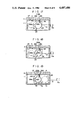
- FIGS. 3 to 5 are cross sections taken along the line III--III shown in FIG. 2, illustrating several different phases of operation of the switching assembly shown in FIG. 1;
- FIG. 6 is a longitudinal section of a light path switching assembly of a vertical illuminator for a microscope according to another embodiment of the invention.
- FIG. 7 is a horizontal section of the switching assembly taken along the line VII--VII shown in FIG. 6;
- FIGS. 8 to 10 are cross sections taken along the line VIII--VIII shown in FIG. 7, illustrating several phases of operation of the switching assembly shown in FIG. 6;
- FIG. 11 is a longitudinal section of a light path switching assembly of a vertical illuminator for a microscope according to a further embodiment of the invention.
- FIG. 12 is a horizontal section of the switching assembly shown in FIG. 11, as taken along the line XII--XII shown therein;
- FIGS. 13 and 14 are cross sections taken along the line XIII--XIII shown in FIG. 12, illustrating several phases of operation of the switching assembly shown in FIG. 11;
- FIG. 15 is a longitudinal section of a light path switching assembly of a vertical illuminator for microscope according to an additional embodiment of the invention.
- FIG. 16 is a horizontal section of the light path switching assembly of FIG. 15 as taken along the line XVI--XVI shown in FIG. 15;
- FIGS. 17 to 19 are cross sections taken along the line XVII--XVII shown in FIG. 16, illustrating several phases of operation of the switching assembly shown in FIG. 15.
- FIGS. 1 and 2 are respectively a longitudinal section and a horizontal section of a light path switching assembly of a vertical illuminator for a microscope according to a first embodiment of the invention.
- the vertical illuminator shown is adapted to be mounted between a base (not shown) of a microscope in which an objective lens is disposed and a lens barrel (also not shown) in which an eyepiece is disposed, for illuminating a specimen from the objective lens side.
- the vertical illuminator includes a body which is defined by a box-shaped frame 1 having a bottom wall which is centrally provided with attachment frame 1a for mounting the illuminator on the base of the microscope.
- the frame 1 has an open top, to which an attachment frame 2 in the form of a lid is integrally secured for allowing the lens barrel to be fixedly mounted on the illuminator.
- the attachment frame 1a is centrally formed with an opening 1b for allowing the passage of illuminating light and observation light therethrough, and a light shielding sleeve 3 is loosely fitted centrally in the opening 1b and integrally secured to the frame 1 to prevent direct impingement of a dark field illumination light onto the objective lens.
- An opening 2a is centrally formed in the upper attachment frame 2 in vertical alignment with the opening 1b to permit the passage of observation light therethrough.
- a light path switching assembly 4 is slidably disposed within the frame 1.
- the assembly 4 is defined by a rectangular block (see FIG. 3) in which a pair of juxtaposed openings 4a, 4b are formed to define the light paths for the bright and the dark field illumination, respectively.
- the front side of the block is bevelled to define an angle of 45°.
- a half mirror 8 Secured to the front end face of the block are a half mirror 8, used to provide a bright field illumination, in alignment with the opening 4a, and also an annular reflecting mirror 6, used to provide a dark field illumination, in alignment with the opening 4b.
- the annular reflecting mirror 6 has a central opening in which a light shield sleeve 11 is fitted and secured thereto in order to prevent direct impingement of dark field illumination light into the objective lens.
- Bright field illumination lenses 7 and a dark field illumination lens 5 are fitted into the rear end of the openings 4a, 4b, respectively, and are fixed therein.
- a pivot 13 is fixedly mounted on the rear surface of the block 4 at the lower, right-hand corner, as viewed in FIG. 3, and a filter carrier 12 has its one end pivotally mounted thereon.
- the filter carrier 12 is formed to have a circular extension in which a circular opening is formed to receive an N ⁇ filter 14 therein as a light diminishing member.
- the filter carrier 12 Toward the one end and out of the region of the circular opening, the filter carrier 12 fixedly carries a pin 12a which is adapted to be engaged by a pawl 17b of an expel ring 17, to be described later.
- the filter carrier 12 normally assumes a position in which its one lateral side abuts against a stop pin 15 fixedly mounted on the rear surface of the block 4 so that the N ⁇ filter 14 is located opposite to the other end of the opening 4a which defines the bright field illumination path (see FIGS. 3 and 4).
- the carrier 12 may be turned clockwise about the pivot 13 to retract the filter 14 out of the illumination path (see FIG. 5).
- a dovetail member 9 is secured to the upper end face of the block 4 so that its lengthwise direction is perpendicular to the length of the openings 4a, 4b, and is slidably fitted into a dovetail groove 2b formed in the lower surface of the attachment frame 2.
- a rod-shaped light path switching member 10 Secured to the right-hand side, or the lower surface as viewed in FIG. 2, of the block 4 is one end of a rod-shaped light path switching member 10, the free end of which extends through an opening formed in the frame 1 to the outside thereof, with a knob 10a fixedly mounted thereon.
- reference characters 20a, 20b represent cut set screws which are fixed in the frame 1 for abutment against the lateral sides of the block 4 to limit its extent of movement in a manner such that in each abutting position of the block, the opening 1b is aligned with either the half mirror 8 or the annular reflecting mirror 6, respectively. Accordingly, when the knob 10a is pushed toward the sidewall of the frame 1, the guiding action provided by the cooperation between the dovetail member 9 and the dovetail groove 2a causes a sliding movement of the block 4 until it abuts against the cut screw 20a (see (FIG. 3), whereupon it comes to a rest and establishes a condition for dark field illumination.
- Such position of the block 4 will be hereafter referred to as a position for dark field illumination. Subsequently when the knob 10a is pulled away from the frame 1, the block 4 similarly slides unti it bears against the cut screw 20b (see FIG. 4) where it comes to a rest and establishes a condition for bright field illumination. This position of the block 4 will be hereafter referred to as a position for bright field illumination.
- An illumination lens frame 16 has its one end fixedly mounted in the central region of the rearwall of the frame 1, or the right-hand sidewall as viewed in FIGS. 1 and 2, and extend through the rear wall.
- the lens frame 16 is disposed so that its central axis aligns with the axis of either opening 4a or 4b when the block assumes a position for bright or dark field illumination, respectively.
- Adjacent to the one end of the lens frame 16, an expel ring 17 in the form of a short hollow cylinder is rotatably disposed therein and is locked against withdrawal by a wire ring 16a.
- the expel ring 17 includes a pawl 17b which projects into the frame 1 for causing a movement of the pin 12a to retract the N ⁇ filter 14 out of the illumination light path.
- the expel ring 17 Adjacent to its rear end, the expel ring 17 fixedly carries an operating pin 17a on its sidewall, which extends through a diametrical slot formed in the lens frame 16 to the outside thereof.
- a coiled tension spring 18 has its one end anchored to a pin 19 which is fixedly mounted on the frame 1 and its other end engaged with the pawl 17b, whereby the expel ring 17 is urged to rotate clockwise, as viewed from the direction of an arrow A shown in FIG. 1.
- the resulting rotation of the expel ring 17 causes it to assume a normal position in which the operating pin 17a abuts against one end face of the slot.
- the pawl 17b assumes its lowermost position where in the condition for bright field illumination, it bears against the pin 12a on the filter carrier 12 which has its one lateral side abutting against the stop pin 15 (see FIG. 4). Accordingly, if the pin 17a is operated against the resilience of the spring 18 under this condition, the expel ring 17 rotates to cause the pawl 17b to expel the pin 12a, thus causing the filter carrier 12 to rotate about the pivot 13 to expel the N ⁇ filter 14 out of the illumination light path (see FIG. 5).
- an illumination lens is disposed in the other end of the lens frame 16, which is connected to a lamp housing including an illumination lamp therein.
- FIG. 3 shows a condition for dark field illumination achieved by pushing the knob 10a toward the frame 1.
- the block 4 bears against the cut screw 20a and the opening 4b is aligned with the lens frame 16, and the annular reflecting mirror 6 is aligned with the opening 1b (see FIG. 2). Therefore, light emitted by the illumination lamp passes through the illumination lens 5 and falls onto the annular mirror 6 where only marginal light, exclusive of central light, is reflected by the mirror 6 to pass through the marginal region of the opening 1b, outside the light shield sleeve 3, for illuminating the surface of a specimen. In this manner, a dark field illumination is achieved.
- the knob 10a is pulled away from the frame 1 to bring the block 4 into abutment against the cut screw 20b where a position for bright field illumination is reached, as shown in FIG. 4, the lens frame 16 is now aligned with the opening 4a and the half mirror 8 is aligned with the opening 1b, thus establishing a condition for bright field illumination.
- the filter carrier 12 moves together with the block 4 while maintaining its abutment against the stop pin 15, whereby the filter 14 is inserted into the illuminating light path.
- the N ⁇ filter 14 When an illumination of an increased level is required under the condition of bright field illumination for purpose of taking a picture, the N ⁇ filter 14 may be manually expelled out of the illumination light path. To this end, the operating pin 17a may be turned against the resilience of the spring 18. This causes the expel ring 17 to rotate counter-clockwise, whereby the pawl 17b drives the pin 12a to rotate the filter carrier 12 clockwise about the pivot 13 to expel the N ⁇ filter 14 out of the illumination light path, as shown in FIG. 5.
- the expel ring 17 rotates in the opposite direction under the resilience of the spring 18 until its normal position is resumed, but the filter carrier 12 remains in a position in which its lateral side remote from the pin 12a bears against the bottom of the frame 1 by gravity, thus maintaining the filter 14 out of the illumination light path.
- the purpose of allowing only the expel ring 17 to be returned to its normal position is to avoid the inconvenience that the pin 12a may remain entangled with the pawl 17b when changing the illumination from the bright to the dark field illumination or that the pawl 17b may inadvertently engage the pin 12a to expel the filter carrier 12 out of the illumination light path when changing from the dark to the bright field illumination, which migh occur if the pawl 17b is left in a position engageable with the pin 12a.
- an illumination of a sufficient brightness is available for purpose of taking a picture, by expelling the filter 14 out of the illumination light path, as required.
- the knob 10a To return to the condition for dark field illumination from the condition for bright field illumination in which the filter 14 is expelled out of the illumination light path, it is only necessary that the knob 10a be pushed toward the frame 1. As the knob 10a is pushed, the filter carrier 12 comes into abutment against the inner wall of the frame 1 to be urged thereby to rotate counter-clockwise about the pivot 13, inasmuch as the location of abutment is disposed above the pivot 13. In the condition for dark field illumination which is achieved by fully pushing the knob 10a toward the frame (see FIG. 2), the filter carrier 12 automatically returns to its position where its one lateral side bears against the stop pin 15 and where it is aligned with the opening 4a. When returning from the condition for bright field illumination shown in FIG. 4 where the filter 14 remains on the illumination light path to the condition for dark field illumination shown in FIG. 3, the filter carrier 12 moves together with the block 4 while maintaining its abutment against the stop pin 15, and the N ⁇ filter 14 also moves out of the illumination light path.
- FIGS. 6 and 7 are a longitudinal section and a horizontal section of a light path switching assembly of a vertical illuminator for microscope according to another embodiment of the invention.
- the vertical illuminator shown achieves the similar functioning and effect as the previous embodiment, by mounting a filter carrier 12A in a rotatable manner on the frame 1, rather than rotatably mounting the filter carrier 12 on the block 4 as in the vertical illuminator of FIGS. 1 to 5.
- the filter carrier 12A of this embodiment is formed of a magnetic material, and has its one end pivotally mounted on a pivot 13a (see FIG. 8) which is fixedly mounted on the rear wall of the frame 1.
- the location of the pivot 13a is chosen to be on the lower, left-hand side, as viewed in FIG.
- a stop pin 15A is fixedly mounted on the rear wall of the frame 1 at its left-hand, lower corner for abutment against one lateral sides of the filter carrier 12A to limit the angular movement thereof when the filter carrier 12A is expelled out of the illumination light path.
- a pin 12Aa is fixedly mounted on the rear side of the filter carrier 12A centrally lengthwise and toward the other side which is remote from the side adjacent which the pin 15A is located, for engagement with a pawl 17b of an expel ring 17.
- An elongate permanent magnet 21 is fixedly mounted centrally on the rear surface of the block 4 and projects rearwardly.
- the magnet 21 bears against the other side of the filter carrier 12A, which comprises a magnetic material, to hold it by attraction whenever the block 4 has moved to its position for dark field illumination (see FIG. 8).
- FIG. 8 shows the block 4 in a position for dark field illumination, which is achieved by pushing the knob 10a toward the frame 1.
- the opening 4b is located opposite to the illumination lens frame 16, the annular reflecting mirror 6 is aligned with the opening 1b (see FIG. 7), and the filter carrier 12A is driven by the permanent magnet 21 to move out of the illumination light path. Accordingly, light emitted by the illumination lamp passes through the illumination lens 5 and is reflected by the annular mirror 6 to provide a dark field illumination of the surface of a specimen.
- the opening 4a is located opposite to the lens frame 16
- the half mirror 8 is aligned with the opening 1b and the filter carrier 12A moves clockwise about the pivot 13A while being held attracted to the magnet 21, thus bringing the N ⁇ filter 14 into the illumination light path. Accordingly, the light emitted by the illumination lamp is diminished in intensity by the filter 14 to reach the half mirror 8, which reflects it to provide a bright field illumination of the surface of a specimen.
- the operating pin 17a may be operated to cause a clockwise rotation of the expel ring 17 as indicated in phantom line in FIG. 10.
- This causes the pawl 17b to drive the pin 12Aa to rotate the filter carrier 12A counter-clockwise about the pivot 13A against the attraction exerted by the magnet 21 until its lateral side bears against the stop pin 15A where it rests stationary and located out of the light path.
- the light emitted by the illumination lamp reaches the half mirror 8 without being attenuated by the filter 14 to provide a bright field illumination of the surface of a specimen at a higher level.
- the pin 17a is released, the ring 17 automatically returns to its normal position under the resilience of a spring 18.
- the knob 10a may be pushed toward the frame 1. This causes the block 4 to move until the opening 4b is aligned with the lens frame 16, the annular mirror 6 is aligned with the opening 1b and the magnet 21 bears against the lateral side of the filter carrier 12A, thus achieving a condition for dark field illumination.
- the light diminishing member comprises an N ⁇ filter, but any other member such as diffuser plate may be used instead.
- such mechanism may comprise other means, for example, a plunger solenoid which is provided with a return spring.
- the filter carrier in a rotatable manner so as to be moved into or out of the illumination light path, it may be slidably disposed on a guide rail which is mounted on the body frame to provide a similar functioning.
- the entire filter carrier is formed of a magnetic material, but only that portion of the carrier which is adapted to engage the permanent magnet may be formed of a magnetic material.
- FIGS. 11 and 12 are a longitudinal section and a horizontal section of a light path switching assembly of a vertical illuminator for microscope according to a further embodiment of the invention.
- a light shield member which is designed to avoid an inconvenience that the illuminating light which is totally reflected by the annular mirror 6 temporarily passes through the objective lens to impinge upon the surface of a specimen directly, whereby part of the field of view glares to a very high level to thereby cause a damage of the eyes of a viewer.
- the shield member operates to intercept such harmful light. As shown in FIG.
- a sickle-shaped light shield member 23 has its one end pivotally mounted on a pivot 24 which is fixedly mounted on the rear side of the block 4 so that it advances partly into the illumination light path to intercept harmful light.
- the light shield member 23 includes a sickle-shaped shield 23a which extends downwardly and to the right, as viewed in FIG. 13, and a short projection 23b which extends vertically upward. Since the pivot 24 is fixedly mounted on the rear side of the block 4 at a point adjacent to the top of the opening 4b and slightly offset to the left thereof, the shield member is capable of effectively intercepting the right-hand peripheral region of the illumination light path.
- An expel member 26 is fixedly mounted on the attachment frame 2 for engagement with the vertical projection 23b to control the angular limit to which the light shield member 23 can be turned clockwise.
- a stop pin 25 is fixedly mounted on the rear side of the block 4 toward the left-hand, upper corner thereof for abutment against the lateral side of the projection 23b to limit the angle to which the light shield member 23 can be turned counter-clockwise.
- FIG. 13 shows the light path switching block 4 assuming its position for dark field illumination, which is attained by pushing the knob 10a toward the frame 1.
- the projection 223b bears against the expel member 26, whereby the light shield member 23 assumes its angular position about the pivot 24 which is most advanced counter-clockwise, and the shield 23a is retracted out of the illumination light path.
- the light emitted by the illumination lamp provides a dark field illumination of the surface of a specimen, without being in any way intercepted by the light shield member 23.
- the block 4 moves to cause the center of the annular mirror 6 to be displaced from the principal optical axis of the objective lens, whereby the illuminating light which is totally reflected by the right-hand edge, as viewed in FIG. 13, of the reflecting mirror 6 would be partly effective to provide a direct illumination of the surface of a specimen through the objective lens.
- the projection 23b is no longer constrained by the expel member 26, whereby the light shield member 23 slightly turns clockwise about the pivot 24 by gravity, and comes to a stop by abutment against the stop pin 25 where the sickle-shaped shield 23a is advanced into the illumination light path.
- the illuminating light which would otherwise impinge upon the right-hand edge of the annular mirror 6 is intercepted, preventing the likelihood that the totally reflected light from the mirror 6 directly illuminates the surface of the specimen. In this manner, the likelihood is avoided that part of the field of view assumes a very high brightness to cause a damage to the eyes of a viewer.
- the light shield member 23 is located opposite to the opening 4b. Subsequently, when the knob 10a is pushed again toward the frame 1, the projection 13b abuts against the expel member 26 immediately before a condition for dark field illumination is established, thus causing the light shield member 23 to rotate counter-clockwise about the pivot 24 to be moved out of the illumination light path. Thus, the likelihood of the totally reflected light from the annular mirror 6 directly illuminating the surface of specimen to cause a damage to the eyes of a viewer is again avoided, as when changing from the dark to the bright field illumination.
- FIGS. 15 and 16 are a longitudinal section and a horizontal section of a light path switching assembly of a vertical illuminator for microscope according to an additional embodiment of the invention.
- This vertical illuminator achieves the similar functioning and effect as that achieved by the vertical illuminator shown in FIGS. 11 to 14, by rockably mounting a light shield member 25A on the frame 1, rather than providing the light shield member 23 on the block 4 in a rockable manner as in FIGS. 11 to 14.
- the light shield member 23A is rockably mounted on a pivot 24A which is fixedly mounted on the inside of the rear wall of the frame 1 (see FIG. 17).
- the member 23A includes a shield 23Aa and a projection 23Ab, and also includes a second projection 23Ac which extends a short distance in the opposite direction from the projection 23Ab.
- the projection 23Ab will be hereafter referred to as a first projection to make a distinction from the second projection 23Ac.
- the location of the pivot 24A is chosen to be adjacent to the top of the illumination lens frame 16 and slightly displaced to the right therefrom, as viewed in FIG. 17, so that as the light shield member 23A rocks about the pivot 24A, it can be moved into or out of the illumination light path which is defined by the lens frame 16. As the light shield member 23A moves angularly to overlap the left-hand edge of the illumination light path, as viewed in FIG.
- the free end of the shield 23Aa engages a tab 29 formed on the bottom of the frame 1 to prevent a further angular movement of the light shield member into the illumination light path.
- An expel member 27 and an expel pin 28 are fixedly mounted on the rear side of the block 4 for retracting the light shield member 23A out of the illumination light path.
- the expel member 27 is fixedly mounted on the rear side of the block 4 adjacent to the upper, left-hand corner, as viewed in FIG. 17, so as to abut against the first projection 23Ab from the left.
- the expel pin 28 is fixedly mounted on the rear side of the block 4 adjacent to the upper, right-hand corner, as viewed in FIG. 17, so as to be capable of abutting against the second projection 23Ac from the right.
- FIG. 17 shows a position of the block 4 for dark field illumination, which is attained by pushing the knob 10a toward the frame 1.
- the expel pin 28 abuts against the second projection 23Ac from the right thereof, whereby the light shield member 23A rotates clockwise about the pivot 24A to be expelled out of the illumination light path. Accordingly, the light emitted by the illumination lamp provides a dark field illumination of the surface of the specimen without being intercepted in any way by the light shield member 23A.
- the movement of the block 4 causes the expel pin 28 to be disengaged from the second projection 23Ac, whereby the light shield member 23A rotates about the pivot 24A by gravity, allowing the shield 23Aa to engage the tab 29 where it comes to a stop, partly advanced into the illumination light path.
- the light shield member 23A intercepts the illuminating light which is totally reflected by the annular mirror 6 and which tends to be incident on the objective lens. This avoids the likelihood that part of the field of view assumes a very high brightness level to cause a damage to the eyes of a viewer.
- the expel member 27 abuts against the first projection 23Ab from the left immediately before a position for bright field illumination is reached, causing the light shield member 23A to rotate clockwise about the pivot 24A to expel the member 23A out of the illumination light path, as indicated in FIG. 19. Accordingly, the illuminating light provides a bright field illumination of the surface of a specimen without being intercepted by the light shield member 23A.
- the condition for bright field illumination is established.
- the expel member 27 moves away from the first projection 23Ab after a slight stroke of the knob, whereby the light shield member 23A turns counter-clockwise about the pivot 24A by gravity, advancing into the illumination light path and engaging the tab 29 whereupon it comes to a stop.
- the expel pin 28 abuts against the second projection 23Ac from the right, causing the light shield member 23A to rotate clockwise about the pivot 24, thus expelling it out of the illumination light path to establish a condition for dark field illumination.
- the light which is totally reflected by the annular mirror 6 and impinging upon the objective lens is effectively intercepted by the light shield member 23A.
- the illuminating light provides a dark field illumination of the surface of a specimen without being in any way intercepted by the light shield member 23A.
Landscapes
- Physics & Mathematics (AREA)
- Chemical & Material Sciences (AREA)
- Analytical Chemistry (AREA)
- General Physics & Mathematics (AREA)
- Optics & Photonics (AREA)
- Microscoopes, Condenser (AREA)
Applications Claiming Priority (8)
| Application Number | Priority Date | Filing Date | Title |
|---|---|---|---|
| JP11798581A JPS5818603A (ja) | 1981-07-28 | 1981-07-28 | 落射明暗視野照明装置 |
| JP56-117985 | 1981-07-28 | ||
| JP56-117984 | 1981-07-28 | ||
| JP11798481A JPS5818613A (ja) | 1981-07-28 | 1981-07-28 | 落射明暗視野照明装置 |
| JP16242781A JPS5863913A (ja) | 1981-10-12 | 1981-10-12 | 落射明暗視野照明装置 |
| JP16242681A JPS5863912A (ja) | 1981-10-12 | 1981-10-12 | 落射明暗視野照明装置 |
| JP56-162426 | 1981-10-12 | ||
| JP56-162427 | 1981-10-12 |
Publications (1)
| Publication Number | Publication Date |
|---|---|
| US4487486A true US4487486A (en) | 1984-12-11 |
Family
ID=27470481
Family Applications (1)
| Application Number | Title | Priority Date | Filing Date |
|---|---|---|---|
| US06/396,407 Expired - Fee Related US4487486A (en) | 1981-07-28 | 1982-07-08 | Vertical illuminator for microscope |
Country Status (2)
| Country | Link |
|---|---|
| US (1) | US4487486A (ja) |
| DE (1) | DE3228041C2 (ja) |
Cited By (9)
| Publication number | Priority date | Publication date | Assignee | Title |
|---|---|---|---|---|
| GB2182170A (en) * | 1985-10-28 | 1987-05-07 | Zeiss Stiftung | Microscope with a reflecter and supplementary sliders |
| GB2188447A (en) * | 1986-03-29 | 1987-09-30 | Leitz Ernst Gmbh | Optical insert module for an optical instrument |
| US5325231A (en) * | 1991-03-22 | 1994-06-28 | Olympus Optical Co., Ltd. | Microscope illuminating apparatus |
| US6222671B1 (en) * | 1996-11-12 | 2001-04-24 | Nikon Corporation | Optical element switching device |
| US6373626B1 (en) | 1999-11-25 | 2002-04-16 | Mitutoyo Corporation | Bright and dark field switching device and microscope |
| US6600598B1 (en) | 1998-09-02 | 2003-07-29 | W. Barry Piekos | Method and apparatus for producing diffracted-light contrast enhancement in microscopes |
| US20040120030A1 (en) * | 2002-12-23 | 2004-06-24 | Leica Microsystems Inc., Eai | Multiple phase contrast annulus slider |
| US20100309573A1 (en) * | 2007-11-29 | 2010-12-09 | Carl Zeiss Microimaging Gmbh | Optics Changer |
| US11385452B2 (en) * | 2015-03-13 | 2022-07-12 | Genea Ip Holdings Pty Limited | Method and apparatus for microscopy |
Families Citing this family (2)
| Publication number | Priority date | Publication date | Assignee | Title |
|---|---|---|---|---|
| DE3442218A1 (de) * | 1984-11-19 | 1986-05-28 | Fa. Carl Zeiss, 7920 Heidenheim | Auflichtbeleuchtungsapparat fuer mikroskope |
| DE3535749A1 (de) * | 1985-04-12 | 1986-10-16 | Fa. Carl Zeiss, 7920 Heidenheim | Einrichtung zur helligkeitsregelung in mikroskopen |
Citations (8)
| Publication number | Priority date | Publication date | Assignee | Title |
|---|---|---|---|---|
| US1157257A (en) * | 1914-08-31 | 1915-10-19 | Zeiss Carl Fa | Microscope-condenser. |
| DE569884C (de) * | 1931-06-30 | 1933-02-09 | Emil Busch A G Optische Ind | Vorrichtung zur Beleuchtung mikroskopischer Objekte |
| US2103230A (en) * | 1937-06-30 | 1937-12-28 | Bausch & Lomb | Microscope illuminator |
| US2766655A (en) * | 1952-11-03 | 1956-10-16 | Leitz Ernst Gmbh | Phase contrast microscope |
| JPS5240149A (en) * | 1975-09-20 | 1977-03-28 | Leitz Ernst Gmbh | Downward illumination device for bright field and dark field illumination |
| JPS54103362A (en) * | 1978-01-31 | 1979-08-14 | Matsushita Electric Ind Co Ltd | Optical observation apparatus |
| US4329014A (en) * | 1979-06-15 | 1982-05-11 | Ernst Leitz Wetzlar Gmbh | Incident light illumination instrument for selective light and dark field illumination |
| US4368947A (en) * | 1979-11-13 | 1983-01-18 | Olympus Optical Co., Ltd. | Turret condenser for microscopes |
Family Cites Families (2)
| Publication number | Priority date | Publication date | Assignee | Title |
|---|---|---|---|---|
| DE282925C (ja) * | 1915-03-26 | |||
| DE6922326U (de) * | 1969-05-31 | 1969-11-20 | Leitz Ernst Gmbh | Analysator fuer polarisationsmikroskope |
-
1982
- 1982-07-08 US US06/396,407 patent/US4487486A/en not_active Expired - Fee Related
- 1982-07-27 DE DE3228041A patent/DE3228041C2/de not_active Expired
Patent Citations (8)
| Publication number | Priority date | Publication date | Assignee | Title |
|---|---|---|---|---|
| US1157257A (en) * | 1914-08-31 | 1915-10-19 | Zeiss Carl Fa | Microscope-condenser. |
| DE569884C (de) * | 1931-06-30 | 1933-02-09 | Emil Busch A G Optische Ind | Vorrichtung zur Beleuchtung mikroskopischer Objekte |
| US2103230A (en) * | 1937-06-30 | 1937-12-28 | Bausch & Lomb | Microscope illuminator |
| US2766655A (en) * | 1952-11-03 | 1956-10-16 | Leitz Ernst Gmbh | Phase contrast microscope |
| JPS5240149A (en) * | 1975-09-20 | 1977-03-28 | Leitz Ernst Gmbh | Downward illumination device for bright field and dark field illumination |
| JPS54103362A (en) * | 1978-01-31 | 1979-08-14 | Matsushita Electric Ind Co Ltd | Optical observation apparatus |
| US4329014A (en) * | 1979-06-15 | 1982-05-11 | Ernst Leitz Wetzlar Gmbh | Incident light illumination instrument for selective light and dark field illumination |
| US4368947A (en) * | 1979-11-13 | 1983-01-18 | Olympus Optical Co., Ltd. | Turret condenser for microscopes |
Cited By (15)
| Publication number | Priority date | Publication date | Assignee | Title |
|---|---|---|---|---|
| GB2182170A (en) * | 1985-10-28 | 1987-05-07 | Zeiss Stiftung | Microscope with a reflecter and supplementary sliders |
| GB2182170B (en) * | 1985-10-28 | 1989-09-20 | Zeiss Stiftung | Microscope with a reflector slider |
| GB2188447A (en) * | 1986-03-29 | 1987-09-30 | Leitz Ernst Gmbh | Optical insert module for an optical instrument |
| DE3610692A1 (de) * | 1986-03-29 | 1987-10-01 | Leitz Ernst Gmbh | Modulare einrichtung |
| US4753525A (en) * | 1986-03-29 | 1988-06-28 | Ernst Leitz Wetzlar Gmbh | Modular device |
| GB2188447B (en) * | 1986-03-29 | 1989-11-15 | Leitz Ernst Gmbh | Optical insert module for an optical instrument |
| US5325231A (en) * | 1991-03-22 | 1994-06-28 | Olympus Optical Co., Ltd. | Microscope illuminating apparatus |
| US6222671B1 (en) * | 1996-11-12 | 2001-04-24 | Nikon Corporation | Optical element switching device |
| US6600598B1 (en) | 1998-09-02 | 2003-07-29 | W. Barry Piekos | Method and apparatus for producing diffracted-light contrast enhancement in microscopes |
| US6373626B1 (en) | 1999-11-25 | 2002-04-16 | Mitutoyo Corporation | Bright and dark field switching device and microscope |
| US20040120030A1 (en) * | 2002-12-23 | 2004-06-24 | Leica Microsystems Inc., Eai | Multiple phase contrast annulus slider |
| US6804050B2 (en) * | 2002-12-23 | 2004-10-12 | Leica Microsystems Inc. | Multiple phase contrast annulus slider |
| US20100309573A1 (en) * | 2007-11-29 | 2010-12-09 | Carl Zeiss Microimaging Gmbh | Optics Changer |
| US8194312B2 (en) * | 2007-11-29 | 2012-06-05 | Carl Zeiss Microimaging Gmbh | Optics changer |
| US11385452B2 (en) * | 2015-03-13 | 2022-07-12 | Genea Ip Holdings Pty Limited | Method and apparatus for microscopy |
Also Published As
| Publication number | Publication date |
|---|---|
| DE3228041C2 (de) | 1986-02-27 |
| DE3228041C3 (ja) | 1989-02-02 |
| DE3228041A1 (de) | 1983-02-17 |
Similar Documents
| Publication | Publication Date | Title |
|---|---|---|
| US4487486A (en) | Vertical illuminator for microscope | |
| DE3639751C2 (ja) | ||
| JPH0629926B2 (ja) | パララツクス補正装置 | |
| US4265526A (en) | Camera provided with a data recording device | |
| GB1527823A (en) | Rear screen projector with remote projection capability | |
| JP2682656B2 (ja) | 写真カメラ | |
| USRE26763E (en) | Cameras with built-in plash assemblies | |
| JPS62121428A (ja) | 一眼レフレツクスカメラ | |
| US3623804A (en) | Microfilm projector apparatus | |
| CA2031514C (en) | Photographic attachment and shutter device for a binocular microscope | |
| US4331402A (en) | Single-lens reflex camera | |
| JPH028283B2 (ja) | ||
| US3529524A (en) | Camera capable of automatic switching between built-in exposure controls for daylight and flash photographing | |
| US5565942A (en) | Camera with built-in flash | |
| US3334544A (en) | Slide projector with slide actuated shutter | |
| US5276473A (en) | Manually set bounce flash with focus shift | |
| US4193676A (en) | Data photographic device for camera | |
| US4179199A (en) | Combination motion picture camera and viewing apparatus | |
| US5305037A (en) | Strobe device of camera | |
| US5678100A (en) | Douser mounting structure for a photographic camera having a panoramic photographing function | |
| US2518671A (en) | Focusing mechanism for lens mounts | |
| US4109260A (en) | Superimposing device for use in a data-recording camera | |
| GB2207828A (en) | Automatic focusing | |
| GB2171528A (en) | Conversion to half frame camera | |
| JP3687142B2 (ja) | 閃光器 |
Legal Events
| Date | Code | Title | Description |
|---|---|---|---|
| AS | Assignment |
Owner name: OLYMPUS OPTICAL COMPANY LTD 43-2 2-CHOME,HATAGAYA, Free format text: ASSIGNMENT OF ASSIGNORS INTEREST.;ASSIGNOR:HAYASAKA, TOSHIMI;REEL/FRAME:004021/0302 Effective date: 19820630 Owner name: OLYMPUS OPTICAL COMPANY LTD, JAPAN Free format text: ASSIGNMENT OF ASSIGNORS INTEREST;ASSIGNOR:HAYASAKA, TOSHIMI;REEL/FRAME:004021/0302 Effective date: 19820630 |
|
| FPAY | Fee payment |
Year of fee payment: 4 |
|
| FEPP | Fee payment procedure |
Free format text: PAYOR NUMBER ASSIGNED (ORIGINAL EVENT CODE: ASPN); ENTITY STATUS OF PATENT OWNER: LARGE ENTITY |
|
| FPAY | Fee payment |
Year of fee payment: 8 |
|
| FEPP | Fee payment procedure |
Free format text: PAYER NUMBER DE-ASSIGNED (ORIGINAL EVENT CODE: RMPN); ENTITY STATUS OF PATENT OWNER: LARGE ENTITY Free format text: PAYOR NUMBER ASSIGNED (ORIGINAL EVENT CODE: ASPN); ENTITY STATUS OF PATENT OWNER: LARGE ENTITY |
|
| REMI | Maintenance fee reminder mailed | ||
| LAPS | Lapse for failure to pay maintenance fees | ||
| FP | Lapsed due to failure to pay maintenance fee |
Effective date: 19961211 |
|
| STCH | Information on status: patent discontinuation |
Free format text: PATENT EXPIRED DUE TO NONPAYMENT OF MAINTENANCE FEES UNDER 37 CFR 1.362 |