US4472919A - Prefabricated building panel - Google Patents
Prefabricated building panel Download PDFInfo
- Publication number
- US4472919A US4472919A US06/379,896 US37989682A US4472919A US 4472919 A US4472919 A US 4472919A US 37989682 A US37989682 A US 37989682A US 4472919 A US4472919 A US 4472919A
- Authority
- US
- United States
- Prior art keywords
- studs
- wall panel
- layer
- panel
- secured
- Prior art date
- Legal status (The legal status is an assumption and is not a legal conclusion. Google has not performed a legal analysis and makes no representation as to the accuracy of the status listed.)
- Expired - Lifetime
Links
- 239000004567 concrete Substances 0.000 claims abstract description 89
- 230000003014 reinforcing effect Effects 0.000 claims abstract description 17
- 239000002184 metal Substances 0.000 claims abstract description 8
- 229910052751 metal Inorganic materials 0.000 claims abstract description 8
- 125000006850 spacer group Chemical group 0.000 claims description 24
- 238000000465 moulding Methods 0.000 claims description 7
- XLYOFNOQVPJJNP-UHFFFAOYSA-N water Substances O XLYOFNOQVPJJNP-UHFFFAOYSA-N 0.000 claims description 3
- 239000002131 composite material Substances 0.000 abstract description 4
- 230000002195 synergetic effect Effects 0.000 abstract 1
- 229910000746 Structural steel Inorganic materials 0.000 description 6
- 238000010276 construction Methods 0.000 description 6
- 238000000034 method Methods 0.000 description 4
- 229910000831 Steel Inorganic materials 0.000 description 3
- 239000010959 steel Substances 0.000 description 3
- 238000005266 casting Methods 0.000 description 2
- 230000006835 compression Effects 0.000 description 2
- 238000007906 compression Methods 0.000 description 2
- 238000009413 insulation Methods 0.000 description 2
- 239000002002 slurry Substances 0.000 description 2
- 238000009833 condensation Methods 0.000 description 1
- 230000005494 condensation Effects 0.000 description 1
- 230000008602 contraction Effects 0.000 description 1
- 238000004134 energy conservation Methods 0.000 description 1
- 239000006260 foam Substances 0.000 description 1
- 239000011521 glass Substances 0.000 description 1
- 239000011372 high-strength concrete Substances 0.000 description 1
- 238000005304 joining Methods 0.000 description 1
- 238000004519 manufacturing process Methods 0.000 description 1
- 238000003541 multi-stage reaction Methods 0.000 description 1
- 230000007704 transition Effects 0.000 description 1
Images

Classifications
-
- E—FIXED CONSTRUCTIONS
- E04—BUILDING
- E04C—STRUCTURAL ELEMENTS; BUILDING MATERIALS
- E04C2/00—Building elements of relatively thin form for the construction of parts of buildings, e.g. sheet materials, slabs, or panels
- E04C2/02—Building elements of relatively thin form for the construction of parts of buildings, e.g. sheet materials, slabs, or panels characterised by specified materials
- E04C2/04—Building elements of relatively thin form for the construction of parts of buildings, e.g. sheet materials, slabs, or panels characterised by specified materials of concrete or other stone-like material; of asbestos cement; of cement and other mineral fibres
- E04C2/06—Building elements of relatively thin form for the construction of parts of buildings, e.g. sheet materials, slabs, or panels characterised by specified materials of concrete or other stone-like material; of asbestos cement; of cement and other mineral fibres reinforced
-
- E—FIXED CONSTRUCTIONS
- E04—BUILDING
- E04B—GENERAL BUILDING CONSTRUCTIONS; WALLS, e.g. PARTITIONS; ROOFS; FLOORS; CEILINGS; INSULATION OR OTHER PROTECTION OF BUILDINGS
- E04B2/00—Walls, e.g. partitions, for buildings; Wall construction with regard to insulation; Connections specially adapted to walls
- E04B2/56—Load-bearing walls of framework or pillarwork; Walls incorporating load-bearing elongated members
- E04B2/562—Load-bearing walls of framework or pillarwork; Walls incorporating load-bearing elongated members with fillings between the load-bearing elongated members
Definitions
- the present invention relates to prefabricated load-bearing wall panels.
- Prefabricated building components which are manufactured at one site and then transported to the construction site to be assembled, have proved quite useful in the construction industry.
- the use of prefabricated building components in this manner is favored because of the substantial reduction in labor costs in both the manufacturing and assembly processes.
- Another construction method employing building components is also quite cost effective. However, in this method the components are not completely prefabricated but are finished at the job site just prior to assembly.
- U.S. Pat. No. 4,185,423 shows a lightweight building module in which a portion of the support columns for each module is embedded in concrete to provide an outer concrete face for the module.
- U.S. Pat. No. 2,497,887 also shows a wall panel and construction method where the panels are preformed before assembly of the building unit and in which a portion of the supporting columns for each panel is embedded in concrete.
- This type of building panel design is also shown in U.S. Pat. No. 2,703,003, which shows a wall panel having a lattice secured directly to a plurality of support columns with a concrete panel formed over the lattice and a portion of each column.
- Forming panels as described in the above three patents places considerable stress on the concrete when the support columns are called upon to carry the weight of the building. Since at least a portion of the columns is embedded in the concrete, the concrete must compress or fail when the support columns are placed in compression. Similarly, if the support columns are placed in tension, the concrete must likewise tense with the columns or fail. To avoid these problems, the concrete should be secured to the support columns so that the concrete does not carry the weight of the structure.
- Devices have been conceived for resiliently securing wall panels to load-bearing wall columns. Examples of such devices are shown in U.S. Pat. No. 1,963,609, U.S. Pat. No. 1,940,933, U.S. Pat. No. 2,909,821, and U.S. Pat. No. 3,232,018. The devices of these patents are resilient clips upon which wall panels are hung in spaced relation from wall columns or studs.
- Prior art prefabricated wall panels have been constructed with angle iron connectors or clips between the studs and a thin slab of concrete.
- These connectors consisted of metal L-shaped brackets extending from metal studs and welded to a reinforcing mesh embedded in the concrete panel. This design was found to be unsatisfactory because a normal shear load upon the wall panel caused the connectors to deform or fail, thus permanently damaging the panel unit.
- the connectors did not act to transfer loads to the slab of concrete in a manner that caused load to be picked up by the slab. The concrete slab tended to fail in the region of the connection.
- None of these prior art devices show a prefabricated load-bearing wall panel which has a concrete slab secured to but spaced apart from the wall studs so that the studs are permitted to bend relative to the slab in the general plane of the panel, and so that the slab does not fail upon normal shear loading of the panel, and is able to sustain compressive and tensile stresses relative to the studs.
- the present invention relates to prefabricated load-bearing wall panels. More particularly, the invention relates to the construction of a wall panel which exhibits load bearing capabilities not previously achieved in prior art wall panel designs.
- the wall panel of the present invention comprises a bolster means mounted on each of a plurality of spaced apart and parallel studs.
- Each bolster means as shown comprises an elongated rod and a plurality of spacers, with each spacer being a pair of legs joined to the rod at a juncture region and formed into a V-shape.
- the free ends of the legs of the bolster means are secured at spaced location along the length of each stud with the spacers being positioned on the studs so that the juncture regions are spaced outwardly from the studs and the rod is coextensive with the stud.
- a reinforcing mesh is fastened to the juncture regions of the legs of each spacer and as shown, the rod is actually attached to the mesh.
- the spacers may be used without a joining rod, if desired.
- the mesh is embedded in a generally planar layer or thin slab of concrete.
- the concrete layer has an outer face and an opposite inner side surface and the spacers are fastened as described so that the legs of the spacers all protrude from the inner side of the layer and hold the studs spaced from the inner side of the slab.
- the partially embedded bolster means are flexible to permit the concrete layer and the studs to flex in direction along the general plane of the layer and to provide compressive and tensile support for the concrete layer on the studs in a direction generally perpendicular to the general plane of the layer.
- each bolster means as shown has an elongated rod secured to the juncture regions of the leg pairs on each stud, this is not required. When the rods are present, each rod is in turn secured to the reinforcing mesh and embedded in the concrete layer.
- the studs are formed as substantially C-shaped channels of sheet metal having a base and side walls.
- Each bolster means is secured to its stud along the longitudinal edges of one of the side walls of the channel.
- a load support forming a transfer mechanism transfers shear load applied to the studs in a direction parallel to the general plane of the wall panel and perpendicular to the stud length to the concrete layer so that the studs and the concrete layer each bear portions of the load.
- Anchor brackets at each side of each panel secure the panels to a structural foundation for a building to be formed from the panel.
- Each bracket has a pair of upstanding members which are secured to the outermost studs of two adjacent panels to fix their relative position and support them on the foundation.
- the brackets provide means for aligning the wall panels so that the outer faces of the adjacent concrete layers are substantially coplanar.
- the wall panel of the present invention is also adaptable for use at building corners and where openings are desired in a building.
- the concrete layer is formed so that one edge of the layer is formed extending generally perpendicular to the plane of the wall panel.
- at least one of the edges of the layer is formed to extend beyond the ends of the studs and extend generally perpendicular to the plane of the panel to support the window frames and windows in position parallel to the wall panel.
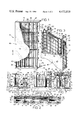
- FIG. 1 is a perspective view of the prefabricated load-bearing wall panel of the present invention with parts broken away.
- FIG. 2 is a sectional view taken along line 2--2 of FIG. 1.
- FIG. 3 is an enlarged perspective view of a portion of the wall panel with parts broken away.
- FIG. 4 is a front elevational view of two wall panels of the present invention with parts broken away.
- FIG. 5 is a sectional view taken along line 5--5 of FIG. 4.
- FIG. 6 is an enlarged front elevation of the anchor means for the wall panel of the present invention with the concrete layer and reinforcing mesh removed.
- FIG. 7 is a sectional view as taken along line 7--7 of FIG. 6.
- FIG. 8 is a sectional view as taken along line 8--8 of FIG. 7.
- FIG. 9 is a sectional view taken along line 9--9 of FIG. 4.
- FIG. 10 is a sectional view of the wall panel of the present invention showing the means for supporting windows above and below the wall panel.
- FIG. 1 shows a prefabricated load-bearing wall panel 10 having a structural frame 12.
- the frame 12 is generally rigid and consists of a plurality of spaced apart parallel elongated studs 14 secured together by a plurality of generally perpendicular braces 16.
- each stud 14 is preferably a steel column formed in cross section as a substantially C-shaped channel which has a back web wall 18 and parallel side walls 20 and 22 perpendicularly connected to the web wall 18.
- a bolster means is secured along the side wall 22 of each stud 14.
- Each bolster means comprises a plurality of substantially V-shaped spacers 30.
- Each spacer 30 in turn comprises a pair of legs, 32 and 34 respectively, joined at a juncture region 36.
- An elongated rod 38 is fastened to the juncture regions 36 of the spacers 30 of each bolster means.
- the free ends of legs 32 and 34 of the spacers 30 of each bolster means are fastened (welded) to the longitudinal edges of the side wall 22 of one of the studs 14 so that the juncture regions 36 all extend in the same direction outwardly from the studs 14, as shown in FIGS. 2 and 3.
- the spacers 30 are spaced apart along the length of both rod 38 and stud 14 and the rod 38 extends substantially parallel to and is spaced from the face of side wall 22 of the respective stud 14.
- a standard concrete reinforcing mesh 40 overlies and is bonded to each of the elongated rods 38.
- the mesh 40 is preferably comprised of vertical and horizontal wires welded together and the mesh 40 is welded at spaced intervals to the rods 38.
- the ends of the vertical wires of mesh 40 are welded to a top molding 42, which in turn is secured (also welded as shown) to a cap channel 43 extending across the upper end of the studs 14.
- the ends of the vertical wires of mesh 40 are welded to a bottom sill 44, which is secured to the lower end of studs 14.
- the mesh 40 for one wall panel is a unitary piece of welded steel mesh secured to the frame 12 along molding 42, sill 44, and through the bolster means of each stud 14.
- a thin, generally planar layer or slab of concrete 46 is held substantially parallel to the studs 14 of the wall panel 10.
- the concrete layer or slab has an outer face 48 and an opposite inner side 50 which faces and is spaced from the side walls 22 of the studs 14.
- the entire piece of reinforcing mesh 40 for one wall panel 10 and a portion (including the juncture region 36) of each V-shaped spacer 30 of the bolster means is embedded in the concrete layer 46 and provides a semi-rigid support for the layer 46 from the frame 12.
- the inner side 50 of the concrete layer 46 is spaced from the walls 22 of studs 14 (which lie generally on a common plane) by a gap 52.
- Each bolster means is partially embedded in the layer 46 so that the legs 32 and 34 of each V-shaped spacer 30 protrude a substantially similar amount (approximately equaling the gap 52) from the inner side 50 of the layer 46.
- the relative positioning of the various elements of the wall panel 10 is best shown in FIG. 1, where portions of the concrete layer or slab 46 and mesh 40 are broken away.
- the wall panel is formed by supporting the studs, bolster means and mesh in a casting bed, with the mesh facing down.
- a slurry of high strength concrete is poured into the bed to the proper depth to embed the mesh and form the layer. After the concrete hardens or sets, the panel, including the concrete layer is removed from the casting bed.
- a wall panel 10 assembled in this manner provides a composite structure wherein the concrete layer 46 can absorb substantial wind loading (loading perpendicular to the plane of the concrete layer 46) without requiring the frame 12 to be sufficiently strong to carry all of the load.
- the bolster means permits the concrete layer 46 to flex relative to the studs 14 in direction along the general plane of the layer 46, and additionally provides compressive and tensile support for the layer 46 on the studs 14 in a direction generally perpendicular to the general plane of the layer 46.
- this composite panel structure also allows the concrete layer 46 to respond to other changes in condition, such as temperature differentials, independently from the frame 12.
- the bolster means prevents building loads on the frame 12 (such as tension or compression on the studs 14) from being transferred directly to the concrete layer 46.
- a prefabricated load-bearing wall panel of this design also conserves energy in structures in which it is used.
- the depth of the studs 14 (defined by the space between walls 20 and 22 of the studs 14) can be filled with insulation or left as a dead air space.
- the gap 52 between the studs 14 and the inner side 50 of the concrete layer 46 provides an additional thermal break of air space so conduction of heat between the layer 46 and the studs 14 is minimized for energy conservation purposes.
- a series of cross members 53 are secured perpendicularly to the studs 14.
- the cross members 53 cooperate with the studs 14 to form a load transfer mechanism for transferring a portion of shear loads exerted on the frame 12 (in direction generally perpendicular to the length of studs 14 and parallel to the general plane of the layer 46) to the concrete layer 46 so that the studs 14 and the layer 46 each bear portions of the load.
- shear forces generally occur adjacent the roof line of a structure, and may result from wind loads on the walls of the building perpendicular to the wall panel 10 shown.
- the loads are carried by the cross members 53 to the studs 14 where a portion of the load is transferred through the legs 32 and 34 of the spacers 30 to the concrete layer 46.
- the studs 14 and layer 46 exhibit a composite reaction to shear loads on the wall panel 10.
- the V-shape of the legs of spacers 30 is an efficient design to transfer loads from the frame 12 to the concrete layer 46.
- the legs 32 and 34 of each spacer 30 are disposed at an 90° angle relative to each other (and 45° relative to the plane of the concrete layer) to provide the optimum load transfer.
- there is a sharing of loads on the bolster means all along the length of the studs 14 so that loads between the studs 14 and the concrete layer 46 are spread evenly across the plane of the layer 46. This load sharing reduuces the possibility of a "stress raiser" connection which leads to failure at any one point on the wall panel 10.
- FIG. 4 shows two wall panels 10 mounted adjacent each other with the outer faces 48 of their respective concrete layers 46 positioned substantially coplanar.
- the frames 12 of these wall panels 10 include additional support braces 54 positioned generally perpendicularly to the studs 14, as shown.
- Each support brace 54 is mounted upon the upper end of at least one shortened stud 56 in the frame 12.
- the shortened studs 56 and support braces 54 provide means on the frame 12 for supporting additional structural components on the frame 12, such as a horizontal roof or ceiling beam 58, as shown in FIGS. 4 and 5.
- a building's roof weight may be supported by the frame 12 by either the studs 14 (with the weight applied upon cap channel 43) or the studs 56 (with the weight applied upon the support braces 54).
- other means of supporting the roof or ceiling decking structure from the wall panels 10 are also possible.
- shortened studs 56 When the shortened studs 56 are the outermost studs at the side of a wall panel 10, additional stud sections 60 are secured to the shortened studs 56 to form a continuous support column from the the cap channel 43 to the bottom sill 44 in order to maintain the structural integrity of the frame 12.
- the shortened studs 56 and additional stud sections 60 also have bolster means secured thereon in the same manner as the studs 14. The relative positioning of these features are best shown in FIG. 4, where portions of the concrete layer 46 and mesh 40 are broken away.
- Each wall panel 10 is secured to a structural foundation 62 (which is a concrete slab as shown) by a U-shaped anchor 64 positioned at each bottom corner of the frame 12.
- FIG. 4 shows the relative position of the anchor 64 with respect to two adjacent wall panels 10, and FIGS. 6, 7 and 8 are enlarged views of the anchor 64 shown in FIG. 4.
- the U-shaped anchor 64 consists of a pair of generally parallel members 68 and 70 extending upwardly from a base portion 66.
- the members 68 and 70 are separately secured to the back web walls 18 of the outermost studs 56 (or the studs 14 in a panel as shown in FIG. 1) of the adjacent wall panels 10, as shown in FIGS. 6 and 7.
- Each wall panel 10 is secured to the anchor 64 so that the panel 10 is positioned over the foundation 62 in an upstanding generally vertical position, as shown in FIGS. 5 and 8.
- the wall panel 10 Prior to securing the anchor 64 to the studs 56, the wall panel 10 is adjustable vertically relative to the foundation 62 so that adjacent panels can be secured at substantially the same height relative to the foundation 62.
- the base portion 66 of anchor 64 is bonded to an anchor plate 72 which, in turn, is bonded to the foundation 62.
- the anchor plate 72 is shown embedded into the foundation 62.
- a bottom sill 44 (shaped as an angle iron) is secured to the lower ends of the studs of the frame 12.
- the sill 44 runs along the entire length of the bottom of the frame and has notches 74 at its outermost ends to accommodate the anchors 64, as best shown in FIG. 7.
- Each notch 74 and anchor 64 cooperate to align the outer faces 48 of adjacent wall panels substantially coplanar and thus provide a smooth and esthetic transition between adjacent concrete layers 46.
- Each sill 44 has an upstanding flange 76 adjacent the sides 20 of the studs 14 or 56 and a downwardly extending ramp 78 at the lower end of the concrete layer 46, as best shown in FIG. 8.
- the ramp 78 (to which the mesh 40 is bonded) provides a means for collecting and draining water that otherwise may be trapped in the gap 52 of the wall panel 10.
- the ramp 78 provides a run-off for water, such as condensation, to drain it away from the wall panel 10.
- the ramp 78 is contiguous to the lower edge of the concrete layer 46 and forms a stop or form for the slurry of concrete when it is poured.
- the cap channel 43, top molding 52, bottom sill 44, and concrete layer 46 all extend a similar distance past the outermost studs at each side of the wall panel 10.
- the frame 12 is thus completely hidden by the layer 46 when viewed from the normal outside of the wall panel 10, as shown in FIGS. 4 and 7.
- the small gap 80 between the side edges of the layers 46 of adjacent wall panels 10 is preferably caulked or filled for a weather seal that permits expansion and contraction to present a unitary face for the outside of a structure constructed with wall panels 10 of the present invention.
- a concrete layer 81 (which corresponds to the concrete layer 46) of one of the wall panels adjacent the corner is formed to integrally turn the corner. As shown in FIG. 9, the concrete layer 81 extends past the side of the frame 12 and has a corner portion 82 extending generally perpendicular to the plane of the concrete layer 81.
- the outermost stud 14 of the frame 12 at the corner is provided with two bolster means.
- a first bolster means 84 is secured to the side wall 22 of the outermost stud 14 as previously described and a second bolster means 86 is secured to the back web wall 18 of the stud 14 to provide a resilient means to support a bent portion of a concrete reinforcing mesh 83 (which corresponds to the mesh 40) embedded in the concrete layer 81 and the corner portion 82 of the concrete layer 81 from the frame 12.
- the corner portion 82 of the concrete layer 81 extends at right angles beyond the side wall 20 of the stud 14 for alignment with the side edge of the next adjacent concrete layer 46 around the corner of the building, as shown.
- the reinforcing mesh 83 is also integrally formed to bend around the corner for reinforcing the concrete layer 81 and corner portion 82, and is secured to the second bolster means 86 in the same manner as previously described.
- the wall panels can be used in multi-story buildings and supported on the framework of such buildings at the midsections of the panels.
- the upper part or the wall panel extends above the floor and supports windows or a glazing system
- the lower part of the wall panel extends below the floor and supports the tops of the windows or glazing system of the floor below.
- the concrete layer of the wall panel is formed to integrally extend past the top or bottom of its studs to form a generally horizontal mounting portion upon which window and door frames is secured.
- a concrete layer 87 (which corresponds to the concrete layer 46) has upper and lower generally horizontally extending portions 88 and 90.
- a reinforcing mesh 89 (which corresponds to the mesh 40) is embedded in the concrete layer 87 and is bent to have horizontally extending portions embedded in the portions 88 and 90 as shown.
- the studs 91 (which correspond to the studs 14) have cap channels 45 at both their upper and lower ends, and the horizontally extending portions of the mesh 89 are secured to the cap channels 45 at both ends by hook means 92.
- the horizontally extending portions 88 and 90 of the concrete layer 87 are spaced from the cap channels 45 by foam spacer blocks 94.
- the concrete layer 87 is fastened along the length of the studs 91 by bolster means as previously described. As shown, the generally horizontal portion 88 of the concrete layer 87 supports a window frame 96 for a window 98 above the wall panel. Similarly, the generally horizontally extending portion 90 of the concrete layer 87 supports a window frame 100 for a window 102 below the wall panel. The glazing system of a building is thus supported by the wall panels of the present invention, as shown in FIG. 10.
- FIG. 10 Means for supporting the wall panels in multi-story buildings are also shown in FIG. 10.
- a horizontal section 104 of a building's poured concrete floor is shown.
- the horizontal section 104 could be decking or a steel framework, however.
- the selected ones of the studs 91 of the each wall panel are secured to fasteners which in turn are supported on the horizontal section 104.
- the horizontal section 104 has embedded metal clips or a metal brace supported thereby and vertical angle is on brackets 106 are welded to the embedded metal parts at desired locations corresponding to the portion of selected ones of the studs 91.
- the brackets 106 are parallel to the studs and extend for a desired length downwardly.
- the vertical bracket (angle iron) 106 is additionally supported on the horizontal section 104 by a gusset or brace 108 welded to a clip on the horizontal section 104 extending downwardly from the horizontal section 104 to be welded to the corresponding vertical angle iron brackets 106, as shown in FIG. 10.
- the brackets 106 are welded to their desired studs while the wall panels are held in proper position.
- the brackets 106 can be adjusted to be vertical and properly positioned prior to the time they are welded to the provided portions of the horizontal section 104 and before gussets 108 are welded in place.
- panels of many different dimensions and shapes are possible: continuous flat panels, corner panels, panels with openings for windows or doors, and panels having designs formed in the outer face of the concrete layer.
- the panels of the present invention are light in weight, easier to transport and provide adequate space for insulation.
- the panels are open and easily insulated.
Landscapes
- Engineering & Computer Science (AREA)
- Architecture (AREA)
- Civil Engineering (AREA)
- Structural Engineering (AREA)
- Physics & Mathematics (AREA)
- Electromagnetism (AREA)
- Panels For Use In Building Construction (AREA)
Abstract
Description
______________________________________
Inventor      U.S. Pat. No.
______________________________________
Duphiney      1,578,964
Glass         2,121,962
Deutsch       2,192,183
Fromson       2,558,946
Monk, Jr.     3,162,982
Lanctot       3,378,982
Ott           3,885,369
Boarini       3,965,639
GangaRao      4,320,606
______________________________________
Claims (16)
Priority Applications (1)
| Application Number | Priority Date | Filing Date | Title |
|---|---|---|---|
| US06/379,896 US4472919A (en) | 1982-05-19 | 1982-05-19 | Prefabricated building panel |
Applications Claiming Priority (1)
| Application Number | Priority Date | Filing Date | Title |
|---|---|---|---|
| US06/379,896 US4472919A (en) | 1982-05-19 | 1982-05-19 | Prefabricated building panel |
Publications (1)
| Publication Number | Publication Date |
|---|---|
| US4472919A true US4472919A (en) | 1984-09-25 |
Family
ID=23499149
Family Applications (1)
| Application Number | Title | Priority Date | Filing Date |
|---|---|---|---|
| US06/379,896 Expired - Lifetime US4472919A (en) | 1982-05-19 | 1982-05-19 | Prefabricated building panel |
Country Status (1)
| Country | Link |
|---|---|
| US (1) | US4472919A (en) |
Cited By (70)
| Publication number | Priority date | Publication date | Assignee | Title |
|---|---|---|---|---|
| US4619032A (en) * | 1983-03-07 | 1986-10-28 | Fibrestone Incorporated | Method of forming a composite wall for a building structure |
| US4642960A (en) * | 1984-12-12 | 1987-02-17 | Wallover Iii Edwin M | Prefabricated building panel and method of making the same |
| US4700518A (en) * | 1982-09-03 | 1987-10-20 | Kajima Kensetsu Kabushiki Kaisha | Concrete panel having tile driven |
| WO1988001325A1 (en) * | 1986-08-14 | 1988-02-25 | Unan Pty Ltd. | Modular building system |
| US4970838A (en) * | 1990-01-05 | 1990-11-20 | Phillips Charles N | Reinforced concrete building and method of construction |
| US5248122A (en) * | 1989-06-22 | 1993-09-28 | Graham Tom S | Pre-attached form system for insulated concrete wall panel |
| ES2063711A2 (en) * | 1993-06-30 | 1995-01-01 | Palomera Ricardo Ceron | System for the prefabricated construction of buildings, and panels used in said construction |
| US5493836A (en) * | 1993-12-20 | 1996-02-27 | Lopez-Munoz; Humberto | Building system based upon preformed modules |
| US5669195A (en) * | 1994-10-04 | 1997-09-23 | N.V. Bekaert S.A. | Wire bead plaster, stucco and the like |
| US5799453A (en) * | 1996-07-12 | 1998-09-01 | Westerlund; Robert E. | Structure and method of fabrication |
| US5894704A (en) * | 1997-02-25 | 1999-04-20 | Watkins; Michael W. | Wall construction process |
| US5906081A (en) * | 1995-05-04 | 1999-05-25 | Ma-Rakennus J. Mantyla Ky | Wall construction and method of manufacturing a wall construction |
| USD422486S (en) * | 1998-02-05 | 2000-04-11 | Keel Manufacturing, Inc. | Ceiling grid wall clip |
| WO2000060186A1 (en) * | 1999-04-06 | 2000-10-12 | Simple Building Systems, Inc. | Building construction system |
| US6233892B1 (en) | 1997-10-25 | 2001-05-22 | The Namlyt Company | Structural panel system |
| WO2002020916A1 (en) * | 2000-09-07 | 2002-03-14 | Selwyn Reed | Modular building panel |
| US6443666B1 (en) * | 1998-09-16 | 2002-09-03 | William H. Smith | Reinforced concrete panel and method of manufacture |
| US6540445B1 (en) * | 2001-03-01 | 2003-04-01 | Eldon Boyd Evans, Jr. | Concrete silt fence |
| US6668507B2 (en) | 2000-12-08 | 2003-12-30 | Paulin A. Blanchet | Hurricane resistant precast composite building system |
| US20040040257A1 (en) * | 2002-08-29 | 2004-03-04 | Bui Thuan H. | Lightweight modular cementitious panel/tile for use in construction |
| US20040065043A1 (en) * | 2002-10-08 | 2004-04-08 | Joel Foderberg | Lightweight precast concrete wall panel system |
| US6729094B1 (en) * | 2003-02-24 | 2004-05-04 | Tex Rite Building Systems, Inc. | Pre-fabricated building panels and method of manufacturing |
| US6735914B2 (en) * | 2002-07-03 | 2004-05-18 | Peter J. Konopka | Load bearing wall |
| US20050000184A1 (en) * | 2000-01-10 | 2005-01-06 | Lakdas Nanayakkara | Metal stud frame element construction panel |
| US6857241B1 (en) * | 1999-07-13 | 2005-02-22 | Carlos Fradera Pellicer | Building panel and plant for the manufacture thereof |
| US20050050825A1 (en) * | 2003-03-31 | 2005-03-10 | Joel Foderberg | Channel-reinforced concrete wall panel system |
| US6920729B2 (en) | 2002-07-03 | 2005-07-26 | Peter J. Konopka | Composite wall tie |
| US20050235598A1 (en) * | 2001-10-23 | 2005-10-27 | Andrew Liggins | Wall construction method |
| US20050262998A1 (en) * | 2003-12-19 | 2005-12-01 | Jameel Ahmad | Protective structure and protective system |
| DE10032056B4 (en) * | 1999-07-10 | 2006-03-30 | Pilger, Martina | Wall for prefabricated house systems, as well as methods for mounting walls |
| WO2006049562A1 (en) * | 2004-11-03 | 2006-05-11 | Ncc Ab | Wall module |
| US20060185280A1 (en) * | 2004-05-11 | 2006-08-24 | Plastedil S.A. | Load bearing construction element, in particular for manufacturing building floors, and floor structure incorporating such element |
| WO2006105580A1 (en) * | 2004-10-15 | 2006-10-12 | Go Crete Pty Ltd | Wall panel |
| US20070044414A1 (en) * | 2005-08-27 | 2007-03-01 | Ruiz Antonio R | Building construction system and method of fabrication |
| US20080016802A1 (en) * | 2006-07-24 | 2008-01-24 | Rheaume Paul R | Building modular and panel system and method of construction thereof |
| US20080092471A1 (en) * | 2003-12-19 | 2008-04-24 | Jameel Ahmad | Protective structure and protective system |
| US7784223B1 (en) | 2000-05-31 | 2010-08-31 | Ramey Larry E | Three hundred mile per hour wind resistive building |
| WO2011028232A3 (en) * | 2009-08-23 | 2011-06-23 | Thuan Bui | Fastener for lightweight concrete panel and panel assembly |
| US20110197545A1 (en) * | 2010-01-06 | 2011-08-18 | Unistress Corporation | Embedded Mesh in Precast Walls |
| US20120058299A1 (en) * | 2009-03-17 | 2012-03-08 | Connovate Aps | Composite Sandwich Panel |
| US20130326985A1 (en) * | 2010-09-09 | 2013-12-12 | Crupe International (Ip) Gmbh | Aqueous gypsum plaster-cement composition and its use |
| US8733047B1 (en) * | 2013-12-20 | 2014-05-27 | Highland Technologies, LLC | Durable wall construction |
| US8733048B1 (en) * | 2013-12-20 | 2014-05-27 | Highland Technologies, LLC | Multi-story durable wall construction |
| US20140165490A1 (en) * | 2010-01-20 | 2014-06-19 | Propst Family Limited Partnership | Building panel system |
| US8904724B1 (en) * | 2013-12-20 | 2014-12-09 | Highland Technologies, LLC | Durable wall construction |
| US20150020475A1 (en) * | 2013-03-01 | 2015-01-22 | Shaw & Sons, Inc. | Architectural concrete wall and method of forming the same |
| US20150040493A1 (en) * | 2013-08-08 | 2015-02-12 | Heng-Sheng Kuo | Partition and construction method thereof |
| US8997422B1 (en) * | 2014-04-24 | 2015-04-07 | Daniel Kim | Building construction formed of prefab concrete forms |
| WO2015094396A1 (en) * | 2013-12-20 | 2015-06-25 | Highland Technologies, LLC | Durable wall construction |
| CN104763079A (en) * | 2015-03-11 | 2015-07-08 | 任志鹏 | Foldable assembled integral concrete shear wall structure |
| US20150211237A1 (en) * | 2014-01-27 | 2015-07-30 | Tai Ye Enterprises Ltd. | Wall unit used in construction |
| US9234349B1 (en) | 2013-08-30 | 2016-01-12 | Convergent Market Research, Inc. | Concrete panel system and method for forming reinforced concrete building components |
| CN105908867A (en) * | 2016-04-22 | 2016-08-31 | 东南大学 | Cold-formed thin-wall section steel composite sheet steel shear wall |
| CN106320568A (en) * | 2016-08-22 | 2017-01-11 | 北京迈瑞司建筑科技发展有限公司 | Production method of multi-rib composite wallboard |
| US9593487B2 (en) * | 2014-09-05 | 2017-03-14 | James F. Harvey | Modular building system |
| CN107152106A (en) * | 2017-07-20 | 2017-09-12 | 迈瑞司(北京)抗震住宅技术有限公司 | The close rib composite construction system of shaped steel and its keel unit, wall, assembly method |
| CN107246088A (en) * | 2017-06-28 | 2017-10-13 | 浙江绿筑集成科技有限公司 | A kind of prefabricated steel reinforced concrete shear walls |
| CN108277904A (en) * | 2018-03-19 | 2018-07-13 | 北京工业大学 | Assembled sash type light steel frame-bar-mat reinforcement-foamed concrete faced wall |
| CN108277903A (en) * | 2018-03-19 | 2018-07-13 | 北京工业大学 | Assembling truss type light steel frame-punching sheet metal-Combined concrete wall |
| CN108301533A (en) * | 2018-03-19 | 2018-07-20 | 北京工业大学 | Assembling truss type light steel frame-bar-mat reinforcement-Combined concrete wall |
| CN108316517A (en) * | 2018-03-19 | 2018-07-24 | 北京工业大学 | Prefabricated lattice light steel frame-perforated thin steel plate-foamed concrete composite wall |
| CN108547396A (en) * | 2018-03-19 | 2018-09-18 | 北京工业大学 | Assembling truss type light steel frame-bar-mat reinforcement-foamed concrete faced wall |
| CN108612226A (en) * | 2018-03-19 | 2018-10-02 | 北京工业大学 | Assembled sash type light steel frame-bar-mat reinforcement-Combined concrete wall |
| CN108625507A (en) * | 2018-03-19 | 2018-10-09 | 北京工业大学 | Assembled sash type light steel frame-punching sheet metal-Combined concrete wall |
| CN108643390A (en) * | 2018-03-19 | 2018-10-12 | 北京工业大学 | Assembling truss type light steel frame-punching sheet metal-foamed concrete faced wall |
| WO2018201817A1 (en) * | 2017-05-04 | 2018-11-08 | 浙江绿筑集成科技有限公司 | Assemblable shear wall formed by steel/concrete components, and horizontal splicing method therefor |
| US10184251B2 (en) * | 2003-03-31 | 2019-01-22 | Pn Ii, Inc. | Self supportive panel system |
| US10954665B1 (en) * | 2019-09-14 | 2021-03-23 | Kenneth Robert Kreizinger | Sprayed-in-place framed wall |
| US20230417044A1 (en) * | 2022-06-22 | 2023-12-28 | iHAUS MODULAR, LLC | Concrete-fillable prefabricated cartridges for constructing structural concrete buildings and construction methods therefor |
| US20250347111A1 (en) * | 2024-05-08 | 2025-11-13 | Onx, Inc. | Method and arrangement for forming precast concrete panels |
Citations (34)
| Publication number | Priority date | Publication date | Assignee | Title |
|---|---|---|---|---|
| US657827A (en) * | 1900-05-02 | 1900-09-11 | William Mccall | Metal-lath attachment and support. |
| US772476A (en) * | 1904-04-21 | 1904-10-18 | Thomas Podmore | Building-block. |
| US1169985A (en) * | 1913-07-15 | 1916-02-01 | Arthur M Mickelson | Process of constructing building-blocks. |
| US1578964A (en) * | 1925-07-29 | 1926-03-30 | Duphiney Philip | Ceiling hanger |
| US1940933A (en) * | 1932-02-23 | 1933-12-26 | United States Gypsum Co | Wall and ceiling construction |
| US1963609A (en) * | 1931-11-23 | 1934-06-19 | United States Gypsum Co | Building insulation |
| US1982104A (en) * | 1933-09-02 | 1934-11-27 | Fairfax Partition & Constructi | Wall construction |
| US2121962A (en) * | 1936-04-16 | 1938-06-28 | Cons Expanded Metal Companies | Soundproof wall structure and structural member for use therein |
| US2192183A (en) * | 1937-05-27 | 1940-03-05 | Deutsch Maurice | Method of making concrete slabs |
| US2388880A (en) * | 1941-08-14 | 1945-11-13 | United States Gypsum Co | Method of manufacturing surface ornamented acoustical tile |
| US2497887A (en) * | 1943-06-30 | 1950-02-21 | Hilpert Meler George | Paneled building construction |
| US2558946A (en) * | 1943-11-19 | 1951-07-03 | Fromson Bertram William | Reinforced cast structure |
| US2703003A (en) * | 1947-07-28 | 1955-03-01 | Frederick H Ruppel | Wall panel |
| US2909821A (en) * | 1958-03-07 | 1959-10-27 | Anders C Olsen | Device for securing lath panels or the like to metal supporting members |
| US3094813A (en) * | 1961-04-07 | 1963-06-25 | Van Rensselaer P Saxe | Bar joist |
| US3162982A (en) * | 1959-02-09 | 1964-12-29 | Jr Clarence B Monk | Load bearing multiple panel unit |
| US3232018A (en) * | 1962-11-13 | 1966-02-01 | Dominion Bridge Co Ltd | Resilient clip securing panels in spaced relation to wall studs |
| US3363371A (en) * | 1964-01-10 | 1968-01-16 | Villalobos Roberto Fajardo | Erection of prefabricated houses |
| US3378982A (en) * | 1966-07-06 | 1968-04-23 | Leon P. Lanctot | Masonry wall reinforcing and spacing strip |
| US3469000A (en) * | 1966-02-23 | 1969-09-23 | Albert R Smith | Method of making an exposed aggregate panel |
| US3732052A (en) * | 1970-02-24 | 1973-05-08 | Remy F Nfg Gmbh | Apparatus for the continuous manufacture of precast reinforced concrete products, particularly slabs and beams |
| US3737511A (en) * | 1972-01-11 | 1973-06-05 | T Dillon | Method of producing an ornamental concrete surface |
| US3739050A (en) * | 1970-03-13 | 1973-06-12 | T Koncz | Process and apparatus for making large area concrete panels |
| US3760540A (en) * | 1971-09-08 | 1973-09-25 | P Latoria | Pre-cast concrete building panels |
| US3825394A (en) * | 1972-11-24 | 1974-07-23 | F Pietrowiak | Installation for the manufacture of finished concrete components |
| US3885369A (en) * | 1973-03-08 | 1975-05-27 | Vigarex Ets | Structural element |
| US3965639A (en) * | 1973-07-27 | 1976-06-29 | United States Gypsum Company | Beam-reinforced ceiling panels |
| US4185423A (en) * | 1978-03-27 | 1980-01-29 | Systems Concept, Inc. | Lightweight building module |
| US4205040A (en) * | 1974-10-22 | 1980-05-27 | Ohbayashi-Gumi, Ltd. | Exposed aggregate finishing method for concrete |
| US4225301A (en) * | 1977-12-30 | 1980-09-30 | Fuchs & Co. Aktiengesellschaft Fur Elektro-Draht-Erzeugung Und Maschinenbau | Plant for producing fired brick blanks |
| JPS5613144A (en) * | 1979-07-16 | 1981-02-09 | Toyo Rubber Chem Ind Co Ltd | Installation for mold |
| US4255915A (en) * | 1978-04-18 | 1981-03-17 | Angelo Muriotto | Process for producing prefabricated panels and tridimensional elements for building and products obtained from said process |
| US4259050A (en) * | 1977-06-06 | 1981-03-31 | Mircea Borcoman | Multi-purpose installation for the manufacture of small and medium products of reinforced and unreinforced concrete |
| US4320606A (en) * | 1979-12-06 | 1982-03-23 | Home Crafts Corporation | Reinforced concrete panels and building constructed therewith |
-
1982
- 1982-05-19 US US06/379,896 patent/US4472919A/en not_active Expired - Lifetime
Patent Citations (34)
| Publication number | Priority date | Publication date | Assignee | Title |
|---|---|---|---|---|
| US657827A (en) * | 1900-05-02 | 1900-09-11 | William Mccall | Metal-lath attachment and support. |
| US772476A (en) * | 1904-04-21 | 1904-10-18 | Thomas Podmore | Building-block. |
| US1169985A (en) * | 1913-07-15 | 1916-02-01 | Arthur M Mickelson | Process of constructing building-blocks. |
| US1578964A (en) * | 1925-07-29 | 1926-03-30 | Duphiney Philip | Ceiling hanger |
| US1963609A (en) * | 1931-11-23 | 1934-06-19 | United States Gypsum Co | Building insulation |
| US1940933A (en) * | 1932-02-23 | 1933-12-26 | United States Gypsum Co | Wall and ceiling construction |
| US1982104A (en) * | 1933-09-02 | 1934-11-27 | Fairfax Partition & Constructi | Wall construction |
| US2121962A (en) * | 1936-04-16 | 1938-06-28 | Cons Expanded Metal Companies | Soundproof wall structure and structural member for use therein |
| US2192183A (en) * | 1937-05-27 | 1940-03-05 | Deutsch Maurice | Method of making concrete slabs |
| US2388880A (en) * | 1941-08-14 | 1945-11-13 | United States Gypsum Co | Method of manufacturing surface ornamented acoustical tile |
| US2497887A (en) * | 1943-06-30 | 1950-02-21 | Hilpert Meler George | Paneled building construction |
| US2558946A (en) * | 1943-11-19 | 1951-07-03 | Fromson Bertram William | Reinforced cast structure |
| US2703003A (en) * | 1947-07-28 | 1955-03-01 | Frederick H Ruppel | Wall panel |
| US2909821A (en) * | 1958-03-07 | 1959-10-27 | Anders C Olsen | Device for securing lath panels or the like to metal supporting members |
| US3162982A (en) * | 1959-02-09 | 1964-12-29 | Jr Clarence B Monk | Load bearing multiple panel unit |
| US3094813A (en) * | 1961-04-07 | 1963-06-25 | Van Rensselaer P Saxe | Bar joist |
| US3232018A (en) * | 1962-11-13 | 1966-02-01 | Dominion Bridge Co Ltd | Resilient clip securing panels in spaced relation to wall studs |
| US3363371A (en) * | 1964-01-10 | 1968-01-16 | Villalobos Roberto Fajardo | Erection of prefabricated houses |
| US3469000A (en) * | 1966-02-23 | 1969-09-23 | Albert R Smith | Method of making an exposed aggregate panel |
| US3378982A (en) * | 1966-07-06 | 1968-04-23 | Leon P. Lanctot | Masonry wall reinforcing and spacing strip |
| US3732052A (en) * | 1970-02-24 | 1973-05-08 | Remy F Nfg Gmbh | Apparatus for the continuous manufacture of precast reinforced concrete products, particularly slabs and beams |
| US3739050A (en) * | 1970-03-13 | 1973-06-12 | T Koncz | Process and apparatus for making large area concrete panels |
| US3760540A (en) * | 1971-09-08 | 1973-09-25 | P Latoria | Pre-cast concrete building panels |
| US3737511A (en) * | 1972-01-11 | 1973-06-05 | T Dillon | Method of producing an ornamental concrete surface |
| US3825394A (en) * | 1972-11-24 | 1974-07-23 | F Pietrowiak | Installation for the manufacture of finished concrete components |
| US3885369A (en) * | 1973-03-08 | 1975-05-27 | Vigarex Ets | Structural element |
| US3965639A (en) * | 1973-07-27 | 1976-06-29 | United States Gypsum Company | Beam-reinforced ceiling panels |
| US4205040A (en) * | 1974-10-22 | 1980-05-27 | Ohbayashi-Gumi, Ltd. | Exposed aggregate finishing method for concrete |
| US4259050A (en) * | 1977-06-06 | 1981-03-31 | Mircea Borcoman | Multi-purpose installation for the manufacture of small and medium products of reinforced and unreinforced concrete |
| US4225301A (en) * | 1977-12-30 | 1980-09-30 | Fuchs & Co. Aktiengesellschaft Fur Elektro-Draht-Erzeugung Und Maschinenbau | Plant for producing fired brick blanks |
| US4185423A (en) * | 1978-03-27 | 1980-01-29 | Systems Concept, Inc. | Lightweight building module |
| US4255915A (en) * | 1978-04-18 | 1981-03-17 | Angelo Muriotto | Process for producing prefabricated panels and tridimensional elements for building and products obtained from said process |
| JPS5613144A (en) * | 1979-07-16 | 1981-02-09 | Toyo Rubber Chem Ind Co Ltd | Installation for mold |
| US4320606A (en) * | 1979-12-06 | 1982-03-23 | Home Crafts Corporation | Reinforced concrete panels and building constructed therewith |
Non-Patent Citations (2)
| Title |
|---|
| Building Basics, brochure by Fabcon, Incorporated. * |
| Remember The Winter Wind, brochure by Fabcon, Incorporated. * |
Cited By (99)
| Publication number | Priority date | Publication date | Assignee | Title |
|---|---|---|---|---|
| US4700518A (en) * | 1982-09-03 | 1987-10-20 | Kajima Kensetsu Kabushiki Kaisha | Concrete panel having tile driven |
| US4619032A (en) * | 1983-03-07 | 1986-10-28 | Fibrestone Incorporated | Method of forming a composite wall for a building structure |
| US4642960A (en) * | 1984-12-12 | 1987-02-17 | Wallover Iii Edwin M | Prefabricated building panel and method of making the same |
| WO1988001325A1 (en) * | 1986-08-14 | 1988-02-25 | Unan Pty Ltd. | Modular building system |
| GB2207688A (en) * | 1986-08-14 | 1989-02-08 | Unan Pty Ltd | Modular building system |
| US5248122A (en) * | 1989-06-22 | 1993-09-28 | Graham Tom S | Pre-attached form system for insulated concrete wall panel |
| US4970838A (en) * | 1990-01-05 | 1990-11-20 | Phillips Charles N | Reinforced concrete building and method of construction |
| ES2063711A2 (en) * | 1993-06-30 | 1995-01-01 | Palomera Ricardo Ceron | System for the prefabricated construction of buildings, and panels used in said construction |
| US5493836A (en) * | 1993-12-20 | 1996-02-27 | Lopez-Munoz; Humberto | Building system based upon preformed modules |
| US5669195A (en) * | 1994-10-04 | 1997-09-23 | N.V. Bekaert S.A. | Wire bead plaster, stucco and the like |
| US5906081A (en) * | 1995-05-04 | 1999-05-25 | Ma-Rakennus J. Mantyla Ky | Wall construction and method of manufacturing a wall construction |
| US5799453A (en) * | 1996-07-12 | 1998-09-01 | Westerlund; Robert E. | Structure and method of fabrication |
| US5894704A (en) * | 1997-02-25 | 1999-04-20 | Watkins; Michael W. | Wall construction process |
| US6233892B1 (en) | 1997-10-25 | 2001-05-22 | The Namlyt Company | Structural panel system |
| USD422486S (en) * | 1998-02-05 | 2000-04-11 | Keel Manufacturing, Inc. | Ceiling grid wall clip |
| US6443666B1 (en) * | 1998-09-16 | 2002-09-03 | William H. Smith | Reinforced concrete panel and method of manufacture |
| US6151858A (en) * | 1999-04-06 | 2000-11-28 | Simple Building Systems | Building construction system |
| WO2000060186A1 (en) * | 1999-04-06 | 2000-10-12 | Simple Building Systems, Inc. | Building construction system |
| DE10032056B4 (en) * | 1999-07-10 | 2006-03-30 | Pilger, Martina | Wall for prefabricated house systems, as well as methods for mounting walls |
| US6857241B1 (en) * | 1999-07-13 | 2005-02-22 | Carlos Fradera Pellicer | Building panel and plant for the manufacture thereof |
| US20050000184A1 (en) * | 2000-01-10 | 2005-01-06 | Lakdas Nanayakkara | Metal stud frame element construction panel |
| US7051484B2 (en) * | 2000-01-10 | 2006-05-30 | Lakdas Nanayakkara | Metal stud frame element construction panel |
| US7784223B1 (en) | 2000-05-31 | 2010-08-31 | Ramey Larry E | Three hundred mile per hour wind resistive building |
| WO2002020916A1 (en) * | 2000-09-07 | 2002-03-14 | Selwyn Reed | Modular building panel |
| US6668507B2 (en) | 2000-12-08 | 2003-12-30 | Paulin A. Blanchet | Hurricane resistant precast composite building system |
| US6540445B1 (en) * | 2001-03-01 | 2003-04-01 | Eldon Boyd Evans, Jr. | Concrete silt fence |
| US20050235598A1 (en) * | 2001-10-23 | 2005-10-27 | Andrew Liggins | Wall construction method |
| US6735914B2 (en) * | 2002-07-03 | 2004-05-18 | Peter J. Konopka | Load bearing wall |
| US6920729B2 (en) | 2002-07-03 | 2005-07-26 | Peter J. Konopka | Composite wall tie |
| US20040040256A1 (en) * | 2002-08-29 | 2004-03-04 | Bui Thuan H. | Lightweight modular cementitious panel/tile for use in construction |
| US7493738B2 (en) | 2002-08-29 | 2009-02-24 | Bui Thuan H | Lightweight modular cementitious panel/tile for use in construction |
| US7770354B2 (en) | 2002-08-29 | 2010-08-10 | Bui Thuan H | Lightweight modular cementitious panel/tile for use in construction |
| US20040040257A1 (en) * | 2002-08-29 | 2004-03-04 | Bui Thuan H. | Lightweight modular cementitious panel/tile for use in construction |
| US20040065043A1 (en) * | 2002-10-08 | 2004-04-08 | Joel Foderberg | Lightweight precast concrete wall panel system |
| US6837013B2 (en) * | 2002-10-08 | 2005-01-04 | Joel Foderberg | Lightweight precast concrete wall panel system |
| US6729094B1 (en) * | 2003-02-24 | 2004-05-04 | Tex Rite Building Systems, Inc. | Pre-fabricated building panels and method of manufacturing |
| US20050050825A1 (en) * | 2003-03-31 | 2005-03-10 | Joel Foderberg | Channel-reinforced concrete wall panel system |
| US7028439B2 (en) | 2003-03-31 | 2006-04-18 | Joel Foderberg | Channel-reinforced concrete wall panel system |
| US10184251B2 (en) * | 2003-03-31 | 2019-01-22 | Pn Ii, Inc. | Self supportive panel system |
| US20050262998A1 (en) * | 2003-12-19 | 2005-12-01 | Jameel Ahmad | Protective structure and protective system |
| US6973864B1 (en) * | 2003-12-19 | 2005-12-13 | The Cooper Union For The Advancement Of Science And Art | Protective structure and protective system |
| US7562613B2 (en) | 2003-12-19 | 2009-07-21 | The Cooper Union For The Advancement Of Science And Art | Protective structure and protective system |
| US20080092471A1 (en) * | 2003-12-19 | 2008-04-24 | Jameel Ahmad | Protective structure and protective system |
| US20060185280A1 (en) * | 2004-05-11 | 2006-08-24 | Plastedil S.A. | Load bearing construction element, in particular for manufacturing building floors, and floor structure incorporating such element |
| US7784235B2 (en) * | 2004-05-11 | 2010-08-31 | Plastedil S.A. | Load bearing construction element, in particular for manufacturing building floors, and floor structure incorporating such element |
| WO2006105580A1 (en) * | 2004-10-15 | 2006-10-12 | Go Crete Pty Ltd | Wall panel |
| WO2006049562A1 (en) * | 2004-11-03 | 2006-05-11 | Ncc Ab | Wall module |
| US20070044414A1 (en) * | 2005-08-27 | 2007-03-01 | Ruiz Antonio R | Building construction system and method of fabrication |
| US20080016802A1 (en) * | 2006-07-24 | 2008-01-24 | Rheaume Paul R | Building modular and panel system and method of construction thereof |
| US20120058299A1 (en) * | 2009-03-17 | 2012-03-08 | Connovate Aps | Composite Sandwich Panel |
| WO2011028232A3 (en) * | 2009-08-23 | 2011-06-23 | Thuan Bui | Fastener for lightweight concrete panel and panel assembly |
| US8418428B2 (en) | 2010-01-06 | 2013-04-16 | Unitrex Corporation | Embedded mesh in precast walls |
| US8667764B2 (en) | 2010-01-06 | 2014-03-11 | Unistress Corporation | Embedded mesh in precast walls |
| US20110197545A1 (en) * | 2010-01-06 | 2011-08-18 | Unistress Corporation | Embedded Mesh in Precast Walls |
| US20140165490A1 (en) * | 2010-01-20 | 2014-06-19 | Propst Family Limited Partnership | Building panel system |
| US9097016B2 (en) * | 2010-01-20 | 2015-08-04 | Propst Family Limited Partnership | Building panel system |
| US20130326985A1 (en) * | 2010-09-09 | 2013-12-12 | Crupe International (Ip) Gmbh | Aqueous gypsum plaster-cement composition and its use |
| US9027303B2 (en) * | 2010-09-09 | 2015-05-12 | Crupe International (Ip) Gmbh | Aqueous gypsum plaster-cement composition and its use |
| US9487951B2 (en) | 2013-03-01 | 2016-11-08 | Shaw & Sons, Inc. | Architectural concrete wall and method of forming the same |
| US20150020475A1 (en) * | 2013-03-01 | 2015-01-22 | Shaw & Sons, Inc. | Architectural concrete wall and method of forming the same |
| US9315996B2 (en) * | 2013-08-08 | 2016-04-19 | Heng-Sheng Kuo | Partition and construction method thereof |
| US20150040493A1 (en) * | 2013-08-08 | 2015-02-12 | Heng-Sheng Kuo | Partition and construction method thereof |
| US9234349B1 (en) | 2013-08-30 | 2016-01-12 | Convergent Market Research, Inc. | Concrete panel system and method for forming reinforced concrete building components |
| WO2015094396A1 (en) * | 2013-12-20 | 2015-06-25 | Highland Technologies, LLC | Durable wall construction |
| US8733048B1 (en) * | 2013-12-20 | 2014-05-27 | Highland Technologies, LLC | Multi-story durable wall construction |
| WO2015094395A1 (en) * | 2013-12-20 | 2015-06-25 | Highland Technologies, Llc. | Multi-story durable wall construction |
| US8904724B1 (en) * | 2013-12-20 | 2014-12-09 | Highland Technologies, LLC | Durable wall construction |
| US8733047B1 (en) * | 2013-12-20 | 2014-05-27 | Highland Technologies, LLC | Durable wall construction |
| US20150211237A1 (en) * | 2014-01-27 | 2015-07-30 | Tai Ye Enterprises Ltd. | Wall unit used in construction |
| US8997422B1 (en) * | 2014-04-24 | 2015-04-07 | Daniel Kim | Building construction formed of prefab concrete forms |
| US9593487B2 (en) * | 2014-09-05 | 2017-03-14 | James F. Harvey | Modular building system |
| US20170152659A1 (en) * | 2014-09-05 | 2017-06-01 | James F. Harvey | Modular building system |
| US10156073B2 (en) * | 2014-09-05 | 2018-12-18 | James F. Harvey | Modular building system |
| CN104763079A (en) * | 2015-03-11 | 2015-07-08 | 任志鹏 | Foldable assembled integral concrete shear wall structure |
| CN105908867A (en) * | 2016-04-22 | 2016-08-31 | 东南大学 | Cold-formed thin-wall section steel composite sheet steel shear wall |
| CN106320568A (en) * | 2016-08-22 | 2017-01-11 | 北京迈瑞司建筑科技发展有限公司 | Production method of multi-rib composite wallboard |
| CN106320568B (en) * | 2016-08-22 | 2018-09-28 | 北京迈瑞司建筑科技发展有限公司 | The production method of close rib composite wall board |
| WO2018201817A1 (en) * | 2017-05-04 | 2018-11-08 | 浙江绿筑集成科技有限公司 | Assemblable shear wall formed by steel/concrete components, and horizontal splicing method therefor |
| CN107246088A (en) * | 2017-06-28 | 2017-10-13 | 浙江绿筑集成科技有限公司 | A kind of prefabricated steel reinforced concrete shear walls |
| CN107152106A (en) * | 2017-07-20 | 2017-09-12 | 迈瑞司(北京)抗震住宅技术有限公司 | The close rib composite construction system of shaped steel and its keel unit, wall, assembly method |
| CN107152106B (en) * | 2017-07-20 | 2023-09-05 | 迈瑞司(北京)抗震住宅技术有限公司 | Profile steel multi-ribbed composite structure system, keel unit, wall body and assembly method |
| CN108547396A (en) * | 2018-03-19 | 2018-09-18 | 北京工业大学 | Assembling truss type light steel frame-bar-mat reinforcement-foamed concrete faced wall |
| CN108625507B (en) * | 2018-03-19 | 2020-08-21 | 北京工业大学 | Prefabricated sash type light steel frame-punched sheet steel-concrete composite wall |
| CN108625507A (en) * | 2018-03-19 | 2018-10-09 | 北京工业大学 | Assembled sash type light steel frame-punching sheet metal-Combined concrete wall |
| CN108643390A (en) * | 2018-03-19 | 2018-10-12 | 北京工业大学 | Assembling truss type light steel frame-punching sheet metal-foamed concrete faced wall |
| CN108316517A (en) * | 2018-03-19 | 2018-07-24 | 北京工业大学 | Prefabricated lattice light steel frame-perforated thin steel plate-foamed concrete composite wall |
| CN108301533A (en) * | 2018-03-19 | 2018-07-20 | 北京工业大学 | Assembling truss type light steel frame-bar-mat reinforcement-Combined concrete wall |
| CN108277903A (en) * | 2018-03-19 | 2018-07-13 | 北京工业大学 | Assembling truss type light steel frame-punching sheet metal-Combined concrete wall |
| CN108612226B (en) * | 2018-03-19 | 2020-08-21 | 北京工业大学 | Assembled frame type light steel frame-reinforcing mesh-concrete combined wall |
| CN108277903B (en) * | 2018-03-19 | 2020-08-21 | 北京工业大学 | Prefabricated truss type light steel frame - punched thin steel plate - concrete composite wall |
| CN108612226A (en) * | 2018-03-19 | 2018-10-02 | 北京工业大学 | Assembled sash type light steel frame-bar-mat reinforcement-Combined concrete wall |
| CN108277904B (en) * | 2018-03-19 | 2020-09-25 | 北京工业大学 | Prefabricated sash type light steel frame-reinforced mesh-foamed concrete composite wall |
| CN108547396B (en) * | 2018-03-19 | 2020-09-25 | 北京工业大学 | Prefabricated truss light steel frame-reinforced mesh-foamed concrete composite wall |
| CN108316517B (en) * | 2018-03-19 | 2020-09-25 | 北京工业大学 | Assembled sash type light steel frame-punched sheet steel-foamed concrete composite wall |
| CN108643390B (en) * | 2018-03-19 | 2020-09-25 | 北京工业大学 | Assembled truss type light steel frame-punched thin steel plate-foamed concrete combined wall |
| CN108277904A (en) * | 2018-03-19 | 2018-07-13 | 北京工业大学 | Assembled sash type light steel frame-bar-mat reinforcement-foamed concrete faced wall |
| US10954665B1 (en) * | 2019-09-14 | 2021-03-23 | Kenneth Robert Kreizinger | Sprayed-in-place framed wall |
| US20230417044A1 (en) * | 2022-06-22 | 2023-12-28 | iHAUS MODULAR, LLC | Concrete-fillable prefabricated cartridges for constructing structural concrete buildings and construction methods therefor |
| US20250347111A1 (en) * | 2024-05-08 | 2025-11-13 | Onx, Inc. | Method and arrangement for forming precast concrete panels |
Similar Documents
| Publication | Publication Date | Title |
|---|---|---|
| US4472919A (en) | Prefabricated building panel | |
| US4674250A (en) | Modular building panel | |
| US4813193A (en) | Modular building panel | |
| US5335472A (en) | Concrete walls for buildings and method of forming | |
| US3377755A (en) | Prefabricated building units including prestressed floor panels with upstanding end members connected by tension means | |
| US3893271A (en) | Basic beam structural member and structures built therefrom | |
| US4019293A (en) | Building modules and structure embodying such modules | |
| US20070210237A1 (en) | Insulated wall assembly | |
| US2351856A (en) | Panel-wall building construction | |
| CZ282182B6 (en) | Metal-sheet structural element and process for producing thereof | |
| US4702058A (en) | Thermal structural wall panel | |
| FI60904C (en) | BYGGBLOCK OCH MODULSYSTEM FOER HUSBYGGNAD SAMT SAETT ATT TILLVERKA MODULBLOCK | |
| US3397500A (en) | Building structure with alternating structural members and panels in compression | |
| EA013175B1 (en) | Outer multi-story frame building wall of arcos system and method of erection thereof | |
| US8727759B1 (en) | Fully integrated structural building system | |
| RU2155256C2 (en) | Structural system for construction of buildings, particularly, single-family houses | |
| RU98115133A (en) | CONSTRUCTION SYSTEM FOR BUILDING BUILDINGS, IN PARTICULAR ONE-FAMILY HOUSES | |
| NL8120014A (en) | METHOD FOR ESTABLISHING A BUILDING AND APPARATUS FOR PERFORMING THE METHOD | |
| CN115341684B (en) | Externally hung transverse sandwich wallboard structure for bearing windows and house building | |
| EP0940516A1 (en) | A structural panel | |
| US20070186497A1 (en) | In-fill wall system | |
| RU2751299C1 (en) | Panel-frame system and method for its application for establishing walls of low-rise buildings | |
| JPH09125567A (en) | Wall panel and its installation structure | |
| GB2121851A (en) | Monocoque building method | |
| RU2247197C2 (en) | Balcony |
Legal Events
| Date | Code | Title | Description |
|---|---|---|---|
| AS | Assignment |
Owner name: CON-TEX ELEMENTS, INC., P.O. BOX 422, CHISAGO CITY Free format text: ASSIGNMENT OF ASSIGNORS INTEREST.;ASSIGNOR:NOURSE, JACK T.;REEL/FRAME:004079/0373 Effective date: 19830111 |
|
| STCF | Information on status: patent grant |
Free format text: PATENTED CASE |
|
| FEPP | Fee payment procedure |
Free format text: PAYOR NUMBER ASSIGNED (ORIGINAL EVENT CODE: ASPN); ENTITY STATUS OF PATENT OWNER: SMALL ENTITY |
|
| REMI | Maintenance fee reminder mailed | ||
| FPAY | Fee payment |
Year of fee payment: 4 |
|
| SULP | Surcharge for late payment | ||
| FPAY | Fee payment |
Year of fee payment: 8 |
|
| AS | Assignment |
Owner name: ENGINEERED WALL CORPORATION, MINNESOTA Free format text: ASSIGNMENT OF ASSIGNORS INTEREST;ASSIGNOR:CHISAGO COUNTY BANK;REEL/FRAME:007577/0503 Effective date: 19920615 |
|
| AS | Assignment |
Owner name: ENGINEERED WALL CORPORATION, MINNESOTA Free format text: ASSIGNMENT OF ASSIGNORS INTEREST;ASSIGNOR:CHISAGO COUNTY STATE BANK;REEL/FRAME:007677/0537 Effective date: 19920615 Owner name: CHISAGO COUNTY STATE BANK, MINNESOTA Free format text: ASSIGNMENT THROUGH BANKRUPTCY;ASSIGNOR:CON-TEX ELEMENTS, INC.;REEL/FRAME:007677/0545 Effective date: 19910116 |
|
| FPAY | Fee payment |
Year of fee payment: 12 |
|
| AS | Assignment |
Owner name: HAMILTON FORM CO., INC., TEXAS Free format text: ASSIGNMENT OF ASSIGNORS INTEREST;ASSIGNOR:ENGINEERED WALL CORPORATION;REEL/FRAME:011190/0477 Effective date: 20000528 |