US4470717A - Web seam for sheet-metal parts and method for producing the same - Google Patents
Web seam for sheet-metal parts and method for producing the same Download PDFInfo
- Publication number
- US4470717A US4470717A US06/516,668 US51666883A US4470717A US 4470717 A US4470717 A US 4470717A US 51666883 A US51666883 A US 51666883A US 4470717 A US4470717 A US 4470717A
- Authority
- US
- United States
- Prior art keywords
- flange
- web
- seam
- sheet metal
- connecting means
- Prior art date
- Legal status (The legal status is an assumption and is not a legal conclusion. Google has not performed a legal analysis and makes no representation as to the accuracy of the status listed.)
- Expired - Fee Related
Links
- 239000002184 metal Substances 0.000 title claims abstract description 51
- 238000004519 manufacturing process Methods 0.000 title description 4
- 238000005452 bending Methods 0.000 claims abstract description 13
- 238000005304 joining Methods 0.000 claims abstract description 5
- 238000003466 welding Methods 0.000 claims description 15
- 239000000853 adhesive Substances 0.000 claims description 6
- 230000001070 adhesive effect Effects 0.000 claims description 6
- 239000000463 material Substances 0.000 claims description 2
- 238000000034 method Methods 0.000 abstract description 11
- 239000004568 cement Substances 0.000 abstract 2
- 238000010521 absorption reaction Methods 0.000 description 4
- 238000010276 construction Methods 0.000 description 3
- 229910000831 Steel Inorganic materials 0.000 description 2
- 230000015572 biosynthetic process Effects 0.000 description 2
- 238000012986 modification Methods 0.000 description 2
- 230000004048 modification Effects 0.000 description 2
- 230000002250 progressing effect Effects 0.000 description 2
- 239000010959 steel Substances 0.000 description 2
- 238000004026 adhesive bonding Methods 0.000 description 1
- 230000003111 delayed effect Effects 0.000 description 1
- 230000000694 effects Effects 0.000 description 1
- 239000003822 epoxy resin Substances 0.000 description 1
- 230000001771 impaired effect Effects 0.000 description 1
- 230000000149 penetrating effect Effects 0.000 description 1
- 229920000647 polyepoxide Polymers 0.000 description 1
- 239000004814 polyurethane Substances 0.000 description 1
- 229920002635 polyurethane Polymers 0.000 description 1
- 230000008092 positive effect Effects 0.000 description 1
- 230000000750 progressive effect Effects 0.000 description 1
- 230000002035 prolonged effect Effects 0.000 description 1
- 238000004826 seaming Methods 0.000 description 1
- 230000000087 stabilizing effect Effects 0.000 description 1
Images

Classifications
-
- B—PERFORMING OPERATIONS; TRANSPORTING
- B23—MACHINE TOOLS; METAL-WORKING NOT OTHERWISE PROVIDED FOR
- B23K—SOLDERING OR UNSOLDERING; WELDING; CLADDING OR PLATING BY SOLDERING OR WELDING; CUTTING BY APPLYING HEAT LOCALLY, e.g. FLAME CUTTING; WORKING BY LASER BEAM
- B23K33/00—Specially-profiled edge portions of workpieces for making soldering or welding connections; Filling the seams formed thereby
- B23K33/004—Filling of continuous seams
- B23K33/008—Filling of continuous seams for automotive applications
Definitions
- the present invention relates to a seam arrangement and, more particularly, to a web seam for sheet-metal parts and the process of making the same.
- the seam is formed by a triple layer web projecting from a surface of the sheet metal part, with the respective layers being formed from a first flange of one sheet metal part and a second flange of another sheet metal part.
- the second flange is folded over in a U-shape and extends over the first flange with the first flange and a leg of the U-shaped second flange initially joining the sheet metal parts by their being separately connected by spot welding or cementing.
- the final securement of the flange involves the welding or cementing of both legs of the U-shaped flange to the first flange.
- a web seam in an intermediate step in the manufacture of a vehicle roof rain channel is proposed in German Pat. No. 855,235, wherein a curved roof panel with a flange is first tack welded by means of an electric spot welding to a portion of a Z-shaped roof frame of a motor vehicle body. Then by bending a projecting over hanging flange of the roof frame over the the flange of the roof panel, a roof edge is obtained having three times the sheet metal thickness.
- the aim underlying the present invention essentially resides in providing a high strength web seam and a method of producing such seam for thin-walled sheet metal joints, which seam withstands high peak loads and has a high energy absorption capacity.
- weld spots secure the triple layer web in the finished configuration, which weld spots attack all three layers simultaneously.
- An intermediate step in construction includes the spot welding of a first flange to a portion of a second flange prior to the second flange being formed into a generally U-shaped configuration and the welding of the triple layer web.
- the flange of the first sheet metal part is tacked onto an approximately twice as thick flange of a second sheet metal part, with a projecting portion of the second flange being thereafter folded back onto a rear side of the first flange.
- the web seam is then welded together by spot welding, with the spot welding penetrating and securing all three layers.
- a folded seam is obtained having different bonds extending across two and across three layers of a multilayer joint.
- the first band accross double layers is, applied as a tacking and serves essentially for stabilizing the seam during the folding over of the third layer of ply, i.e., the projecting portion of the second flange.
- the weld seam of the present invention upon the application of tensile stresses at right angles to the weld seam, only the bonds between two layers of the web would initially be torn apart or severed while the bonds between the other two layers are still maintained. In situations where tensile stresses are applied over a long time period or are of a greater magnitude, the three bent portions of the web seam are pulled into a stretched position or condition. In a final stage of a stressing process, subsequent to the seam being pulled into a stretched condition, the existing bonds are placed under a shear stress and thus withstand a high peak load which is about three and one half times greater than the peak loads which a double layer spot weld seam is capable of withstanding.
- the second spot welds of a spot welded seam may lie approximately along a same line as the first spot welds so that all weld spots are simultaneously load bearing in case a stress is exerted on the seam.
- a folded-back projection portion of the second flange may, in accordance with the present invention, be provided with cross cut outs or notches at a spacing corresponding to a pitch gap of the weld spots. Consequently, only relatively short flange lengths need to be worked in one operating cycle with such flange lengths, in a case of joining relatively large parts, being located in a series at intervals along an extension of the weld seam and selectively folded over section by section.
- the thus-produced triple layer flange is connected by weld spots, section by section, until the spot welded web seam extends over the entire component.
- a bending diameter of the folded back over hang or projecting portion may be larger than a single-sheet thickness and, preferably, is twice the sheet metal thickness since when using a moderately strong cold forming technique, the energy absorption capacity of the material is less greatly impaired.
- the apparatus for producing such seam may be fashioned, for example, as a seam-welding robot, wherein the required electrode force can simultaneously be utilized as a force for compressing the fold.
- a larger bending diameter of the folded-back sheet metal overhang or projecting portion has a positive effect on the strength of the web seam.
- the flange of the first sheet metal part is tacked onto the flange of the second sheet metal part, which flange is approximately twice as wide so as to enable the projecting portion of the second flange to be thereafter folded back onto a rear side of the first flange.
- the rearward or backward folding may be effected in sections in accordance with a progression of the operation during spot welding.
- Folded flanges produced in accordance with the process of the present invention may be economically and advantageously used, for example, especially in the construction of motor vehicle bodies, due to a higher load bearing capacity of the spot welds.
- the second sheet metal part may be provided, while being punched out as a sheet metal blank, with the cross cut outs or notches at the edge forming the overhang or projecting portion of the second flange.
- These cross cut outs may correspond to an operating cycle distance of the welding tool.
- the flange of the second metal sheet is tacked, while the overhang or projecting portion is folded back in a preceding section and the triple layer spot welding operation is performed.
- Another object of the present invention resides in providing a web seam for sheet metal parts which is simple in construction and therefore relatively inexpensive to manufacture.
- Yet another object of the present invention resides in providing a process for producing a web seam for sheet metal parts which may be carried out in an economical and efficient manner.
- a further object of the present invention resides in providing a weld seam for sheet metal parts which is capable of withstanding high peak loads and has a high energy absorption capacity.
- Yet a further object of the present invention resides in providing a spot weld web seam for sheet metal which when subjected to tensile stresses at generally right angles thereto tends to open by bending and then tearing of the spot welds through the sheet metal.
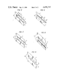
- FIG. 1 is a cross sectional view of a spot welded web seam constructed in accordance with the present invention for thin-walled sheet metal parts, in a semi-finished stage, tacked by spot welds;
- FIG. 2 is a cross sectional view of the spot welded web seam of FIG. 1 in a finished stage
- FIG. 3 is a top view of spot welded web seam in a sectionally progressing manufacturing mode
- FIG. 4 is an enlarged cross sectional view of spot welded web seam in accordance with the present invention showing a bending diameter which is greater than the flange thickness;
- FIGS. 5-9 show progressive stages of energy absorption of a web seam according to the instant invention when tensile stress of a magnitude capable of causing deformation is incurred.
- the seam includes a triple layer web generally designated by the reference numeral 3 projecting from a surface of the joined parts 1, 2 including a first flange 4 of one sheet metal part 1 and a second flange 6 of the other sheet metal part 2.
- the second flange 6 preferably has twice the width of the first flange 1 and is tacked to the first flange 4 by means of a series of spot welds 5 or by a suitable adhesive.
- An overhang of the second flange 6 extending beyond a free end of the flange 4 is subsequently folded back in a U-configuration onto the first flange 4 and joined to the first flange 4.
- the joining of the folded back over portion of the second flange 6 to the first flange 4 is accomplished by a series of weld spots 7 which connects all three layers of the sheet metal, with the spot welds 7 being arranged, if the first weld spots are used, preferably in series with the first spot welds 5.
- a bending diameter 8 may be maintained larger than a single thickness T of the sheet metal parts 1, 2.
- this bending diameter is twice the thickness T. It is understood that in vehicle bodies, the sheet metal parts are usually of the same gauge of steel. However, the same may be used with parts having different thicknesses, wherein the bending diameter is preferably twice the thickness of the intermediate flange, i.e., flange 4.
- the second sheet metal part 2 while being punched out as a blank, may, as shown most clearly in FIG. 3, be provided with cross cut outs or notches 9 at the projecting or overhanging portion of the flange 6 so as to enable a formation of the web seam to take place in a sectionally progressing fashion.
- tack spot welds 5 or after gluing the parts 1 and 2 together by a suitable adhesive
- another operating cycle section or distance is tacked while, in the first already tacked section, the projecting or overhanging portion of the second flange 6 is folded back into a U-shape onto the first flange 5 and attached by spot welds 7 which connect all three layers of the sheet metal.
- a compressing of the rearward folded projecting portion of the flange 6 can be effected in the arrangement of the present invention by the welding electrodes which perform the spot welds 7. After completing a welding operation by providing the spot welds 7, the weld-seaming tool, which may be arranged in an industrial robot, is shifted by one section.
- FIGS. 5-9 wherein a seam according to the instant invention, subjected to tensile stresses, is shown in sequential stages of deformation to tensile stress.
- the tensile stress is depicted by arrows extending in opposite directions and designated by S.
- the seam is under stress but at this instant undeformed.
- the spot welds begin to tear through the sheet metal and the folds in the sheet metal begin to open.
- the seam begins pulling open where flange 6 and flange 4 first abut.
Landscapes
- Engineering & Computer Science (AREA)
- Mechanical Engineering (AREA)
- Resistance Welding (AREA)
- Rigid Containers With Two Or More Constituent Elements (AREA)
- Body Structure For Vehicles (AREA)
- Butt Welding And Welding Of Specific Article (AREA)
Applications Claiming Priority (2)
| Application Number | Priority Date | Filing Date | Title |
|---|---|---|---|
| DE3021529 | 1980-06-07 | ||
| DE3021529A DE3021529C2 (de) | 1980-06-07 | 1980-06-07 | Verfahren zum Herstellen einer Stegnaht für Blechbauteile |
Related Parent Applications (1)
| Application Number | Title | Priority Date | Filing Date |
|---|---|---|---|
| US06271357 Continuation | 1981-06-08 |
Publications (1)
| Publication Number | Publication Date |
|---|---|
| US4470717A true US4470717A (en) | 1984-09-11 |
Family
ID=6104129
Family Applications (1)
| Application Number | Title | Priority Date | Filing Date |
|---|---|---|---|
| US06/516,668 Expired - Fee Related US4470717A (en) | 1980-06-07 | 1983-07-25 | Web seam for sheet-metal parts and method for producing the same |
Country Status (4)
| Country | Link |
|---|---|
| US (1) | US4470717A (enExample) |
| JP (1) | JPS5725292A (enExample) |
| DE (1) | DE3021529C2 (enExample) |
| FR (1) | FR2483825A1 (enExample) |
Cited By (15)
| Publication number | Priority date | Publication date | Assignee | Title |
|---|---|---|---|---|
| US4566623A (en) * | 1981-05-27 | 1986-01-28 | Lucas Industries Limited | Method of producing a metal tube and flange assembly |
| US4714287A (en) * | 1985-03-23 | 1987-12-22 | Daimler-Benz Aktiengesellschaft | Bending bar to be used as a bumper of a vehicle |
| US4738560A (en) * | 1984-10-12 | 1988-04-19 | Bayerische Motoren Werke Ag | Welding seam for the connection of two thin sheet metal members |
| US5184766A (en) * | 1990-03-31 | 1993-02-09 | Mazda Motor Corporation | Assembly line construction and method for assembling automotive vehicle bodies |
| US6368008B1 (en) * | 2000-05-24 | 2002-04-09 | Daimlerchrysler Corporation | Sealed edge joint between two metal panels |
| US6592171B1 (en) | 2002-02-07 | 2003-07-15 | Caterpillar Inc. | Dump body structure for an off-highway truck |
| RU2218252C1 (ru) * | 2002-04-04 | 2003-12-10 | Открытое акционерное общество "Магнитогорский металлургический комбинат" | Способ соединения полос |
| US7121004B1 (en) * | 1997-11-24 | 2006-10-17 | Columbia Manufacturing Corp. | Method of fabricating security door |
| US20070252410A1 (en) * | 2006-02-07 | 2007-11-01 | Gambatese Brady J | Vehicle rear window body structure |
| US20140333095A1 (en) * | 2009-04-03 | 2014-11-13 | GM Global Technology Operations LLC | Method for producing a body part of a vehicle and body part of a vehicle |
| CN104668380A (zh) * | 2013-11-28 | 2015-06-03 | 铃木株式会社 | 板构件的接合方法 |
| US20150314363A1 (en) * | 2014-04-30 | 2015-11-05 | GM Global Technology Operations LLC | Method of forming a vehicle body structure from a pre-welded blank assembly |
| CN107695614A (zh) * | 2016-08-08 | 2018-02-16 | 储德宝 | 一种多层金属板的结合方法 |
| US10894566B2 (en) * | 2015-10-12 | 2021-01-19 | Bayerische Motoren Werke Aktiengesellschaft | Arrangement for connecting two vehicle body components and method for producing a sheet metal component having a doubled joining flange |
| US12515273B2 (en) | 2019-03-27 | 2026-01-06 | Nippon Steel Corporation | Joint structure, automotive component, and joint structure manufacturing method |
Families Citing this family (3)
| Publication number | Priority date | Publication date | Assignee | Title |
|---|---|---|---|---|
| EP0351938B1 (en) * | 1988-07-14 | 1994-04-20 | Showa Aluminum Kabushiki Kaisha | An aluminum heat exchanger |
| JP2001336688A (ja) | 2000-05-30 | 2001-12-07 | Tokai Rubber Ind Ltd | 樹脂ホースの接続方法およびそれを用いた樹脂ホースの接続構造 |
| FR3148566A1 (fr) * | 2023-05-11 | 2024-11-15 | Psa Automobiles Sa | Dispositif de renforcement de feuillure de structure de véhicule automobile. |
Citations (5)
| Publication number | Priority date | Publication date | Assignee | Title |
|---|---|---|---|---|
| US1933484A (en) * | 1932-04-14 | 1933-10-31 | Budd Edward G Mfg Co | Method of welding |
| DE855235C (de) * | 1950-06-13 | 1952-11-10 | Daimler Benz Ag | Handgeraet zum Abbiegen von Blechraendern |
| US3132236A (en) * | 1961-11-20 | 1964-05-05 | Budd Co | Method for eliminating surface defects associated with indirect welding |
| US4072787A (en) * | 1977-01-03 | 1978-02-07 | The United States Of America As Represented By The Secretary Of The Army | Laminated wall tubing |
| US4352003A (en) * | 1979-09-17 | 1982-09-28 | Ductmate Industries, Inc. | Method for positioning and securing components of a workpiece |
Family Cites Families (3)
| Publication number | Priority date | Publication date | Assignee | Title |
|---|---|---|---|---|
| DE347961C (de) * | 1920-01-22 | 1922-01-28 | Metallhuette Baer & Co Kommand | Verfahren zum Bilden von Schweissnaehten |
| DE733200C (de) * | 1940-12-15 | 1943-03-20 | J A Schmalbach Blechwarenwerke | Verfahren zum Einschweissen von Boeden (oder Deckeln) in die Ruempfe von Blechgefaessen, insbesondere Konservendosen |
| AT360310B (de) * | 1977-03-30 | 1980-01-12 | Atlas Blech Center Gmbh | Verfahren zur herstellung von blechprofilen mit geschlossenem umfang |
-
1980
- 1980-06-07 DE DE3021529A patent/DE3021529C2/de not_active Expired
-
1981
- 1981-06-04 FR FR8111064A patent/FR2483825A1/fr active Granted
- 1981-06-05 JP JP8586681A patent/JPS5725292A/ja active Pending
-
1983
- 1983-07-25 US US06/516,668 patent/US4470717A/en not_active Expired - Fee Related
Patent Citations (5)
| Publication number | Priority date | Publication date | Assignee | Title |
|---|---|---|---|---|
| US1933484A (en) * | 1932-04-14 | 1933-10-31 | Budd Edward G Mfg Co | Method of welding |
| DE855235C (de) * | 1950-06-13 | 1952-11-10 | Daimler Benz Ag | Handgeraet zum Abbiegen von Blechraendern |
| US3132236A (en) * | 1961-11-20 | 1964-05-05 | Budd Co | Method for eliminating surface defects associated with indirect welding |
| US4072787A (en) * | 1977-01-03 | 1978-02-07 | The United States Of America As Represented By The Secretary Of The Army | Laminated wall tubing |
| US4352003A (en) * | 1979-09-17 | 1982-09-28 | Ductmate Industries, Inc. | Method for positioning and securing components of a workpiece |
Cited By (17)
| Publication number | Priority date | Publication date | Assignee | Title |
|---|---|---|---|---|
| US4566623A (en) * | 1981-05-27 | 1986-01-28 | Lucas Industries Limited | Method of producing a metal tube and flange assembly |
| US4738560A (en) * | 1984-10-12 | 1988-04-19 | Bayerische Motoren Werke Ag | Welding seam for the connection of two thin sheet metal members |
| US4714287A (en) * | 1985-03-23 | 1987-12-22 | Daimler-Benz Aktiengesellschaft | Bending bar to be used as a bumper of a vehicle |
| US5184766A (en) * | 1990-03-31 | 1993-02-09 | Mazda Motor Corporation | Assembly line construction and method for assembling automotive vehicle bodies |
| US7121004B1 (en) * | 1997-11-24 | 2006-10-17 | Columbia Manufacturing Corp. | Method of fabricating security door |
| US6368008B1 (en) * | 2000-05-24 | 2002-04-09 | Daimlerchrysler Corporation | Sealed edge joint between two metal panels |
| US6592171B1 (en) | 2002-02-07 | 2003-07-15 | Caterpillar Inc. | Dump body structure for an off-highway truck |
| RU2218252C1 (ru) * | 2002-04-04 | 2003-12-10 | Открытое акционерное общество "Магнитогорский металлургический комбинат" | Способ соединения полос |
| US20070252410A1 (en) * | 2006-02-07 | 2007-11-01 | Gambatese Brady J | Vehicle rear window body structure |
| US7823963B2 (en) | 2006-02-07 | 2010-11-02 | Toyota Motor Corporation | Vehicle rear window body structure |
| US20140333095A1 (en) * | 2009-04-03 | 2014-11-13 | GM Global Technology Operations LLC | Method for producing a body part of a vehicle and body part of a vehicle |
| US9731382B2 (en) * | 2009-04-03 | 2017-08-15 | GM Global Technology Operations LLC | Method for producing a body part of a vehicle and body part of a vehicle |
| CN104668380A (zh) * | 2013-11-28 | 2015-06-03 | 铃木株式会社 | 板构件的接合方法 |
| US20150314363A1 (en) * | 2014-04-30 | 2015-11-05 | GM Global Technology Operations LLC | Method of forming a vehicle body structure from a pre-welded blank assembly |
| US10894566B2 (en) * | 2015-10-12 | 2021-01-19 | Bayerische Motoren Werke Aktiengesellschaft | Arrangement for connecting two vehicle body components and method for producing a sheet metal component having a doubled joining flange |
| CN107695614A (zh) * | 2016-08-08 | 2018-02-16 | 储德宝 | 一种多层金属板的结合方法 |
| US12515273B2 (en) | 2019-03-27 | 2026-01-06 | Nippon Steel Corporation | Joint structure, automotive component, and joint structure manufacturing method |
Also Published As
| Publication number | Publication date |
|---|---|
| FR2483825B1 (enExample) | 1984-02-10 |
| FR2483825A1 (fr) | 1981-12-11 |
| DE3021529A1 (de) | 1981-12-17 |
| JPS5725292A (en) | 1982-02-10 |
| DE3021529C2 (de) | 1986-06-26 |
Similar Documents
| Publication | Publication Date | Title |
|---|---|---|
| US4470717A (en) | Web seam for sheet-metal parts and method for producing the same | |
| CN103085886B (zh) | 车辆的车体构件,尤其是b柱 | |
| US4393987A (en) | Superplastically formed structure and method of making | |
| WO2005070609A3 (de) | Verfahren zum verbinden zweier oder mehrerer profilteile oder bleche wobei die profilteile oder bleche an einer oder mehreren verbindungsstellen mechanisch verbunden und pressverschweisst sind | |
| US9586638B2 (en) | Producing a vehicle body | |
| JP2007520648A (ja) | 改良型ビーム | |
| KR102604218B1 (ko) | 조인트 구조, 자동차 부품 및 조인트 구조의 제조 방법 | |
| US7182393B2 (en) | Low-profile high-strength vehicle door beam | |
| US20050244667A1 (en) | Hybrid-produced sheet metal element and method of producing same | |
| US9272318B2 (en) | Method for producing a hollow profiled section | |
| US7958638B2 (en) | Method for the production of a sheet metal plate, in particular of steel, for the Manufacture of motor vehicle body components | |
| US3216758A (en) | Post and sheet panel construction for vehicle body | |
| JPH0986407A (ja) | 鉄道車両及びその製作方法 | |
| JPH0633922A (ja) | 継手及びその製造方法 | |
| JP3247815B2 (ja) | ワンサイドボルト使用柱梁接合構造 | |
| JP2000117859A (ja) | 多層構造体およびその製造方法 | |
| US20040197135A1 (en) | Sheet metal assembly and method to reduce weight | |
| WO2009055798A1 (en) | Building panel assembly for attaching fluted decks to underlying support structures | |
| KR101865028B1 (ko) | 이종소재 접합용 셀프 피어싱 리벳을 이용한 이종소재 접합 구조체 | |
| JP3185844B2 (ja) | 自動車の車体上部構造 | |
| JPH0314341Y2 (enExample) | ||
| JP3708255B2 (ja) | 高周波曲げ加工利用無溶接架構 | |
| EP0799756B1 (de) | Karosseriekörper für ein Fahrzeug | |
| JPH1068479A (ja) | 重ね合わせ接着継手 | |
| JP2000264272A (ja) | パネル接合方法 |
Legal Events
| Date | Code | Title | Description |
|---|---|---|---|
| FPAY | Fee payment |
Year of fee payment: 4 |
|
| REMI | Maintenance fee reminder mailed | ||
| LAPS | Lapse for failure to pay maintenance fees | ||
| FP | Lapsed due to failure to pay maintenance fee |
Effective date: 19920913 |
|
| FP | Lapsed due to failure to pay maintenance fee |
Effective date: 19920913 |
|
| STCH | Information on status: patent discontinuation |
Free format text: PATENT EXPIRED DUE TO NONPAYMENT OF MAINTENANCE FEES UNDER 37 CFR 1.362 |