US4458546A - Gear mechanism - Google Patents
Gear mechanism Download PDFInfo
- Publication number
- US4458546A US4458546A US06/331,227 US33122781A US4458546A US 4458546 A US4458546 A US 4458546A US 33122781 A US33122781 A US 33122781A US 4458546 A US4458546 A US 4458546A
- Authority
- US
- United States
- Prior art keywords
- gear
- drive shaft
- drive
- shaft
- housing
- Prior art date
- Legal status (The legal status is an assumption and is not a legal conclusion. Google has not performed a legal analysis and makes no representation as to the accuracy of the status listed.)
- Expired - Fee Related
Links
- 230000007246 mechanism Effects 0.000 title claims description 21
- 230000008878 coupling Effects 0.000 claims description 4
- 238000010168 coupling process Methods 0.000 claims description 4
- 238000005859 coupling reaction Methods 0.000 claims description 4
- 230000000694 effects Effects 0.000 claims description 3
- 230000005540 biological transmission Effects 0.000 abstract description 3
- 238000011144 upstream manufacturing Methods 0.000 description 5
- 238000010276 construction Methods 0.000 description 3
- 230000001419 dependent effect Effects 0.000 description 2
- 238000006073 displacement reaction Methods 0.000 description 2
- 238000004519 manufacturing process Methods 0.000 description 2
- 238000006243 chemical reaction Methods 0.000 description 1
- 230000009977 dual effect Effects 0.000 description 1
- 238000012423 maintenance Methods 0.000 description 1
Images


Classifications
-
- F—MECHANICAL ENGINEERING; LIGHTING; HEATING; WEAPONS; BLASTING
- F16—ENGINEERING ELEMENTS AND UNITS; GENERAL MEASURES FOR PRODUCING AND MAINTAINING EFFECTIVE FUNCTIONING OF MACHINES OR INSTALLATIONS; THERMAL INSULATION IN GENERAL
- F16H—GEARING
- F16H1/00—Toothed gearings for conveying rotary motion
- F16H1/02—Toothed gearings for conveying rotary motion without gears having orbital motion
- F16H1/20—Toothed gearings for conveying rotary motion without gears having orbital motion involving more than two intermeshing members
- F16H1/22—Toothed gearings for conveying rotary motion without gears having orbital motion involving more than two intermeshing members with a plurality of driving or driven shafts; with arrangements for dividing torque between two or more intermediate shafts
-
- F—MECHANICAL ENGINEERING; LIGHTING; HEATING; WEAPONS; BLASTING
- F16—ENGINEERING ELEMENTS AND UNITS; GENERAL MEASURES FOR PRODUCING AND MAINTAINING EFFECTIVE FUNCTIONING OF MACHINES OR INSTALLATIONS; THERMAL INSULATION IN GENERAL
- F16H—GEARING
- F16H3/00—Toothed gearings for conveying rotary motion with variable gear ratio or for reversing rotary motion
- F16H3/02—Toothed gearings for conveying rotary motion with variable gear ratio or for reversing rotary motion without gears having orbital motion
- F16H3/08—Toothed gearings for conveying rotary motion with variable gear ratio or for reversing rotary motion without gears having orbital motion exclusively or essentially with continuously meshing gears, that can be disengaged from their shafts
- F16H3/087—Toothed gearings for conveying rotary motion with variable gear ratio or for reversing rotary motion without gears having orbital motion exclusively or essentially with continuously meshing gears, that can be disengaged from their shafts characterised by the disposition of the gears
- F16H3/093—Toothed gearings for conveying rotary motion with variable gear ratio or for reversing rotary motion without gears having orbital motion exclusively or essentially with continuously meshing gears, that can be disengaged from their shafts characterised by the disposition of the gears with two or more countershafts
- F16H3/095—Toothed gearings for conveying rotary motion with variable gear ratio or for reversing rotary motion without gears having orbital motion exclusively or essentially with continuously meshing gears, that can be disengaged from their shafts characterised by the disposition of the gears with two or more countershafts with means for ensuring an even distribution of torque between the countershafts
-
- Y—GENERAL TAGGING OF NEW TECHNOLOGICAL DEVELOPMENTS; GENERAL TAGGING OF CROSS-SECTIONAL TECHNOLOGIES SPANNING OVER SEVERAL SECTIONS OF THE IPC; TECHNICAL SUBJECTS COVERED BY FORMER USPC CROSS-REFERENCE ART COLLECTIONS [XRACs] AND DIGESTS
- Y10—TECHNICAL SUBJECTS COVERED BY FORMER USPC
- Y10T—TECHNICAL SUBJECTS COVERED BY FORMER US CLASSIFICATION
- Y10T74/00—Machine element or mechanism
- Y10T74/19—Gearing
- Y10T74/19502—Pivotally supported
-
- Y—GENERAL TAGGING OF NEW TECHNOLOGICAL DEVELOPMENTS; GENERAL TAGGING OF CROSS-SECTIONAL TECHNOLOGIES SPANNING OVER SEVERAL SECTIONS OF THE IPC; TECHNICAL SUBJECTS COVERED BY FORMER USPC CROSS-REFERENCE ART COLLECTIONS [XRACs] AND DIGESTS
- Y10—TECHNICAL SUBJECTS COVERED BY FORMER USPC
- Y10T—TECHNICAL SUBJECTS COVERED BY FORMER US CLASSIFICATION
- Y10T74/00—Machine element or mechanism
- Y10T74/19—Gearing
- Y10T74/1955—Parallel shafts, adjustable gear mesh
-
- Y—GENERAL TAGGING OF NEW TECHNOLOGICAL DEVELOPMENTS; GENERAL TAGGING OF CROSS-SECTIONAL TECHNOLOGIES SPANNING OVER SEVERAL SECTIONS OF THE IPC; TECHNICAL SUBJECTS COVERED BY FORMER USPC CROSS-REFERENCE ART COLLECTIONS [XRACs] AND DIGESTS
- Y10—TECHNICAL SUBJECTS COVERED BY FORMER USPC
- Y10T—TECHNICAL SUBJECTS COVERED BY FORMER US CLASSIFICATION
- Y10T74/00—Machine element or mechanism
- Y10T74/19—Gearing
- Y10T74/19623—Backlash take-up
-
- Y—GENERAL TAGGING OF NEW TECHNOLOGICAL DEVELOPMENTS; GENERAL TAGGING OF CROSS-SECTIONAL TECHNOLOGIES SPANNING OVER SEVERAL SECTIONS OF THE IPC; TECHNICAL SUBJECTS COVERED BY FORMER USPC CROSS-REFERENCE ART COLLECTIONS [XRACs] AND DIGESTS
- Y10—TECHNICAL SUBJECTS COVERED BY FORMER USPC
- Y10T—TECHNICAL SUBJECTS COVERED BY FORMER US CLASSIFICATION
- Y10T74/00—Machine element or mechanism
- Y10T74/19—Gearing
- Y10T74/19628—Pressure distributing
Definitions
- the invention relates to a gear mechanism with power division via at least two countershafts and with a torque compensation (load compensation) in the region of the drive shaft. More particularly the invention relates to power division gearing in which change-speed gears form an integrated split group connected upstream with two possible drive gears.
- the second drive gear which is close to or on the output/main shaft may, as a second function, also be coupled with this output/main shaft.
- Gear mechanisms with power division in which an input torque is divided along several paths, which only transmit in each case a portion of the input torque, enable compact gear constructions.
- the safety in operation, the noise behavior and the service life of a multiple path gear mechanism of this type are however to a large extent dependent on the maintenance in operation of the required ratio of the torque portions divided along the gear paths.
- constructional measures for torque compensation are required which prevent the excessive loading of one of the gear paths.
- the drive shaft is divided and comprises a first radially mounted and a second radially freely movable section, wherein the drive connection between the two sections of the drive shaft and to the drive gear takes place predominantly via two toothed clutches so that the drive gear may in this way freely move between the gears meshing with it on the countershaft, and may therefore move both perpendicularly to the axis and angularly on all sides. Therefore by setting the reaction pressure of the tooth pressure in such a way between the two gears on the countershaft, that the power may be uniformly transmitted to both gears and therefore an automatic compensation of the torque is obtained.
- the object of the invention is therefore to provide a gear mechanism such that the cost for the torque compensation is as low as possible, in particular avoiding the use of components which produce noise.
- a gear mechanism of the type with which the inventor is concerned has a clutch connected upstream with a drive shaft and a main shaft (output shaft) disposed coaxially thereto and countershafts with gears disposed substantially symmetrically to the main shaft, which gears are driven with power division by the drive shaft via a drive gear, wherein the output takes place via the main or output shaft and the torque compensation is effected by the drive shaft and the drive gear, characterised by the features:
- the drive shaft is only radially mounted by a (radial bearing) in the flywheel of the clutch connected upstream of the gear mechanism, which flywheel is connected with the engine output shaft,
- all the gears of the gear mechanism are helically toothed at least in the region of the drive shaft, and
- the drive shaft is in one piece and is only axially mounted in the gear housing for receiving the axial forces from the helical toothing.
- Modern, efficient gears are already designed, bearing in mind running characteristics and quietness with helical toothing for example in the case of change-speed gears for a vehicle drive at least for the area of forward travel in the high gears.
- the axial forces from the helical toothing must however be taken up by an axial bearing between the drive shaft and the housing, although for the actual torque compensation no bearing in the gear housing would in fact be necessary. It should be ensured that an easy radial pivoting movement is enabled.
- a suitable axial bearing must therefore be selected instead of the customary radial bearing.
- the drive shaft may be made in one piece in a simple manner as in the case of any other gears without power division.
- a radial bearing is disposed between the flywheel of the clutch or the engine output shaft and a journal on the input shaft. Tolerances which are already customary in the region of this bearing enable, as a result of the relatively large spacing from the drive gear in the gearing, an easy pivoting movement of this drive gear for the purpose of torque compensation.
- a further advantage is that all these characteristic features together or a large portion of these features, which do not necessitate further requirements in terms of cost, lead to a very easy torque compensation without impairing the quality of the gearing as a result of the planned tolerances--which in any case do not exceed those which are generally in use. This is shown in particular by very good running characteristics, a high degree of quietness and an almost optimum torque compensation as a result of this easy pivoting movement of the drive shaft and therefore of the drive gear.
- a gear mechanism in which the drive pinion (drive gear) drives several gears on the countershafts and may be freely adjusted for the torque compensation is known from the German Patent Specification No. 380 178.
- the bearings for the drive shaft are spaced so far from one another that the elasticity of the drive shaft enables the free adjustment of the drive gear. In the case of modern gears these conditions do not provide an adequate torque compensation, as the possible spacing of the bearings and the diameter of the drive shaft required for other reasons do not allow this elasticity to arise.
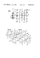
- FIG. 1 is a diagrammatic illustration of a gear mechanism with torque compensation in accordance with the invention
- FIGS. 2A and 2B diagrammatically illustrate torque compensation by pivoting of the drive shaft, FIG. 2A being without torque compensation; and FIG. 2B being with torque compensation;
- FIG. 3 is an axial section of an embodiment of a torque compensation system in the region of the drive shaft and the drive gear;
- FIG. 4 shows a detail section of FIG. 3 with two possible drive gears on the drive shaft
- FIG. 5 shows a detail section from FIG. 3 with a possible drive gear on the drive shaft and on the main or output shaft respectively.
- FIG. 1 shows a mechanism 1 having a clutch 2, wherein the driving torque is transmitted from the engine shaft 7 via the clutch 2 to the drive shaft 3.
- the drive gear 4 distributes the driving torque to the load-splitting gears 61 of the countershafts 6 and via the load-combining gears 62 and the output gear 53 the torque is again combined at the main shaft/output shaft.
- the input shaft 3 is only supported on the housing 11 via the axial bearing 31.
- the main/output shaft is dual mounted on the housing 11.
- the comparatively different manufacturing variations lead to a tooth spacing f between the teeth 410 of the drive gear 4 and the teeth 610 of the gear on the countershaft if no torque compensation is possible.
- the entire driving torque is therefore transmitted via the teeth 410', 610' and the other countershaft 6' to the teeth 620°, 530° and therefore to the output shaft 5.
- the teeth 410, 610 and 620 and 530 and the countershaft 6 do not take any part in the torque transmission.
- the drive shaft 3 may be pivoted and may therefore freely set the drive gear 4 on the countershafts under the action of the driving torque between the teeth 610" of the drive gears 61.
- the torque is therefore uniformly transmitted to the two gears 61.
- the outward pivot of the drive shaft 3 in this respect is a half of f so that the complete load compensation is obtained with a relatively small pivoting movement of the drive shaft.
- FIG. 3 shows a change-speed gear 10 with a clutch 2, wherein the region of the torque compensation is shown in detail and the remaining parts in diagrammatic form.
- the torque is transmitted via the engine output shaft 7 to the flywheel 21 of the clutch. If the clutch 2 is closed the clutch disc 26 is positively connected to the flywheel 21 and the torque is transmitted to the boss 25 and via the spline shaft coupling 24, 33 to the output shaft 3' with which the drive gear 4' for example is rigidly connected.
- the drive shaft 3' is connected at the journal 32 to the flywheel 21 of the clutch 2 via a radial bearing 22. Mounting in the gear housing 11 is carried out via an axial bearing 31.
- the drive shaft 3' may perform a pivoting movement and the drive gear 4' may be completely freely adjusted under the action of the torque between the gears 61 on the countershafts 6. This is obtained:
- all the gears for the forward movement area, predominantly in the torque compensation area, may be helically toothed, as better running characteristics and reduced running noise are obtained in this way.
- the axial forces from the helical toothing of the drive gear 4' must however be supported by an axial bearing (bearing 31) preferably between the drive shaft 3' and the gear housing 11.
- the axial bearing 31 enables easy pivoting of the drive shaft 3' which may be provided in one piece.
- the drive shaft 3' may be directly connected with the output shaft 5 via the switching clutch 8 so that the problem of torque compensation does not arise with this connection.
- FIGS. 4 and 5 illustrate the use of the invention in a modern change-speed gear, wherein the power division may take place in two different transmissions--i.e. with two different drive gears 41, 41' on the drive shaft 3" (FIG. 4) or one drive gear 43 on the drive shaft 3'" and one drive gear 51 on the output/main shaft 5 (FIG. 5).
- the sliding sleeve support 81, 81' is rigid with or connected in a rotationally and axially fixed manner with the input shaft 3", 3"'.
- the respective first drive gear 41, 43 is also mounted on the drive shaft 3", 3"', and the axial bearing 31', 31" for the drive shaft 3", 3"' is disposed such that the first drive gear 41, 43 is also axially supported on the housing 11 and performs the pivoting movement together with the drive shaft 3", 3"'.
- the second drive gear 41' is disposed in a rotatable, axially fixed and radially displaceable manner on a second journal 34 of the drive shaft 3", wherein an axial bearing 42 ensures easy movement with respect to rotation and radial displacements.
- the second drive gear 51 is disposed in a rotatable, axially fixed and radial displaceable manner on a journal 54 of the output/main shaft 5", wherein an axial bearing 52 ensures easy movement with respect to rotation and radial displacements.
- both drive gears 41, 41' are disposed on the drive shaft 3"
- the torque may then be uniformly distributed from both drive gears to the gears of the countershafts as a result of the features described above relating to the load compensation.
- the second drive gear 41' may be connected via a second switching clutch (not shown) to the output/main shaft.
- the axial bearing 42 between the drive shaft 3" and the second drive gear 41' enables comparatively reliable load compensation of the first drive gear 41 as a result of the unhindered pivotability of the drive shaft.
- This embodiment is further advantageous in particular as in the case of loading there is only a relative speed for the bearing 42 and the switched gears may not have any effect on this relative speed.
- the second drive gear 51 may also be connected to the output/main shaft 5 via a second switching clutch (not shown) and has no effect on the pivoting movement of the drive shaft 3'" with the first drive gear 43 as a result of its mounting on the output/main shaft (journal 54).
- the axial bearings (31, 31', 31", 42, 52) are not limited to the embodiments shown in FIGS. 3 to 5, but may also be embodied for example as slide or ball bearings.
Landscapes
- Engineering & Computer Science (AREA)
- General Engineering & Computer Science (AREA)
- Mechanical Engineering (AREA)
- Structure Of Transmissions (AREA)
- Gear Transmission (AREA)
Applications Claiming Priority (2)
| Application Number | Priority Date | Filing Date | Title |
|---|---|---|---|
| DE3049101A DE3049101C2 (de) | 1980-12-24 | 1980-12-24 | Zahnräderwechselgetriebe mit Leistungsteilung |
| DE3049101 | 1980-12-24 |
Publications (1)
| Publication Number | Publication Date |
|---|---|
| US4458546A true US4458546A (en) | 1984-07-10 |
Family
ID=6120333
Family Applications (1)
| Application Number | Title | Priority Date | Filing Date |
|---|---|---|---|
| US06/331,227 Expired - Fee Related US4458546A (en) | 1980-12-24 | 1981-12-16 | Gear mechanism |
Country Status (7)
| Country | Link |
|---|---|
| US (1) | US4458546A (enExample) |
| AU (1) | AU7846581A (enExample) |
| CA (1) | CA1178458A (enExample) |
| DE (1) | DE3049101C2 (enExample) |
| FR (1) | FR2496813A1 (enExample) |
| GB (1) | GB2089928B (enExample) |
| SE (1) | SE8107686L (enExample) |
Cited By (4)
| Publication number | Priority date | Publication date | Assignee | Title |
|---|---|---|---|---|
| US4730788A (en) * | 1985-09-13 | 1988-03-15 | Sundstrand Corporation | Reaction coupled, torque balanced geartrain |
| US5921137A (en) * | 1996-08-19 | 1999-07-13 | Zf Friedrichshafen Ag | Axial support for vehicle gearboxes with helical gear |
| US6658955B1 (en) * | 1999-06-15 | 2003-12-09 | Zf Friedrichshafen Ag | Gearwheel bearing in gearboxes |
| US20080188347A1 (en) * | 2006-11-09 | 2008-08-07 | Magneti Marelli Powertrain S.P.A. | Method for controlling a power assisted propulsion system in a motor vehicle |
Families Citing this family (5)
| Publication number | Priority date | Publication date | Assignee | Title |
|---|---|---|---|---|
| DE4329495A1 (de) * | 1993-09-01 | 1995-03-02 | Rostock Dieselmotoren | Koaxialgetriebe mit 3 Nebenwellen |
| DE19630803A1 (de) * | 1996-07-31 | 1998-02-05 | Zahnradfabrik Friedrichshafen | Wellenlagerung eines Getriebes mit mehreren Vorgelegewellen |
| DE19630804A1 (de) * | 1996-07-31 | 1998-02-05 | Zahnradfabrik Friedrichshafen | Schwenkbare Abstützung eines Zahnrades in Getrieben mit mehreren Vorgelegewellen |
| DE19631063A1 (de) * | 1996-08-01 | 1998-02-05 | Zahnradfabrik Friedrichshafen | Axiallagerung für Fahrzeuggetriebe mit Schrägverzahnung |
| DE19829925A1 (de) * | 1998-07-04 | 2000-01-05 | Zahnradfabrik Friedrichshafen | Zahnräderwechselgetriebe |
Citations (17)
| Publication number | Priority date | Publication date | Assignee | Title |
|---|---|---|---|---|
| DE380178C (de) * | 1919-05-10 | 1923-09-03 | Bbc Brown Boveri & Cie | Zahnraedergetriebe |
| US2014138A (en) * | 1933-06-30 | 1935-09-10 | Farrel Birmingham Co Inc | Gear drive |
| DE1031075B (de) * | 1953-03-18 | 1958-05-29 | Tacke Maschinenfabrik K G F | Drehmomentausgleich fuer Zweiweggetriebe |
| US2982144A (en) * | 1958-04-21 | 1961-05-02 | Wallgren August Gunn Ferdinand | Gearing |
| US3105395A (en) * | 1962-12-26 | 1963-10-01 | Eaton Mfg Co | Automotive device |
| US3138965A (en) * | 1961-08-31 | 1964-06-30 | Eaton Mfg Co | Change speed transmission |
| US3283613A (en) * | 1964-04-20 | 1966-11-08 | Eaton Yale & Towne | Automotive device |
| US3425290A (en) * | 1968-05-09 | 1969-02-04 | Eaton Yale & Towne | Twin countershaft construction with all main gears mounted concentrically on main shaft |
| US3500695A (en) * | 1968-08-23 | 1970-03-17 | Eaton Yale & Towne | Twin countershaft transmission in which the main shaft has one end floating and the other end pivoted |
| US3611823A (en) * | 1969-07-22 | 1971-10-12 | Eaton Yale & Towne | Floating main drive gear assembly |
| DE2419673A1 (de) * | 1973-04-24 | 1974-11-14 | Eric Alexander Pengilly | Zahnraederwechselgetriebe mit mehreren vorgelegewellen und lastausgleich |
| US3910131A (en) * | 1974-03-20 | 1975-10-07 | Eaton Corp | Transmission with snap shift |
| US4065981A (en) * | 1970-06-05 | 1978-01-03 | David Brown Gear Industries Limited | Gearing |
| US4104928A (en) * | 1976-09-20 | 1978-08-08 | Eaton Corporation | Transmission |
| US4106358A (en) * | 1972-03-17 | 1978-08-15 | Turner Manufacturing Company, Ltd. | Gear boxes |
| US4226135A (en) * | 1977-08-16 | 1980-10-07 | Zahnradfabrik Friedrichshafen Aktiengesellschaft | Load-splitting transmission |
| US4344517A (en) * | 1979-08-24 | 1982-08-17 | Nippon Seiko Kabushiki Kaisha | Clutch release device |
Family Cites Families (5)
| Publication number | Priority date | Publication date | Assignee | Title |
|---|---|---|---|---|
| DE1284238B (de) * | 1961-11-27 | 1968-11-28 | Demag Ag | Zweiweggetriebe |
| DE1171227B (de) * | 1962-01-12 | 1964-05-27 | Leipzig Getriebewerke | Planetengetriebe mit Selbsteinstellung des inneren und des aeusseren Zentralrades |
| FR1423682A (fr) * | 1964-07-16 | 1966-01-07 | Ceskoslovenska Akademie Ved | Mécanisme différentiel planétaire avec satellites doubles |
| BE757190A (fr) * | 1969-10-21 | 1971-03-16 | Karlstad Mekaniska Ab | Mecanisme de commande pour cylindre |
| DE2819293C3 (de) * | 1978-05-02 | 1981-11-12 | Zahnradfabrik Friedrichshafen Ag, 7990 Friedrichshafen | Zahnräderwechselgetriebe mit zwei Vorgelegewellen |
-
1980
- 1980-12-24 DE DE3049101A patent/DE3049101C2/de not_active Expired
-
1981
- 1981-11-05 CA CA000389555A patent/CA1178458A/en not_active Expired
- 1981-11-18 GB GB8134715A patent/GB2089928B/en not_active Expired
- 1981-12-01 FR FR8122509A patent/FR2496813A1/fr active Granted
- 1981-12-11 AU AU78465/81A patent/AU7846581A/en not_active Abandoned
- 1981-12-16 US US06/331,227 patent/US4458546A/en not_active Expired - Fee Related
- 1981-12-21 SE SE8107686A patent/SE8107686L/ not_active Application Discontinuation
Patent Citations (17)
| Publication number | Priority date | Publication date | Assignee | Title |
|---|---|---|---|---|
| DE380178C (de) * | 1919-05-10 | 1923-09-03 | Bbc Brown Boveri & Cie | Zahnraedergetriebe |
| US2014138A (en) * | 1933-06-30 | 1935-09-10 | Farrel Birmingham Co Inc | Gear drive |
| DE1031075B (de) * | 1953-03-18 | 1958-05-29 | Tacke Maschinenfabrik K G F | Drehmomentausgleich fuer Zweiweggetriebe |
| US2982144A (en) * | 1958-04-21 | 1961-05-02 | Wallgren August Gunn Ferdinand | Gearing |
| US3138965A (en) * | 1961-08-31 | 1964-06-30 | Eaton Mfg Co | Change speed transmission |
| US3105395A (en) * | 1962-12-26 | 1963-10-01 | Eaton Mfg Co | Automotive device |
| US3283613A (en) * | 1964-04-20 | 1966-11-08 | Eaton Yale & Towne | Automotive device |
| US3425290A (en) * | 1968-05-09 | 1969-02-04 | Eaton Yale & Towne | Twin countershaft construction with all main gears mounted concentrically on main shaft |
| US3500695A (en) * | 1968-08-23 | 1970-03-17 | Eaton Yale & Towne | Twin countershaft transmission in which the main shaft has one end floating and the other end pivoted |
| US3611823A (en) * | 1969-07-22 | 1971-10-12 | Eaton Yale & Towne | Floating main drive gear assembly |
| US4065981A (en) * | 1970-06-05 | 1978-01-03 | David Brown Gear Industries Limited | Gearing |
| US4106358A (en) * | 1972-03-17 | 1978-08-15 | Turner Manufacturing Company, Ltd. | Gear boxes |
| DE2419673A1 (de) * | 1973-04-24 | 1974-11-14 | Eric Alexander Pengilly | Zahnraederwechselgetriebe mit mehreren vorgelegewellen und lastausgleich |
| US3910131A (en) * | 1974-03-20 | 1975-10-07 | Eaton Corp | Transmission with snap shift |
| US4104928A (en) * | 1976-09-20 | 1978-08-08 | Eaton Corporation | Transmission |
| US4226135A (en) * | 1977-08-16 | 1980-10-07 | Zahnradfabrik Friedrichshafen Aktiengesellschaft | Load-splitting transmission |
| US4344517A (en) * | 1979-08-24 | 1982-08-17 | Nippon Seiko Kabushiki Kaisha | Clutch release device |
Cited By (6)
| Publication number | Priority date | Publication date | Assignee | Title |
|---|---|---|---|---|
| US4730788A (en) * | 1985-09-13 | 1988-03-15 | Sundstrand Corporation | Reaction coupled, torque balanced geartrain |
| US5921137A (en) * | 1996-08-19 | 1999-07-13 | Zf Friedrichshafen Ag | Axial support for vehicle gearboxes with helical gear |
| US6658955B1 (en) * | 1999-06-15 | 2003-12-09 | Zf Friedrichshafen Ag | Gearwheel bearing in gearboxes |
| US20080188347A1 (en) * | 2006-11-09 | 2008-08-07 | Magneti Marelli Powertrain S.P.A. | Method for controlling a power assisted propulsion system in a motor vehicle |
| US7967725B2 (en) * | 2006-11-09 | 2011-06-28 | Magneti Marelli Powertrain S.P.A. | Method for controlling a power assisted propulsion system in a motor vehicle |
| CN101201106B (zh) * | 2006-11-09 | 2013-01-09 | 玛涅蒂玛瑞利动力系统股份有限公司 | 用于控制汽车中的助力动力传动系的方法 |
Also Published As
| Publication number | Publication date |
|---|---|
| SE8107686L (sv) | 1982-06-25 |
| CA1178458A (en) | 1984-11-27 |
| GB2089928B (en) | 1985-01-03 |
| DE3049101C2 (de) | 1983-10-13 |
| FR2496813A1 (fr) | 1982-06-25 |
| DE3049101A1 (de) | 1982-07-01 |
| AU7846581A (en) | 1982-07-01 |
| GB2089928A (en) | 1982-06-30 |
| FR2496813B1 (enExample) | 1985-03-15 |
Similar Documents
| Publication | Publication Date | Title |
|---|---|---|
| US4317389A (en) | Vehicle drive transmission system | |
| US5588328A (en) | Gear mechanism improved to remove backlash | |
| US5372052A (en) | Motor vehicle change-speed gearbox shaft bearing arrangement | |
| US4388838A (en) | Multiple countershaft simple transmission | |
| US4136580A (en) | Power branching transmission | |
| US4458546A (en) | Gear mechanism | |
| EP0851149B1 (en) | A planetary gear mechanism | |
| GB1591973A (en) | Extended range transmission | |
| US4353269A (en) | Ship's transmission with changeover from cruising speed to slow speed | |
| EP1155248B1 (en) | Bearing support for infinitely-variable-ratio transmission output discs | |
| JPH034783B2 (enExample) | ||
| US4709590A (en) | Herringbone geared multiple load sharing countershaft transmission | |
| GB2054774A (en) | Steplessly variable epicyclic gearing | |
| US5921137A (en) | Axial support for vehicle gearboxes with helical gear | |
| US4269077A (en) | Change gear transmission | |
| US5284067A (en) | Manual transmission shaft center control support device | |
| WO1986007423A1 (en) | Reversing gear mechanism | |
| US5517874A (en) | Motor vehicle gearbox with brake means in countershaft and unequal gear teeth on gears of dual countershafts | |
| US4957460A (en) | Thrust bearing arrangement for marine outboard drives | |
| US4610174A (en) | Transmission for a tractor | |
| EP0299930B1 (en) | Motor vehicle gearbox with a device for synchronised engagement of reverse | |
| US4550629A (en) | Continuously variable speed transmission for motor vehicles | |
| US4466303A (en) | Infinitely variable friction-cone transmission with movable flange-mounted motor | |
| JPS6331822A (ja) | 自動変速機を備えた車両の終減速機装置 | |
| US7669494B2 (en) | Gear box with two pinion shafts |
Legal Events
| Date | Code | Title | Description |
|---|---|---|---|
| AS | Assignment |
Owner name: ZAHNRADFABRIK FRIEDRICHSHAFEN AG., FRIEDRICHSHAFEN Free format text: ASSIGNMENT OF ASSIGNORS INTEREST.;ASSIGNORS:SCHREINER, FRIEDRICH;STABEROH, UWE;REEL/FRAME:003969/0150 Effective date: 19811023 |
|
| REMI | Maintenance fee reminder mailed | ||
| LAPS | Lapse for failure to pay maintenance fees | ||
| STCH | Information on status: patent discontinuation |
Free format text: PATENT EXPIRED DUE TO NONPAYMENT OF MAINTENANCE FEES UNDER 37 CFR 1.362 |
|
| FP | Lapsed due to failure to pay maintenance fee |
Effective date: 19880710 |