US4436393A - Distortion correction for an overhead projector system - Google Patents
Distortion correction for an overhead projector system Download PDFInfo
- Publication number
- US4436393A US4436393A US06/455,425 US45542583A US4436393A US 4436393 A US4436393 A US 4436393A US 45542583 A US45542583 A US 45542583A US 4436393 A US4436393 A US 4436393A
- Authority
- US
- United States
- Prior art keywords
- projection
- lens
- stage
- optic axis
- projection lens
- Prior art date
- Legal status (The legal status is an assumption and is not a legal conclusion. Google has not performed a legal analysis and makes no representation as to the accuracy of the status listed.)
- Expired - Fee Related
Links
Images


Classifications
-
- G—PHYSICS
- G03—PHOTOGRAPHY; CINEMATOGRAPHY; ANALOGOUS TECHNIQUES USING WAVES OTHER THAN OPTICAL WAVES; ELECTROGRAPHY; HOLOGRAPHY
- G03B—APPARATUS OR ARRANGEMENTS FOR TAKING PHOTOGRAPHS OR FOR PROJECTING OR VIEWING THEM; APPARATUS OR ARRANGEMENTS EMPLOYING ANALOGOUS TECHNIQUES USING WAVES OTHER THAN OPTICAL WAVES; ACCESSORIES THEREFOR
- G03B21/00—Projectors or projection-type viewers; Accessories therefor
- G03B21/132—Overhead projectors, i.e. capable of projecting hand-writing or drawing during action
-
- Y—GENERAL TAGGING OF NEW TECHNOLOGICAL DEVELOPMENTS; GENERAL TAGGING OF CROSS-SECTIONAL TECHNOLOGIES SPANNING OVER SEVERAL SECTIONS OF THE IPC; TECHNICAL SUBJECTS COVERED BY FORMER USPC CROSS-REFERENCE ART COLLECTIONS [XRACs] AND DIGESTS
- Y10—TECHNICAL SUBJECTS COVERED BY FORMER USPC
- Y10S—TECHNICAL SUBJECTS COVERED BY FORMER USPC CROSS-REFERENCE ART COLLECTIONS [XRACs] AND DIGESTS
- Y10S353/00—Optics: image projectors
- Y10S353/03—Transparent
Definitions
- This invention relates to overhead projectors and, more specifically, to an improved system of overhead projection which forms an undistorted image on a vertical surface or screen.
- Conventional overhead projectors include a stage which supports the transparency to be projected, lighting means mounted below the stage to illuminate the transparency, and a projection lens and mirror combination suspended above the stage to direct the light image of the transparency onto a viewing screen. If the stage and projection lens are in parallel planes; the centers of the projection lens, the stage and the light source are on a common axis; and the mirror is oriented at a 45° angle to the plane of the stage, an undistorted image will be projected on a vertical screen. However, if these conditions are met, at least half of the projected image will be below the level of the mirror and, consequently, the audience's view of the image will be obstructed by the projector.
- the mirror is commonly tilted to an angle greater than 45° with respect to the horizontal, thereby raising the projected image above the level of the projector. If the viewing screen remains vertical, this projection of the image at an oblique angle above the horizontal results in a magnification distortion of the image into a trapezoidal shape in which the upper portion of the image is wider than the lower portion. Because of the shape of the projected image, this magnification distortion is commonly referred to as "keystoning".
- a second type of distortion common to such projectors is a lack of uniform focus throughout the projected image. This type of distortion will occur unless the so-called Scheimpflug condition is met which requires that the plane of the screen and the planes of the virtual images of the projection lens and the stage be parallel or converge to a common point.
- oblique projection of the image may be achieved without introducing either keystone distortion or focus non-uniformity distortion by tilting some of the elements which comprise the projector.
- U.S. Pat. No. 4,002,408 which issued to Amma on Jan. 11, 1977, for example, discloses two methods by which it is claimed that distortion-free oblique projection may be achieved. The first method involves moving the projection lens and mirror away from the center of the stage toward the screen and tilting the lighting means to project light at an angle through the transparency to the projection lens and mirror.
- the second method requires that the projection lens and the stage be tilted with respect to the mirror and the illuminating apparatus. Both methods introduce mechanical complexities to the projector and a tilted stage would pose difficulties for the presenter in positioning the transparency on the stage and writing on the transparency as it is being projected.
- An overhead projector is able, by purely optical means, i.e without tilting any of the components of the system, to project a uniformly focused image onto a vertical screen at an oblique angle above the horizontal plane without introducing keystone distortion.
- the foregoing is accomplished by offsetting a projection lens and its associated mirror from the center of a transparency stage of the overhead projector in the direction of projection and directing light through the transparency and to the projection lens at an angle which is equal to the oblique angle above the horizontal plane at which the image is projected.
- Light is directed to the projection lens by offsetting the upper lens of a two-element annular Fresnel condensing lens system in the direction of displacement of the projection lens.
- FIGS. 1A and 1B illustrate a prior art system of overhead projection by way of clarification of the principles of this invention
- 1A being a schematic side view of the prior system
- 1B being an elevational view of a screen and an image projected on the screen
- FIGS. 2A and 2B illustrate the effect of oblique projection on the image projected by the system of FIGS. 1A and 1B;
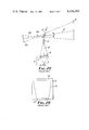
- FIGS. 3A and 3B illustrate a projection system according to the present invention
- 3A being a schematic side view of the projection system
- 3B being an elevational view of a projection screen and an image projected on the screen
- FIG. 4 is an enlarged schematic side view of condensing lens elements of the projection system of FIG. 3A in cross-section.
- FIGS. 1A and 1B of the accompanying drawings a lamp 2 of suitable and conventional type is provided above a concave reflector 4, while a condensing lens system 6, which may be an annular Fresnel lens or a combination of annular Fresnel lenses, is mounted above the lamp 2 so that light emitted by the lamp 2 and the reflector 4 is collected by the condensing lens system 6 centered over the light source and is focused above the lens system 6. All these elements constitute, in combination, lighting means generally indicated by the numeral 8.
- a transparent stage 10 upon which is placed a transparency or slide (not shown) to be imaged.
- the transparency or slide is hereinafter simply referred to as a "transparency" to mean any such picture or light-transmissive material adapted for projection in an overhead projector.
- a projection lens 12 often consisting of two positive lenses and a single negative lens, is mounted further above the stage 10 along the optic axis of the condensing lens system 6, and a mirror 14 is suitably mounted to intercept light from the projection lens 12 and project an image onto a vertical screen 16.
- the mirror 14 is oriented at a 45° angle to the horizontal plane so the optic axis 18 of the projected image 20 is perpendicular to the stage 10 and the screen 16.
- the plane of the virtual image of the stage 10a and the plane of the screen 16 are parallel. Since the planes of the virtual image of the stage 10a and the screen 16 are parallel, no magnification distortion of the image 20 will occur. Also, since the planes of the virtual images of the stage 10a and the projection lens 12a, and the plane of the screen 16, are parallel, uniform focus will be achieved throughout the image 20 because the Scheimpflug condition is met.
- the Scheimpflug condition requires that for the image 20 to be uniformly in focus, the planes of the virtual images of the stage 10a and the projection lens 12a and the plane of the screen 16 must be either parallel or converge to a common point.
- the optic axis 18 of the system be projected perpendicularly to the screen 16 by orienting the mirror 14 at a 45° angle to the horizontal plane.
- This configuration is undesirable because at least a portion of the image 20 will be obscured because the overhead projector 1 is located between the screen 16 and the audience.
- FIGS. 3A and 3B illustrate a projection system 27 and an image projected according to the present invention in which the image is projected at an oblique angle above the horizontal plane without producing either of the distortions discussed above, i.e., magnification distortion or focus non-uniformity.
- a projection lens 28 is offset from the center of a stage 30 toward a projection screen 32, i.e., in the direction of projection, and the associated mirror 33 is oriented at 45° to a horizontal plane so that the optic axis 34 extends from the stage 30 to the projection lens 28 at an angle " ⁇ " equal to the oblique projection angle of the image above the horizontal plane.
- Magnification distortion or "keystoning" is not introduced because, as shown in FIG. 3A, the plane of the virtual image of the stage 30a is parallel to the plane of the screen 32. Focus uniformity is maintained throughout the image 36, shown in FIG. 3B, because the projection lens 28 is translated and not rotated with respect to the stage 30.
- the Scheimpflug condition is satisfied because the plane of the virtual image of the projection lens 28a is parallel to the plane of the virtual image of the stage 30a and the plane of the screen 32.
- the foregoing inclination of the optic axis 34 is accomplished by off-setting the center 38 of an upper annular Fresnel lens 40 with respect to the center 42 of a lower annular Fresnel lens 44 and the optic axis 46 of a lamp 48 and reflector 50.
- the upper Fresnel lens 40 and the lower Fresnel lens 44 constitute in combination a condensing lens system 52 which corresponds to the condensing lens system 6 of FIGS. 1A and 2A, and the lamp 48 and the reflector 50 correspond to the lamp 2 and reflector 4 of FIGS. 1A and 2A.
- the combination of the condensing lens system 52, lamp 48, and reflector 50 constitute a lighting means 54 which corresponds to the lighting means 8 of FIGS. 1A and 2A.
- the angle " ⁇ " at which an image 36 may be projected free of magnification distortion and distortion due to focus non-uniformity may be varied over a range of values by providing an upper Fresnel lens 40 which is considerably larger, as indicated by phantom lines 56, than the lower Fresnel lens 44 and the stage 30.
- Such a lens 40 would permit the projection offset angle " ⁇ " to be adjusted by allowing the relative offset of the center 38 of the upper Fresnel lens 40 with respect to the center 42 of the lower Fresnel lens 44, and thus the inclination of the optic axis 34, to be varied.
- the projection lens 28 must be repositioned to intercept the optic axis 34 of light exiting the stage 30.
- the parameters of the lenses 28, 40, and 44 and the dimensions of the projector 27 are selected such that the projection lens 28 will be properly positioned when it is directly over the center 38 of the upper Fresnel lens 40. This relationship between the center 38 of the Fresnel lens 40 and the projection lens 28 is not required for distortion-free projection, however.
- the projection lens 28 and the upper Fresnel lens 40 be offset from the center 42 of the lower Fresnel lens 44 (and the center of the stage 30) in a common direction and that the projection lens 28 be positioned along the optic axis 34 of the light exiting the upper Fresnel lens 40.
- the angle " ⁇ " will be equal to zero and distortion-free projection can only be achieved in the horizontal plane. This condition corresponds to the projection configuration shown in FIG. 1A.
- the maximum oblique projection angle is limited to approximately 15°, because of the construction and parameters of the Fresnel lens 40, and the usable field angle of the projection lens 28.
- the projection lens 28 and the upper Fresnel lens 40 could be connected together and moved simultaneously by a convenient mechanical linkage.
- the projection lens 28 and the upper Fresnel lens 40 could be manually positioned by means of suitable horizontal carriages which may or may not be interconnected.
- a large upper Fresnel lens 40 could be used to provide a range of oblique projection angles " ⁇ " at which distortion-free projection may be achieved. If it were desired to limit the oblique projection angle to a single value, however, the upper Fresnel lens 40 could be cropped to dimensions which correspond to the lower Fresnel lens 44 and the stage 30.
- a specific example of an overhead projector 27 according to the present invention which is designed to project an undistorted image at a predetermined oblique angle above the horizontal plane onto a vertical screen includes two annular Fresnel lenses 40 and 44 which are manufactured of clear acrylic plastic, with a refractive index of 1.491 for yellow light.
- the width of the individual grooves formed in the surfaces of the lenses 40 and 44 is between 0.010 and 0.020 inches (0.25 and 0.51 mm) and the thickness of each lens 40 or 44 is between 0.050 and 0.100 inches (1.27 and 2.5 mm).
- the lower Fresnel lens 44 has a focal length of 12.6 inches (320 mm) and the upper Fresnel lens has a focal length of 16.7 inches (424 mm) to yield a combined focal length of 7.2 inches (183 mm).
- the two Fresnel lenses 40 and 44 are located directly below the stage 30 which is clear glass and has lateral dimensions of 11.2 inches (284 mm) by 11.2 inches (284 mm).
- the lamp 48 is located 12.6 inches (320 mm) below the lower Fresnel lens 44.
- Above the stage 30 is located the projection lens 28 which has a focal length of 12.9 inches (328 mm) and a back focus of 14.4 inches (366 mm).
- the center of the projection lens 28 is vertically spaced from the stage 30 a distance of 15.2 inches (386 mm) to operate at a 5.4X magnification.
- Both the projection lens 28 and the center 38 of the upper Fresnel lens 40 are horizontally offset from the center 42 of the lower Fresnel lens 44 a distance of 3.25 inches (83 mm).
- An overhead projector 27 constructed in such a fashion will project a distortion-free image at an oblique angle " ⁇ " above the horizontal plane of 12°, an angle which has been determined to provide comfortable viewing for the audience.
- the projection lens 28 and the upper Fresnel lens 40 are offset an equal distance from the center 42 of the lower Fresnel 44 and the optic axis of the lamp 48 and reflector 50. This is because the parameters of the various elements and the distances between elements are selected so that light traveling from the lower Fresnel lens 44 to the upper Fresnel lens 40 is collimated or parallel.
- the lamp 48 is located one focal length (12.6 inches or 320 mm) from the lower Fresnel 44 and the center of the projection lens 28 is located one focal length (16.7 inches or 424 mm) from the upper Fresnel lens 40.
- Collimated light from the lower Fresnel lens 44 is not a requirement of the projection system described above, but rather is merely a convenient basis around which to design the system. If light exiting the lower Fresnel lens 44 is to be collimated, then it will so happen that the offset of the projection lens 28 and the offset of the center 38 of the upper Fresnel lens 40 will be equal. If light exiting the lower Fresnel lens 44 is divergent or convergent, the offset of the projection lens 28 will be different from the offset of the upper Fresnel lens 40, but will always be in the same direction and the projection lens 28 will always be positioned along the optic axis 34 of the light exiting the upper Fresnel lens 40.
- the projection lens 28 will have to be moved vertically toward or away from the stage 30, always along the inclined optic axis 34.
- Fresnel lenses are usually non-achromatic, longer wavelength light rays cross the projection lens focusing (horizontal) axis at a greater distance than the shorter wavelength light rays.
- a remarkable property of offsetting the upper Fresnel lens 40 is that the image of the lamp 48 always moves along the optic axis 34 of light exiting the upper Fresnel lens 40 as the lamp 48 moves along the fixed light axis 46 always perpendicular to the plane of the lower Fresnel lens 44.
- the projected image can be "color tuned” merely by moving the lamp 48 perpendicularly toward or away from the lower Fresnel lens 44. This movement of the lamp 48 ensures that the transparency will always be symmetrically illuminated. It will be apparent to those skilled in the art that a simple mechanical connection between the projection lens 28 and the lamp 48 could be provided to coordinate the movement of these two elements and provide automatic "color tuning" of the system in response to projection lens 28 movement.
- Moire interference patterns are produced which appear as a series of intense radial lines which increase in number as the separation of the centers of the lenses increases. These patterns are projected along with the transparency image and, hence, are undesirable.
- This effect can be reduced considerably by selecting different groove frequencies for the upper Fresnel lens 40 and the lower Fresnel lens 44. If the ratio of the groove frequencies of the two Fresnel lenses 40 and 44 is in the range of 1.3 to 1.5, the intensity of the Moire interference patterns is significantly reduced. Specifically, when the groove frequency of the lower Fresnel lens 44 is 3.94 grooves per millimeter, and the groove frequency of the upper Fresnel lens 40 is 2.78 groves per millimeter, the interference pattern is reduced to a very low intensity which is hardly noticeable.
Landscapes
- Physics & Mathematics (AREA)
- General Physics & Mathematics (AREA)
- Overhead Projectors And Projection Screens (AREA)
- Projection Apparatus (AREA)
Priority Applications (9)
| Application Number | Priority Date | Filing Date | Title |
|---|---|---|---|
| US06/455,425 US4436393A (en) | 1983-01-03 | 1983-01-03 | Distortion correction for an overhead projector system |
| CA000442933A CA1240542A (en) | 1983-01-03 | 1983-12-09 | Distortion correction for an overhead projector system |
| JP58244972A JPS59136726A (ja) | 1983-01-03 | 1983-12-27 | オ−バヘツドプロジエクタ |
| KR1019830006347A KR890001175B1 (ko) | 1983-01-03 | 1983-12-30 | 오버 헤드 프로젝터 |
| KR1019830006350A KR890000458B1 (ko) | 1983-01-03 | 1983-12-30 | 오버헤드 프로젝타(overhead projector) |
| BR8400004A BR8400004A (pt) | 1983-01-03 | 1984-01-02 | Retroprojetor |
| EP84300006A EP0115901B1 (en) | 1983-01-03 | 1984-01-03 | Distortion correction for an overhead projector system |
| DE8484300006T DE3467428D1 (en) | 1983-01-03 | 1984-01-03 | Distortion correction for an overhead projector system |
| JP1992032992U JP2553427Y2 (ja) | 1983-01-03 | 1992-05-20 | オーバヘッドプロジェクタ |
Applications Claiming Priority (1)
| Application Number | Priority Date | Filing Date | Title |
|---|---|---|---|
| US06/455,425 US4436393A (en) | 1983-01-03 | 1983-01-03 | Distortion correction for an overhead projector system |
Publications (1)
| Publication Number | Publication Date |
|---|---|
| US4436393A true US4436393A (en) | 1984-03-13 |
Family
ID=23808752
Family Applications (1)
| Application Number | Title | Priority Date | Filing Date |
|---|---|---|---|
| US06/455,425 Expired - Fee Related US4436393A (en) | 1983-01-03 | 1983-01-03 | Distortion correction for an overhead projector system |
Country Status (7)
| Country | Link |
|---|---|
| US (1) | US4436393A (ko) |
| EP (1) | EP0115901B1 (ko) |
| JP (2) | JPS59136726A (ko) |
| KR (2) | KR890001175B1 (ko) |
| BR (1) | BR8400004A (ko) |
| CA (1) | CA1240542A (ko) |
| DE (1) | DE3467428D1 (ko) |
Cited By (22)
| Publication number | Priority date | Publication date | Assignee | Title |
|---|---|---|---|---|
| US4561740A (en) * | 1984-06-06 | 1985-12-31 | Minnesota Mining And Manufacturing Company | Dual-magnification rear projection lectern |
| US4824210A (en) * | 1985-02-21 | 1989-04-25 | Casio Computer Co., Ltd. | Liquid crystal projector |
| US4986651A (en) * | 1989-08-04 | 1991-01-22 | Minnesota Mining And Manufacturing Company | Overhead projector with centerless Fresnel lens reflective stage |
| US5032022A (en) * | 1988-09-14 | 1991-07-16 | Casio Computer Co., Ltd. | Projector |
| US5092672A (en) * | 1991-06-07 | 1992-03-03 | Minnesota Mining And Manufacturing Company | Condenser lens system for overhead projector |
| US5220363A (en) * | 1988-09-14 | 1993-06-15 | Casio Computer Co., Ltd. | Projector |
| US5296882A (en) * | 1992-12-21 | 1994-03-22 | Minnesota Mining And Manufacturing Company | Overhead projector with catadioptric fresnel lens |
| US5317349A (en) * | 1993-06-29 | 1994-05-31 | Minnesota Mining And Manufacturing Company | Overhead projector with achromatic fresnel lens |
| US5355188A (en) * | 1993-09-09 | 1994-10-11 | In Focus Systems, Inc. | Method and apparatus for distortion correction in optical projectors |
| US5400094A (en) * | 1993-03-31 | 1995-03-21 | Minnesota Mining And Manufacturing Company | Condensers for overhead projectors |
| US5416541A (en) * | 1994-05-16 | 1995-05-16 | Fog; Stephen C. | Folding portable overhead projector |
| US5548357A (en) * | 1995-06-06 | 1996-08-20 | Xerox Corporation | Keystoning and focus correction for an overhead projector |
| US5639152A (en) * | 1996-06-11 | 1997-06-17 | Telex Communications, Inc. | Collapsible LCD projector |
| US5722752A (en) * | 1997-01-10 | 1998-03-03 | In Focus Systems, Inc. | Multimedia projection system with image quality correction |
| US5820242A (en) * | 1996-03-29 | 1998-10-13 | Minnesota Mining And Manufacturing Company | Compact integrated LCD projector |
| WO1999010760A1 (de) * | 1997-08-26 | 1999-03-04 | Fresnel Optics Gmbh | Optische anordnung bestehend aus mindestens zwei fresnellinsen und deren verwendung |
| US6031608A (en) * | 1998-09-03 | 2000-02-29 | Foss Nirsystems, Inc. | Spectroscopic instrument with offset grating to improve focus |
| US6141000A (en) * | 1991-10-21 | 2000-10-31 | Smart Technologies Inc. | Projection display system with touch sensing on screen, computer assisted alignment correction and network conferencing |
| US6155686A (en) * | 1997-08-21 | 2000-12-05 | Seiko Epson Corporation | Projection display device |
| KR100333970B1 (ko) * | 1999-08-31 | 2002-04-24 | 구자홍 | 키스톤 제거기능을 가지는 투사 표시장치 |
| US20100006088A1 (en) * | 2008-07-14 | 2010-01-14 | Robert Owen Campbell | Tracking Concentrator Employing Inverted Off-Axis Optics and Method |
| US11885738B1 (en) | 2013-01-22 | 2024-01-30 | J.A. Woollam Co., Inc. | Reflectometer, spectrophotometer, ellipsometer or polarimeter system including sample imaging system that simultaneously meet the scheimpflug condition and overcomes keystone error |
Families Citing this family (4)
| Publication number | Priority date | Publication date | Assignee | Title |
|---|---|---|---|---|
| BE790926A (fr) * | 1971-11-05 | 1973-03-01 | Ifoeverken Ab | Dispositif en vue de raccorder le reservoir de chasse a la cuvette d'uncabinet d'aisances |
| JPH03209421A (ja) * | 1990-01-12 | 1991-09-12 | Victor Co Of Japan Ltd | 光―光変換素子の応用装置 |
| SE9300958L (sv) * | 1993-03-23 | 1994-09-24 | Nova Onab Optica Ab | Offset projektor |
| GB2343526A (en) * | 1998-11-04 | 2000-05-10 | Int Optics Limited | Objective arrangements for projectors |
Family Cites Families (5)
| Publication number | Priority date | Publication date | Assignee | Title |
|---|---|---|---|---|
| US3547530A (en) * | 1968-11-12 | 1970-12-15 | Bell Telephone Labor Inc | Overhead projector |
| JPS51933Y1 (ko) * | 1969-06-17 | 1976-01-12 | ||
| JPS5116755U (ko) * | 1974-07-24 | 1976-02-06 | ||
| DE2828245A1 (de) * | 1978-06-28 | 1980-01-03 | Rainer Wolfgang Landsee | Projektor |
| JPS5557840A (en) * | 1978-10-24 | 1980-04-30 | Gakken Co Ltd | Overhead projector capable of projecting on vertical plane |
-
1983
- 1983-01-03 US US06/455,425 patent/US4436393A/en not_active Expired - Fee Related
- 1983-12-09 CA CA000442933A patent/CA1240542A/en not_active Expired
- 1983-12-27 JP JP58244972A patent/JPS59136726A/ja active Pending
- 1983-12-30 KR KR1019830006347A patent/KR890001175B1/ko not_active IP Right Cessation
- 1983-12-30 KR KR1019830006350A patent/KR890000458B1/ko not_active IP Right Cessation
-
1984
- 1984-01-02 BR BR8400004A patent/BR8400004A/pt not_active IP Right Cessation
- 1984-01-03 DE DE8484300006T patent/DE3467428D1/de not_active Expired
- 1984-01-03 EP EP84300006A patent/EP0115901B1/en not_active Expired
-
1992
- 1992-05-20 JP JP1992032992U patent/JP2553427Y2/ja not_active Expired - Lifetime
Cited By (32)
| Publication number | Priority date | Publication date | Assignee | Title |
|---|---|---|---|---|
| EP0170370A1 (en) * | 1984-06-06 | 1986-02-05 | Minnesota Mining And Manufacturing Company | Dual-magnification rear projection lectern |
| US4561740A (en) * | 1984-06-06 | 1985-12-31 | Minnesota Mining And Manufacturing Company | Dual-magnification rear projection lectern |
| US4824210A (en) * | 1985-02-21 | 1989-04-25 | Casio Computer Co., Ltd. | Liquid crystal projector |
| US5302983A (en) * | 1988-09-14 | 1994-04-12 | Casio Computer Co., Ltd. | Projector |
| US5032022A (en) * | 1988-09-14 | 1991-07-16 | Casio Computer Co., Ltd. | Projector |
| US5220363A (en) * | 1988-09-14 | 1993-06-15 | Casio Computer Co., Ltd. | Projector |
| US4986651A (en) * | 1989-08-04 | 1991-01-22 | Minnesota Mining And Manufacturing Company | Overhead projector with centerless Fresnel lens reflective stage |
| US5092672A (en) * | 1991-06-07 | 1992-03-03 | Minnesota Mining And Manufacturing Company | Condenser lens system for overhead projector |
| US7626577B2 (en) | 1991-10-21 | 2009-12-01 | Smart Technologies Ulc | Projection display system with pressure sensing at a screen, a calibration system corrects for non-orthogonal projection errors |
| US6141000A (en) * | 1991-10-21 | 2000-10-31 | Smart Technologies Inc. | Projection display system with touch sensing on screen, computer assisted alignment correction and network conferencing |
| US20040263488A1 (en) * | 1991-10-21 | 2004-12-30 | Martin David A | Projection display system with pressure sensing at screen, and computer assisted alignment implemented by applying pressure at displayed calibration marks |
| US6337681B1 (en) | 1991-10-21 | 2002-01-08 | Smart Technologies Inc. | Projection display system with pressure sensing at screen, and computer assisted alignment implemented by applying pressure at displayed calibration marks |
| US7289113B2 (en) | 1991-10-21 | 2007-10-30 | Smart Technologies Inc. | Projection display system with pressure sensing at screen, and computer assisted alignment implemented by applying pressure at displayed calibration marks |
| US6747636B2 (en) | 1991-10-21 | 2004-06-08 | Smart Technologies, Inc. | Projection display and system with pressure sensing at screen, and computer assisted alignment implemented by applying pressure at displayed calibration marks |
| US20080042999A1 (en) * | 1991-10-21 | 2008-02-21 | Martin David A | Projection display system with pressure sensing at a screen, a calibration system corrects for non-orthogonal projection errors |
| US5568324A (en) * | 1992-12-21 | 1996-10-22 | Minnesota Mining And Manufacturing Company | Overhead projector with catadioptric fresnel lens |
| US5296882A (en) * | 1992-12-21 | 1994-03-22 | Minnesota Mining And Manufacturing Company | Overhead projector with catadioptric fresnel lens |
| US5400094A (en) * | 1993-03-31 | 1995-03-21 | Minnesota Mining And Manufacturing Company | Condensers for overhead projectors |
| US5317349A (en) * | 1993-06-29 | 1994-05-31 | Minnesota Mining And Manufacturing Company | Overhead projector with achromatic fresnel lens |
| US5355188A (en) * | 1993-09-09 | 1994-10-11 | In Focus Systems, Inc. | Method and apparatus for distortion correction in optical projectors |
| US5416541A (en) * | 1994-05-16 | 1995-05-16 | Fog; Stephen C. | Folding portable overhead projector |
| US5548357A (en) * | 1995-06-06 | 1996-08-20 | Xerox Corporation | Keystoning and focus correction for an overhead projector |
| US5820242A (en) * | 1996-03-29 | 1998-10-13 | Minnesota Mining And Manufacturing Company | Compact integrated LCD projector |
| US5639152A (en) * | 1996-06-11 | 1997-06-17 | Telex Communications, Inc. | Collapsible LCD projector |
| US5722752A (en) * | 1997-01-10 | 1998-03-03 | In Focus Systems, Inc. | Multimedia projection system with image quality correction |
| US6155686A (en) * | 1997-08-21 | 2000-12-05 | Seiko Epson Corporation | Projection display device |
| US6377406B1 (en) | 1997-08-26 | 2002-04-23 | Fresnel Optics, Inc. | Optical arrangement and the use thereof |
| WO1999010760A1 (de) * | 1997-08-26 | 1999-03-04 | Fresnel Optics Gmbh | Optische anordnung bestehend aus mindestens zwei fresnellinsen und deren verwendung |
| US6031608A (en) * | 1998-09-03 | 2000-02-29 | Foss Nirsystems, Inc. | Spectroscopic instrument with offset grating to improve focus |
| KR100333970B1 (ko) * | 1999-08-31 | 2002-04-24 | 구자홍 | 키스톤 제거기능을 가지는 투사 표시장치 |
| US20100006088A1 (en) * | 2008-07-14 | 2010-01-14 | Robert Owen Campbell | Tracking Concentrator Employing Inverted Off-Axis Optics and Method |
| US11885738B1 (en) | 2013-01-22 | 2024-01-30 | J.A. Woollam Co., Inc. | Reflectometer, spectrophotometer, ellipsometer or polarimeter system including sample imaging system that simultaneously meet the scheimpflug condition and overcomes keystone error |
Also Published As
| Publication number | Publication date |
|---|---|
| KR890001175B1 (ko) | 1989-04-26 |
| CA1240542A (en) | 1988-08-16 |
| EP0115901A1 (en) | 1984-08-15 |
| JPS59136726A (ja) | 1984-08-06 |
| JPH058555U (ja) | 1993-02-05 |
| JP2553427Y2 (ja) | 1997-11-05 |
| KR840007472A (ko) | 1984-12-07 |
| DE3467428D1 (en) | 1987-12-17 |
| BR8400004A (pt) | 1984-07-31 |
| KR840007473A (ko) | 1984-12-07 |
| EP0115901B1 (en) | 1987-11-11 |
| KR890000458B1 (ko) | 1989-03-17 |
Similar Documents
| Publication | Publication Date | Title |
|---|---|---|
| US4436393A (en) | Distortion correction for an overhead projector system | |
| US4436392A (en) | Distortion correction for an overhead projector system | |
| US4089599A (en) | Device for correcting distortion of a projected image | |
| KR890017486A (ko) | 조명 시스템 | |
| US4765733A (en) | Light projector | |
| EP0272807B1 (en) | Reduced height transmissive overhead projector | |
| CA2438290A1 (en) | Projection-type display apparatus | |
| US3944351A (en) | Apparatus for superimposing a plurality of images | |
| US5283602A (en) | Optical system for projector | |
| KR100808737B1 (ko) | 비디오프로젝터용 조명 광학 시스템 | |
| JP3480256B2 (ja) | 投影光学装置 | |
| US5092672A (en) | Condenser lens system for overhead projector | |
| US3915568A (en) | Overhead projector | |
| US4867555A (en) | Retrofocus lens for overhead projector | |
| US2466338A (en) | Skewed schmidt television projector with directive screen | |
| US5548373A (en) | Image reading apparatus | |
| US5331360A (en) | Adaptor for overhead projector | |
| US4974958A (en) | Projecting optical apparatus having no trapezoidal distortion | |
| JP3326373B2 (ja) | 投写装置 | |
| JPH04298730A (ja) | オーバーヘッド・プロジェクタ | |
| JPH0721587B2 (ja) | 投影機 | |
| JPH03180829A (ja) | 投写型プロジェクター | |
| JPH06160980A (ja) | オーバーヘッドプロジェクタおよびその光軸調整方法 | |
| JPS63188125A (ja) | 投影装置 | |
| JPH03212087A (ja) | 撮像装置 |
Legal Events
| Date | Code | Title | Description |
|---|---|---|---|
| AS | Assignment |
Owner name: MINNESOTA MINING AND MANUFACTURING COMPANY, ST. PA Free format text: ASSIGNMENT OF ASSIGNORS INTEREST.;ASSIGNOR:VANDERWERF, DENNIS F.;REEL/FRAME:004083/0870 Effective date: 19821230 |
|
| MAFP | Maintenance fee payment |
Free format text: PAYMENT OF MAINTENANCE FEE, 4TH YEAR, PL 97-247 (ORIGINAL EVENT CODE: M173); ENTITY STATUS OF PATENT OWNER: LARGE ENTITY Year of fee payment: 4 |
|
| FEPP | Fee payment procedure |
Free format text: MAINTENANCE FEE REMINDER MAILED (ORIGINAL EVENT CODE: REM.); ENTITY STATUS OF PATENT OWNER: LARGE ENTITY |
|
| LAPS | Lapse for failure to pay maintenance fees | ||
| FP | Lapsed due to failure to pay maintenance fee |
Effective date: 19920315 |
|
| STCH | Information on status: patent discontinuation |
Free format text: PATENT EXPIRED DUE TO NONPAYMENT OF MAINTENANCE FEES UNDER 37 CFR 1.362 |