US4434540A - Process for repairing or modifying refractory plates of ladle casting cassettes - Google Patents
Process for repairing or modifying refractory plates of ladle casting cassettes Download PDFInfo
- Publication number
- US4434540A US4434540A US06/308,733 US30873381A US4434540A US 4434540 A US4434540 A US 4434540A US 30873381 A US30873381 A US 30873381A US 4434540 A US4434540 A US 4434540A
- Authority
- US
- United States
- Prior art keywords
- plate
- refractory
- nozzle
- needles
- ring
- Prior art date
- Legal status (The legal status is an assumption and is not a legal conclusion. Google has not performed a legal analysis and makes no representation as to the accuracy of the status listed.)
- Expired - Fee Related
Links
Images

Classifications
-
- B—PERFORMING OPERATIONS; TRANSPORTING
- B22—CASTING; POWDER METALLURGY
- B22D—CASTING OF METALS; CASTING OF OTHER SUBSTANCES BY THE SAME PROCESSES OR DEVICES
- B22D41/00—Casting melt-holding vessels, e.g. ladles, tundishes, cups or the like
- B22D41/14—Closures
- B22D41/22—Closures sliding-gate type, i.e. having a fixed plate and a movable plate in sliding contact with each other for selective registry of their openings
- B22D41/28—Plates therefor
- B22D41/30—Manufacturing or repairing thereof
-
- Y—GENERAL TAGGING OF NEW TECHNOLOGICAL DEVELOPMENTS; GENERAL TAGGING OF CROSS-SECTIONAL TECHNOLOGIES SPANNING OVER SEVERAL SECTIONS OF THE IPC; TECHNICAL SUBJECTS COVERED BY FORMER USPC CROSS-REFERENCE ART COLLECTIONS [XRACs] AND DIGESTS
- Y10—TECHNICAL SUBJECTS COVERED BY FORMER USPC
- Y10T—TECHNICAL SUBJECTS COVERED BY FORMER US CLASSIFICATION
- Y10T29/00—Metal working
- Y10T29/49—Method of mechanical manufacture
- Y10T29/49718—Repairing
- Y10T29/49732—Repairing by attaching repair preform, e.g., remaking, restoring, or patching
- Y10T29/49734—Repairing by attaching repair preform, e.g., remaking, restoring, or patching and removing damaged material
Definitions
- the present invention relates to methods for the renovation or adaptation of refractory valve plates used in slide gate valves for casing ladles or tundishes for controlling molten metal pouring.
- valve plates According to which there are inserted into the bores of the worn plates annular parts which have exactly the same thickness as the plates themselves.
- the bore in the latter it is known for the bore in the latter to be filled with a cement-like filling compound.
- Ring-shaped inserts which have been used in prior art methods have comprised two cylindrical portions having different outside diameters, the portion having the larger outside diameter being the upper part of the ring insert.
- the ring insert for a stationary plate can extend downwardly therefrom and press on the movable plate.
- the upper part of the ring insert for the stationary plate is very frequently oversized, so that the periphery of the ring insert is undesirably close to the annular recess provided, in the upper surface of the stationary plate, for sealing engagement with a refractory discharge outlet member of the associated pouring vessel. This results in the plate area between the new ring insert and the recess being considerably reduced, which may lead to leakage of molten metal.
- the disadvantage of a ring-shaped insert having a length equal to the plate thickness consists in that the flowing metal can seep between the lower end of the ring insert and the abutting face of the cement lining of the "nose", and thus along the contact surface between the plate and the "nose". Such may happen particularly when metal is tapped under throttling conditions with the valve only partly open, when the metal flow will possess a horizontal flow component.
- the cementitious compound used for the lining of the "nose" of the movable plate is a refractory material, whose poor elasticity may lead to crack formation in the surface as well as in the body of the lining.
- Valve plate repair techniques disclosed herein can equally well be employed for adapting conventional valve plates to suit them for use with special steels which may give rise to difficulties when pouring through conventional valve plates.
- the present invention aims, inter alia, to provide a method of renovating or adapting the valve plates, both stationary and movable, of sliding gate valves, which method avoids the disadvantages of the prior art discussed above.
- a method of renovating or adapting a valve plate set of a sliding gate valve for use in controlling molten metal flow including a stationary, orificed upper plate and an orificed lower plate furnished with an integral, depending discharge nozzle, the method including the steps of:
- a method of renovating or adapting an orificed lower valve plate of a sliding gate valve for use in controlling molten metal flow the plate being furnished with an integral, depending discharge nozzle, wherein the method includes the steps of:
- the invention embraces valve plates when renovated or adapted by the methods according to the invention.
- Initial preparation of used valve plates may involve removal of adhering metal and slag.
- the evenness of the metal cans containing the plates may be checked and, if necessary, rectified by a pressing operation.
- the repaired parts can be pre-dried, after-treated, dried again, and if desired tarred and graphited.
- the pour opening in the stationary plate is bored out so as to taper conically in the down-stream flow direction.
- a correspondingly tapered ring insert is required, its internal diameter being equal to the diameter of the original flow opening in the plate, although it could differ.
- the outer surface of the ring insert should have the same conical taper as the conically-bored opening, but its dimensions are such that a gap of approximately one millimeter is left between the ring and the plate opening.
- the opening in the stationary plate is bored to a dimension which is such that a distance of at least 2 mm is kept between the tapered opening and the ring-shaped recess, mentioned earlier, in the upper plate surface.
- the passage opening in the movable plate and in its "nose” can be bored out to the same diameter, but preferably the movable plate and nose are counterbored to provide a larger bore in the plate per se and a smaller bore in the "nose".
- the larger bore should be carried into the nose.
- the ring insert for the movable plate usually has the same inside diameter as the original plate orifice, though it could differ.
- This ring insert is longer than the movable plate is thick and thus overlaps the contact line between the movable plate and its nose, the insert extending part way down the nose.
- the outside diameter of the ring insert is approximately two millimeters smaller than the corresponding diameter of the receiving opening bored therefor in the movable plate and in its nose.
- the thickness of the refractory wall of the nose should preferably not be less than 3 mm.
- the ring inserts should be produced from a refractory material whose physical and mechanical characteristics are at least equal to those of the corresponding plate material.
- a tube is used whose outside diameter corresponds to the required internal diameter of the nose.
- the space between the tube and the bored out nose is filled with a refractory type of cement by the casting or ramming methods.
- the type of cement used for this purpose also must have characteristics comparable with the material of the nose, that is to say it must be suitable for use in contact with the metal to be cast.
- the cement mixture with which the space between the tube and the bore is to be filled contains reinforcing strands or needles e.g. in stainless steel which are 0.2 to 5 mm thick and are not longer than the thickness of the required sleeve-shaped lining of the nose.
- the weight proportion of the steel needles may range from 2% to 20% of the total weight of the filling, preferably from 8% to 15%.
- both plates should also be repaired, as necessary, with a refractory cement which, after drying, has a high strength against mechanical stresses, as well as a good resistance to abrasion, erosion and to chemical agents at a high temperature.
- a refractory cement which, after drying, has a high strength against mechanical stresses, as well as a good resistance to abrasion, erosion and to chemical agents at a high temperature.
- Some movable plates have noses exhibiting small extensions which project from the metal cans or sleeves encasing the nozzles. Such an extension is so shaped that it mates with a protective tube which isolates the molten metal stream from the atmosphere as the metal is teemed into a receiving vessel.
- the extension of the nose is first completely removed. Then, onto the metal sleeve another metal housing is welded, the latter being as long as the original extension. Now it is possible with the aid of a tube or former whose outside diameter corresponds to the required inside opening diameter completely to fill with refractory cement the space between the internal wall of the nose and the tube or between the tube and the metal housing extension.
- the refractory cement filling can be introduced by the casting or ramming methods.
- the technique just described may also be used to adapt new plates if the quality of the steel necessitates refractory materials of a special type which are different from the materials conventionally used for the production of refractory plates.
- molten metal e.g. steel will in fact only come into contact with refractory material of a suitable type, that is to say a material which withstands both chemical stressing at a high temperature and the friction or erosion caused by the flowing metal.
- refractory material can be tailored to the exact steel to be poured. Thus, materials can be chosen for avoiding deposition, caused by eutectic formation, which reduces the opening cross section.
- Cement for fastening the ring inserts in place absorbs radial expansion of the ring inserts.
- the ring insert in the movable plate being longer than the thickness of the plate, molten metal is prevented from seeping between the plate and nose.
- the material strength between the casting opening in the stationary plate and the ring-shaped recess in its surface ensures an adequate mechanical strength of the crown and thus the function of the original flow trough system.
- the tube or former around which the nose liner is formed is perforated to allow the water in the cement mixture more easily to evaporate before the tube is removed. Uniform hardening of the sleeve-shaped lining is also facilitated.
- FIG. 1 is a vertical section through a stationary valve plate
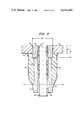
- FIG. 2 is a vertical section through a movable plate having an integral nose or collector nozzle
- FIG. 3 is a vertical section through a second movable plate having an integral nozzle for mating with an elongated pouring tube.
- the upper diameter ⁇ 1 is larger than the lower diameter ⁇ 2, the cone angle being at least 5°.
- the diameter ⁇ 1 has been chosen so that the distance d between the upper edge of the opening 2 and the internal edge of the ring-shaped recess 5 is at least three millimeters.
- the ring insert 3 of a suitable refractory material has the same depth as the plate thickness in the zone of the opening 2, and has a bore defining a flow orifice equal to the diameter of the opening originally in the plate.
- the ring insert has the same taper as that of the opening bored in the plate 1.
- the opening and insert are so dimensioned that between the inner face of the opening 2 and the outer face of the ring insert 3 there is a gap of oone millimeter for cement 4 to fasten the insert in position.
- the opening 8 in the movable plate 7 and in the upper part of the nose, which is shown in FIG. 2, is bored out to the diameter ⁇ 3 for a distance h1 from the sliding surface of the plate 7 while the remaining lower part of the nose is bored out to the diameter ⁇ 4 which is smaller than ⁇ 3.
- Distance h1 is greater than the plate thickness.
- the ring insert 9 which is to be accommodated in the larger opening portion contained in the plate and the upper part of the nose, has an outside diameter two millimeters smaller than ⁇ 3.
- the resulting gap is filled with cement 10.
- the inside diameter of the ring insert 9 has the same dimension as the opening originally in the plate 7.
- the sleeve 14, with which the opening 13 of the nose 12 is lined, is made of a cementitious material which contains 12% by weight of very thin needles in stainless steel.
- the cement mixture is pressed into the opening 13 after the ring insert 9 and the perforated tube 16 (only shown in FIG. 3) have been inserted.
- the thickness of the cement lining 14 is chosen to be such that the opening defined thereby for metal flow has the same diameter as the inside diameter of the ring insert 9.
- the diameter ⁇ 4 is chosen such that all the worn material is removed from the plate and the nose while leaving the wall of the nose with a thickness of 5 mm.
- FIG. 3 there is shown a movable plate 7 whose nose originally had a refractory material extension 19 which occupied the entire surface beneath the line A--A.
- the ring isert 9 of the height h1, which is larger than the thickness h2 of the plate 7, is placed into the opening having the diameter ⁇ 3 of the plate and into the upper part of the nose.
- a metal sleeve extension 17 is secured to the lower part of the sleeve 15' by a weld 18.
- the sleeve extension has the same shape as the original refractory material extension.
- the entire space between the perforated tube 16 and the opening of the nose as well as between the tube 16 and the sleeve extension 17 can be filled with the already-mentioned cement mixture.
Landscapes
- Engineering & Computer Science (AREA)
- Manufacturing & Machinery (AREA)
- Mechanical Engineering (AREA)
- Casting Support Devices, Ladles, And Melt Control Thereby (AREA)
- Furnace Housings, Linings, Walls, And Ceilings (AREA)
- Sliding Valves (AREA)
Applications Claiming Priority (2)
| Application Number | Priority Date | Filing Date | Title |
|---|---|---|---|
| IT23358/80A IT1131943B (it) | 1980-07-10 | 1980-07-10 | Procedimento per rigenerare o modificare piastre refrattarie dei cassetti di colata delle siviere |
| IT23358A/80 | 1981-08-07 |
Publications (1)
| Publication Number | Publication Date |
|---|---|
| US4434540A true US4434540A (en) | 1984-03-06 |
Family
ID=11206375
Family Applications (1)
| Application Number | Title | Priority Date | Filing Date |
|---|---|---|---|
| US06/308,733 Expired - Fee Related US4434540A (en) | 1980-07-10 | 1981-10-05 | Process for repairing or modifying refractory plates of ladle casting cassettes |
Country Status (10)
| Country | Link |
|---|---|
| US (1) | US4434540A (show.php) |
| AT (1) | AT389258B (show.php) |
| DD (1) | DD202342A5 (show.php) |
| DE (1) | DE3124359C2 (show.php) |
| FR (1) | FR2486429A1 (show.php) |
| GB (2) | GB2081431B (show.php) |
| HU (1) | HU181364B (show.php) |
| IT (1) | IT1131943B (show.php) |
| SE (1) | SE8104007L (show.php) |
| YU (1) | YU44324B (show.php) |
Cited By (4)
| Publication number | Priority date | Publication date | Assignee | Title |
|---|---|---|---|---|
| US4597514A (en) * | 1982-04-01 | 1986-07-01 | Uss Engineers And Consultants, Inc. | Sliding gate valves and components thereof |
| US4801055A (en) * | 1983-12-16 | 1989-01-31 | Didier-Werke Ag | Method of repairing or renewing a worn refractory plate of a sliding closure unit |
| US5190611A (en) * | 1991-02-13 | 1993-03-02 | The Boeing Company | Bearing load restoration method for composite structures |
| US5979719A (en) * | 1998-04-17 | 1999-11-09 | Vesuvius Crucible Company | Soft-bore monoblock pouring tube |
Families Citing this family (15)
| Publication number | Priority date | Publication date | Assignee | Title |
|---|---|---|---|---|
| ATE23022T1 (de) * | 1981-11-25 | 1986-11-15 | Stein Refractories | Feuerfestbestandteile. |
| IT1142623B (it) * | 1981-12-22 | 1986-10-08 | Flocon Italiana | Procedimento per rigenerare una piastra mobile di un cassetto di colata di una siviera |
| DE3243305C1 (de) | 1982-11-23 | 1989-02-23 | Egon 5650 Solingen Evertz | Verfahren zur Instandsetzung von Schieberplatten |
| DE3307193C2 (de) * | 1983-03-01 | 1986-04-17 | VGT AG, 3432 Großalmerode | Feuerfeste Schieberplatte |
| CH659872A5 (de) * | 1983-09-02 | 1987-02-27 | Stopinc Ag | Verschlussplatte fuer einen schiebeverschluss. |
| US4541553A (en) * | 1983-09-20 | 1985-09-17 | Servsteel, Inc. | Interlocking collector nozzle assembly for pouring molten metal |
| DE3527756A1 (de) * | 1985-08-02 | 1987-03-26 | Didier Werke Ag | Verfahren zum erneuern von in schieberverschluessen verwendeten feuerfesten platten |
| DE3434857C1 (de) * | 1984-09-22 | 1992-06-11 | Didier-Werke Ag, 6200 Wiesbaden | Schieberverschluss fuer den Ausguss metallurgischer Gefaesse |
| DE3517652C1 (de) * | 1985-05-15 | 1986-09-18 | Brohltal-Deumag AG, 5401 Urmitz | Reparaturset für Schieberplatten |
| FR2594728A1 (fr) * | 1986-02-25 | 1987-08-28 | Couvreur Christian | Insert destine a etre implante dans les plaques de distributeurs de coulee continue et dispositif d'usinage d'alesage tronconique desdites plaques |
| JPS645659A (en) * | 1987-06-29 | 1989-01-10 | Toshiba Ceramics Co | Method for repairing plate brick for flow rate control device |
| DE4042203C2 (de) * | 1990-12-29 | 2003-03-20 | Egon Evertz | Schieberplatte für Schieberverschlüsse von metallurgischen Gefäßen |
| DE19605240C1 (de) * | 1996-02-13 | 1997-05-07 | Zimmermann & Jansen Gmbh | Schieberplatte zum Öffnen und Schließen des Auslaufkanals eines Gießgefäßes für metallische Schmelzen, sowie Verfahren zur Reparatur einer derartigen Schieberplatte |
| DE19801921C1 (de) * | 1998-01-20 | 1999-06-24 | Didier Werke Ag | Verschlußeinheit für Schieberverschlüsse |
| DE102021004626A1 (de) | 2021-09-14 | 2023-03-16 | PiRé Feuerfeste Produkte GmbH & Co. KG | Verfahren zur Reparatur eines Schieberverschlusses |
Citations (6)
| Publication number | Priority date | Publication date | Assignee | Title |
|---|---|---|---|---|
| FR2064123A7 (en) | 1969-10-03 | 1971-07-16 | Didier Werke Ag | Continuous casting tundish |
| US3604598A (en) | 1969-07-09 | 1971-09-14 | United States Steel Corp | Outlet passage construction for teeming vessels |
| US3727805A (en) | 1972-01-24 | 1973-04-17 | Steel Corp | Mechanism for supporting a submerged pouring tube on a bottom-pour vessel and method of replacing tubes |
| DE2616685A1 (de) | 1975-05-30 | 1976-12-09 | Funabashi Steel Works Ltd | Verfahren und vorrichtung zum kontinuierlichen giessen von metall |
| FR2250594B1 (show.php) | 1973-11-12 | 1979-07-06 | Sumitomo Metal Ind | |
| US4270595A (en) | 1978-09-08 | 1981-06-02 | Georgetown Steel Corporation | Shroud with replaceable extension |
Family Cites Families (11)
| Publication number | Priority date | Publication date | Assignee | Title |
|---|---|---|---|---|
| US3628706A (en) * | 1968-10-15 | 1971-12-21 | Southwire Co | Long life spout |
| DE2165537A1 (de) * | 1971-12-30 | 1973-07-19 | Maximilianshuette Eisenwerk | Verfahren zur erhoehung der haltbarkeit und der wirtschaftlichkeit von ausgussoeffnungen an gefaessen zur aufnahme von fluessigem metall |
| GB1490981A (en) * | 1974-01-15 | 1977-11-09 | Flogates Ltd | Pouring of molten metals |
| AT342223B (de) * | 1975-07-16 | 1978-03-28 | Oesterr Amerikan Magnesit | Schieberverschluss aus feuerfestem, basischem material |
| CH595914A5 (en) * | 1975-11-17 | 1978-02-28 | Fischer Ag Georg | Mould contg. a casting pipe |
| GB1589659A (en) * | 1977-05-13 | 1981-05-20 | Vysoka Skola Chem Tech | Refractory plates |
| BE861127A (fr) * | 1977-11-23 | 1978-03-16 | Centre Rech Metallurgique | Perfectionnement apporte aux busettes de coulee continue des metaux |
| US4210617A (en) * | 1978-08-03 | 1980-07-01 | Kaiser Aluminum & Chemical Corporation | Method of casting an integral slide gate and nozzle |
| SE441421B (sv) * | 1978-09-25 | 1985-10-07 | Uss Eng & Consult | Anordning for reglering av metallflodet fran tapphalet i en gjutskenk |
| GB2060842A (en) * | 1979-08-01 | 1981-05-07 | Fichera E | Methods of repairing refractories for sliding valves and means for performing it |
| GB2065278B (en) * | 1979-12-14 | 1983-10-12 | Flogates Ltd | Composite moulded refractory articles amd their manufacture |
-
1980
- 1980-07-10 IT IT23358/80A patent/IT1131943B/it active
-
1981
- 1981-06-20 DE DE3124359A patent/DE3124359C2/de not_active Expired
- 1981-06-26 SE SE8104007A patent/SE8104007L/ not_active Application Discontinuation
- 1981-07-02 AT AT0295381A patent/AT389258B/de not_active IP Right Cessation
- 1981-07-03 YU YU1649/81A patent/YU44324B/xx unknown
- 1981-07-08 FR FR8113441A patent/FR2486429A1/fr active Granted
- 1981-07-09 HU HU812003A patent/HU181364B/hu not_active IP Right Cessation
- 1981-07-10 GB GB8121272A patent/GB2081431B/en not_active Expired
- 1981-07-10 DD DD81231674A patent/DD202342A5/de not_active IP Right Cessation
- 1981-10-05 US US06/308,733 patent/US4434540A/en not_active Expired - Fee Related
-
1983
- 1983-12-05 GB GB08332371A patent/GB2131524B/en not_active Expired
Patent Citations (6)
| Publication number | Priority date | Publication date | Assignee | Title |
|---|---|---|---|---|
| US3604598A (en) | 1969-07-09 | 1971-09-14 | United States Steel Corp | Outlet passage construction for teeming vessels |
| FR2064123A7 (en) | 1969-10-03 | 1971-07-16 | Didier Werke Ag | Continuous casting tundish |
| US3727805A (en) | 1972-01-24 | 1973-04-17 | Steel Corp | Mechanism for supporting a submerged pouring tube on a bottom-pour vessel and method of replacing tubes |
| FR2250594B1 (show.php) | 1973-11-12 | 1979-07-06 | Sumitomo Metal Ind | |
| DE2616685A1 (de) | 1975-05-30 | 1976-12-09 | Funabashi Steel Works Ltd | Verfahren und vorrichtung zum kontinuierlichen giessen von metall |
| US4270595A (en) | 1978-09-08 | 1981-06-02 | Georgetown Steel Corporation | Shroud with replaceable extension |
Cited By (4)
| Publication number | Priority date | Publication date | Assignee | Title |
|---|---|---|---|---|
| US4597514A (en) * | 1982-04-01 | 1986-07-01 | Uss Engineers And Consultants, Inc. | Sliding gate valves and components thereof |
| US4801055A (en) * | 1983-12-16 | 1989-01-31 | Didier-Werke Ag | Method of repairing or renewing a worn refractory plate of a sliding closure unit |
| US5190611A (en) * | 1991-02-13 | 1993-03-02 | The Boeing Company | Bearing load restoration method for composite structures |
| US5979719A (en) * | 1998-04-17 | 1999-11-09 | Vesuvius Crucible Company | Soft-bore monoblock pouring tube |
Also Published As
| Publication number | Publication date |
|---|---|
| DE3124359C2 (de) | 1985-03-14 |
| GB2131524A (en) | 1984-06-20 |
| IT1131943B (it) | 1986-06-25 |
| DE3124359A1 (de) | 1982-08-26 |
| GB2081431A (en) | 1982-02-17 |
| IT8023358A0 (it) | 1980-07-10 |
| HU181364B (en) | 1983-07-28 |
| FR2486429B1 (show.php) | 1984-03-16 |
| YU44324B (en) | 1990-06-30 |
| FR2486429A1 (fr) | 1982-01-15 |
| DD202342A5 (de) | 1983-09-07 |
| YU164981A (en) | 1984-10-31 |
| AT389258B (de) | 1989-11-10 |
| ATA295381A (de) | 1989-04-15 |
| GB2131524B (en) | 1984-12-12 |
| SE8104007L (sv) | 1982-01-11 |
| GB8332371D0 (en) | 1984-01-11 |
| GB2081431B (en) | 1984-07-11 |
Similar Documents
| Publication | Publication Date | Title |
|---|---|---|
| US4434540A (en) | Process for repairing or modifying refractory plates of ladle casting cassettes | |
| US3801083A (en) | Wear-resistant spouts for metallurgical vessels | |
| US3970283A (en) | Pouring of molten metals | |
| US4421257A (en) | Metal pouring nozzle with gas inlet | |
| US4708327A (en) | Discharge nozzle assembly and methods of formation and operation thereof | |
| US4091971A (en) | Molten metal nozzle having capillary gas feed | |
| US4836508A (en) | Ladle shroud with co-pressed gas permeable ring | |
| US5866022A (en) | Refractory pour tube with cast plate | |
| CA2329280C (en) | Stopper for continuous casting | |
| CA1174463A (en) | Renovation or adaptation of refractory valve plates for molten metal pouring | |
| CA2064392A1 (en) | Gas permeable well nozzle | |
| US3735906A (en) | Replaceable molten metal nozzle structure | |
| EP0282247A1 (en) | Refractory assemblies | |
| US5919392A (en) | Pouring tube structure and assembly | |
| NZ231955A (en) | Metallurgical vessel gas injection with purging plug raised above bottom lining | |
| US4570908A (en) | Furnace valve | |
| US3396877A (en) | Composite nozzle pocket block | |
| JPH11510098A (ja) | 連続鋳造機へのガスの侵入制限装置 | |
| ZA200609392B (en) | Slide plate | |
| US5112029A (en) | Quick fluid injection assembly replacement in metallurgical reacters | |
| AU695890B2 (en) | Immersed metallurgical pouring nozzles | |
| RU2187410C2 (ru) | Фланец для центробежной наплавки деталей | |
| JPH0379406B2 (show.php) | ||
| JP3558318B2 (ja) | リング状ガス吹込ノズル耐火物及びそれを用いたスライディングノズルプレート | |
| JPH0741404B2 (ja) | 取鍋の耐火性ライニングの製造法 |
Legal Events
| Date | Code | Title | Description |
|---|---|---|---|
| AS | Assignment |
Owner name: USS ENGINEERS AND CONSULTANTS, INC., 600 GRANT STR Free format text: ASSIGNMENT OF ASSIGNORS INTEREST.;ASSIGNOR:FLOCON ITALIANA S.R.1.;REEL/FRAME:004191/0449 Effective date: 19811005 Owner name: FLOCON ITALIANA S.R.L., GALLERIA S. BABILA, 4/A, M Free format text: ASSIGNMENT OF ASSIGNORS INTEREST.;ASSIGNOR:CAPPELLI, ROMANO;REEL/FRAME:004191/0444 Effective date: 19811005 |
|
| MAFP | Maintenance fee payment |
Free format text: PAYMENT OF MAINTENANCE FEE, 4TH YEAR, PL 96-517 (ORIGINAL EVENT CODE: M170); ENTITY STATUS OF PATENT OWNER: LARGE ENTITY Year of fee payment: 4 |
|
| AS | Assignment |
Owner name: USX CORPORATION, A CORP. OF DE, STATELESS Free format text: MERGER;ASSIGNOR:UNITED STATES STEEL CORPORATION (MERGED INTO);REEL/FRAME:005060/0960 Effective date: 19880112 |
|
| FEPP | Fee payment procedure |
Free format text: MAINTENANCE FEE REMINDER MAILED (ORIGINAL EVENT CODE: REM.); ENTITY STATUS OF PATENT OWNER: LARGE ENTITY |
|
| FEPP | Fee payment procedure |
Free format text: SURCHARGE FOR LATE PAYMENT, PL 96-517 (ORIGINAL EVENT CODE: M176); ENTITY STATUS OF PATENT OWNER: LARGE ENTITY |
|
| MAFP | Maintenance fee payment |
Free format text: PAYMENT OF MAINTENANCE FEE, 8TH YEAR, PL 96-517 (ORIGINAL EVENT CODE: M171); ENTITY STATUS OF PATENT OWNER: LARGE ENTITY Year of fee payment: 8 |
|
| FEPP | Fee payment procedure |
Free format text: MAINTENANCE FEE REMINDER MAILED (ORIGINAL EVENT CODE: REM.); ENTITY STATUS OF PATENT OWNER: LARGE ENTITY |
|
| LAPS | Lapse for failure to pay maintenance fees | ||
| FP | Lapsed due to failure to pay maintenance fee |
Effective date: 19960306 |
|
| STCH | Information on status: patent discontinuation |
Free format text: PATENT EXPIRED DUE TO NONPAYMENT OF MAINTENANCE FEES UNDER 37 CFR 1.362 |