US4380877A - Fluid circulation apparatus using fluid flow deflection grating - Google Patents
Fluid circulation apparatus using fluid flow deflection grating Download PDFInfo
- Publication number
- US4380877A US4380877A US06/286,397 US28639781A US4380877A US 4380877 A US4380877 A US 4380877A US 28639781 A US28639781 A US 28639781A US 4380877 A US4380877 A US 4380877A
- Authority
- US
- United States
- Prior art keywords
- grating
- fluid
- flow
- plane
- perforations
- Prior art date
- Legal status (The legal status is an assumption and is not a legal conclusion. Google has not performed a legal analysis and makes no representation as to the accuracy of the status listed.)
- Expired - Fee Related
Links
Images

Classifications
-
- F26B21/20—
-
- F—MECHANICAL ENGINEERING; LIGHTING; HEATING; WEAPONS; BLASTING
- F15—FLUID-PRESSURE ACTUATORS; HYDRAULICS OR PNEUMATICS IN GENERAL
- F15D—FLUID DYNAMICS, i.e. METHODS OR MEANS FOR INFLUENCING THE FLOW OF GASES OR LIQUIDS
- F15D1/00—Influencing flow of fluids
- F15D1/001—Flow of fluid from conduits such as pipes, sleeves, tubes, with equal distribution of fluid flow over the evacuation surface
-
- F26B21/50—
Definitions
- the present invention relates to a deflection grating and to circulation apparatus using the grating. It is particularly applicable to circulation chambers used to put a gas into contact with a solid as in a dryer or a furnace, or to put a gas into contact with a liquid or with a solid in suspension in the apparatus, as in a cleaning, absorption or cooling tower.
- Fluid circulation chambers generally include an inlet fluid distributor grating and an outlet fluid collector grating.
- the inlet grating is intended to deflect the flow and to decelerate the fluid, while the outlet grating is intended to deflect the flow and to accelerate the fluid, the idea being to obtain uniform fluid velocity between the gratings.
- the inlet and/or outlet gratings are constituted by thin, plane, perforated metal sheets which are generally associated with inlet and outlet passages of constant height. Since the thinly-edged perforations through these grids have no effect on the tangential components of the inlet air velocity, large oblique velocity components remain inside the chamber in spite of the spreading out effect of the inlet grating. These high velocity components, combined with the effect of the walls of the chamber, leave the air un-evenly spread out inside the chamber.
- a system for correcting inlet flow may be improved by creating a flow deflecting effect using a thick perforated sheet, such that the ratio of the sheet thickness to the diameter of the perforations is high, and in any case greater than five. Any fluid entering such perforations obliquely tends to stick to the walls thereof and thus leaves flowing along a direction substantially perpendicular to the plane of the sheet.
- This arrangement suffers from the drawback of either requiring sheets that are thick, heavy and expensive, or else requiring medium thickness sheets that are perforated by very small holes which tend to become clogged with any solid particles that may be in suspension in drying air, for example.
- honey-comb panel of sufficient thickness to deflect the flow appreciably.
- a honey-comb has the disadvantage of head loss that is low, and highly variable depending on the angle of incidence of the fluid on its inlet side.
- Honey-combs are thus primarily used in situations where the fluid to be deflected is is itself applied to the panel at a speed and along a direction that are both uniform and regular. This can require the addition of a perforated sheet to provide improved spreading out of the fluid at the cost of extra average head loss.
- An additional drawback is that glued honey-combs are useable only at fairly low temperatures.
- a large suction pressure difference must be created along the outlet passage to enable the air to leave it rapidly in a direction which is generally perpendicular to the plane of the outlet sheet. This pressure difference further upsets the uniformity of flow through the chamber.
- One way of combatting the effects of the suction pressure difference required along the outlet passage is to use an outlet grating that causes a head loss which is large in comparison with the suction pressure difference. This leads to the use of sheets with excessive head losses giving mediocre results even when used in conjunction with divergent passages.
- Preferred embodiments of the invention provide gratings which ensure adequate uniformity in the flow of fluid downstream from an inlet grating and/or upstream from an outlet grating. This is done simply and without excessive head loss.
- the present invention provides afluid flow deflection grating for receiving an incident flow of fluid arriving along an incident direction and for forming an exit flow of fluid leaving along an exit direction that is at least 45° different from the incident direction and with fluid flow that is substantially uniform over its entire cross section at a distance from the grating, wherein said grating is generally in the shape of a panel constituted by at least one thin corrugated and perforated sheet, each corrugation being in the form of at least two substantially plane strips extending lengthwise in a direction perpendicular to both the incident and the exit directions, and at least some of the perforations in said sheet being through those of said strips whose plane is substantially perpendicular to the exit direction.
- the grating is disposed as a panel extending perpendicularly to the exit direction and each corrugation of the sheet preferably comprises, from the exit side to the inlet side:
- a bottom strip that is substantially plane and parallel to the average plane of the panel, the width of said bottom strip being not more than 1.5 times the projection of the corrugation pitch on a plane perpendicular to the incident direction, said bottom strip being perforated by main perforations;
- the height of the corrugations is preferably from 1.5 to 5 times the width of the bottom strip.
- the grating is disposed as a panel extending perpendicularly to the incident direction and each corrugation of the sheet preferably comprises:
- the perforation through the perforated strip extending substantially over its entire width such that fluid leaves through said perforations in oblique jets that do not stick to the panel, said jets diffusing to reconstitute a downstream flow that is uniform and steeply inclined to the plane of the panel.
- the invention also provides fluid circulation apparatus for causing an object to interact with a uniform flow of fluid through a chamber, wherein the apparatus includes an inlet grating as defined above, and means for holding said object downstream from the inlet grating at a distance that is at least ten times the pitch of the corrugations of the inlet grating.
- FIG. 1 is a diagrammatic transverse section through a prior art dryer.
- FIG. 2 is a diagrammatic transverse section through a dryer incorporating gratings embodying the invention.
- FIG. 3 is a diagrammatic perspective view of a part of the inlet grating shown in FIG. 1.
- FIG. 4 is a diagrammatic perspective view of a second dryer incorporating gratings embodying the invention.
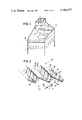
- FIG. 5 is a diagrammatic perspective view of a part of a dryer outlet grating embodying the invention.
- Drying and in particular drying a multitude of objects that must not be allowed to touch one another until dry, often leads to the use of large drying chambers in which the objects being dried do not offer much resistance to the flow of hot drying gas.
- the drying fluid must be at uniform temperature and humidity, and it must be made to flow at uniform speed past the objects being dried wherever they are located in the chamber. Further, the fluid must circulate fast enough to ensure high dryer throughput and thereby reduce the overheads, per item dried, of capital expenditure and of heat losses through the dryer walls.
- the drying fluid is generally recycled over the product being dried, which requires suitable re-heating and drying, e.g. by bleeding off a fraction of hot wet air and replacing it with fresh dry air.
- the space available for housing the fluid recycling equipment is generally so small that the fluid is made to flow through it at a much higher speed than it flows through the drying chamber. There is thus a need both to admit air at high speed into the chamber under adequate control, and to remove it therefrom. Both of these functions are performed by using deflection gratings in accordance with the invention.
- a prior art drying chamber 1 contains sheets or "curtains" of pasta 18 suspended from horizontal canes 2.
- the canes and their loads of pasta move horizontally through the dryer in a direction perpendicular to the plane of the figure.
- a curtain of pasta is shown.
- the chamber is enclosed by a thermally insulating wall 6, inside which the air is recycled by a fan 3 and passed through a battery of heater elements 4 located in a side passage 5.
- Hot air then passes into an upper inlet passage 7 whence it passes through a plane inlet grating 11 above the curtain of pasta.
- the air speed in the upper passage 7 may be more than three to five times the average desired air speed over the pasta to be dried.
- FIG. 1 To simplify FIG. 1, the apparatus required for bleeding off hot wet air and for introducing fresh dry air has not been shown. In practice such apparatus is controlled to ensure a desired average humidity of the drying air.
- FIG. 2 is a similar diagram to FIG. 1, and shows a dryer incorporating the invention to obtain a well-distributed flow of drying air over pasta.
- Air coming from the side passage 5 flows into the upper passage 7 after deflection in conventional manner through a deflection grating 9.
- the upper passage 7 converges by virtue of the top wall 10 of the dryer being disposed on a slope.
- the cross section of the upper passage 7 thus gets smaller linearly which, as is well known, is the theoretical requirement for ensuring compatibility between uniform removal of air through the inlet deflection grating, and uniform air speed and air pressure inside the passage 7.
- the outlet grating 12 deflects and accelerates the air and sends it obliquely into the lower passage 8 which diverges by virtue of the bottom wall 13 of the dryer being on a slope.
- the cross section of the lower passage 8 gets larger linearly in a manner suitable for ensuring uniform flow through the outlet grating 12.
- the air speed and pressure can thus be made uniform inside the inlet passage 7, inside the drying chamber 1 around the pasta, and inside the outlet passage 8, provided that the inlet grating 11 deflects the oblique flow along the inlet passage 7 into a vertical flow past the pasta, and provided the outlet grating 12 deflects the vertical flow past the pasta into a suitably oblique flow to match the slope of the bottom wall 13.
- FIG. 3 A detail of part of the inlet deflection grating 11 is shown in FIG. 3. It is made by stamping a thin panel to obtain corrugations defining conventionally, peaks and valleys, said corrugations having rounded tops 15 on the side of the inlet passage 7. The corrugations are parallel and they are spaced at a pitch 14. The rounded tops 15 run into flanks 16 on their upstream sides relative to the flow in the passage 7 and 16' on their downstream sides. The direction of flow is shown by an arrow 25. The flanks are straight and inclined to the normal to the plane of the panel. They form troughs 19 which converge slightly towards their bottoms 23 forming said valleys in which there are perforations 20 with connecting tongues 21 in between.
- the bottoms of the troughs may be substantially flat, or they may be rounded.
- the width 17 at the bottom of a trough 19 is not more than 1.5 times the projection of the corrugation pitch 14 on a plane perpendicular to the generally oblique direction 25 of the incident air flow. Under normal conditions, this results in the approach speed of the air that is deflected to the bottom of the troughs being at least equal to 0.6 times the speed of the incident flow.
- the perforations should not occupy more than 85% of the bottoms of the troughs in order to ensure that the remaining tongues 21 are wide enough to provide adequate mechanical strength for the panel.
- the perforations may occupy as little as 50% of the available area in order to improve the distributing effect of the grating, but this will be at the expense of increased head loss.
- the height 26 of a trough should be between 1.5 and 5 times the width 17 of the bottom of a trough.
- the flanks 16 and 16' should not be inclined at more than 20° from the normal to the plane of the panel.
- the fluid leaves the perforations 20 in the form of high-speed jets, which diffuse to form a flow of uniform speed at a distance downstream from the grating that is about ten times the corrugation pitch 14.
- a deflection grating of given shape adapted to a particular angle of incidence retains its properties of deflection and distribution over a wide range of angles of incidence ranging from normal to the grating to some maximally oblique angle.
- the flow comes unstuck at the rounded edges 15' of the corrugation tops 15 and then strikes and bounces off the downstream flanks 16 of the troughs 19. This can even lead to the jets coming out of the perforations 20 flowing in substantially the opposite direction to the incident flow 25.
- auxiliary perforations 24 may be provided in the upstream flanks 16 of the troughs just below the tops 15. Fluid sucked in through the auxiliary perforations 24 prevents the flow from coming unstuck over a further range of increasingly oblique angles of incidence.
- the fluid sucked in through the auxiliary perforations 24 helps fill out the flow in between the jets through the main perforations 20, and thus improves the uniformity of the flow downstream from the panel.
- the area of the auxiliary perforations as a whole should not exceed that of the main perforations.
- a deflection grating as shown in FIG. 3 has important aerodynamic features as well as important technical and economic features.
- the grating adjusts to a wide range of angles of incidence. This is due in particular to the rounded shape of the tops 15 and to the converging shape of the troughs 19 in between the rounded flanks 16 and 16'.
- This combination of features of shape causes the flow through the throughs to be substantially without loss of speed or head.
- the head loss due to the grating is only slightly dependant on the angle of incidence, with nearly all the loss being due to the flow through the main perforations 20 opening suddenly into a larger space.
- the grating thus has nearly the minimum possible loss compatible with its functions of diverting and spreading out a flow of fluid that arrives obliquely at the grating.
- the grating is manufactured by stamping, which gives a highly regular, rigid and light grating without any welding, soldering or glueing. This means that if the grating is made of metal there is no difficulty in working at high temperatures. Further, due to its rounded shape facing the fluid flow and to its lack of re-entrant corners, there is little tendency for it to becomes clogged with particles of dirt.
- the pitch of the corrugations is chosen to be less than one tenth of the distance between the grating and the pasta 18 to ensure uniform flow over the curtains of pasta.
- a grating in accordance with the invention is not limited to a case where the incident air arrives at an oblique angle.
- a tower shaped drying chamber as shown in FIG. 4 may use two gratings 11 and 11'. Hot air enters flowing downwards in a funnel shaped portion above a generally cubic drying chamber and passes through both gratings which are disposed horizontally one above the other before entering the drying chamber proper. The two gratings are crossed such that their corrugations are at right angles to each other, thereby ensuring a very even distribution of air downstream from the lower grating.
- FIG. 5 shows an embodiment of the outlet grating 12 from the chamber 1 for directing air into the outlet passage 8.
- the outlet grating 12 serves to accelerate the air and to deflect it from the direction of flow indicated by the arrow 25' to the direction indicated by the arrow 42'.
- the grating 12 is constituted by a thin sheet in which perforations 33 are initially formed. Then the sheet is folded or corrugated thus defining conventionally peaks and valleys in a stamping operation to form parallel ridges 30 spaced apart at a pitch 29.
- the non-perforated portions of the ridges 30 constitute guide portions or guide stripes that are inclined at an angle 31 to the general plane of the grating, and the steeper the angle of deflection, the smaller the angle 31.
- the perforated portions of the ridges 30 comprise tongues 32 and perforations 33 in between the tongues.
- the perforations 33 are square, but they could equally well be rectangular, oblong or circular.
- the fluid flow arriving downwardly on the grating 12 is separated into flows proper to each ridge by the leading edges 34 of the ridges 30, and each flow is then deflected by the adjacent guide portion to flow out through the perforations 33.
- the ridges are asymmetrical, with the projection 37 of the perforated portion on a horizontal plane being smaller than the projection 38 of the guide portion.
- the sum of the projections 37 and 38 is the pitch 29.
- the limiting factor in reducing the smaller projection 37 is the extent to which the tongues 32 can be bent without excessively weakening the grating.
- the projection 37 will be about twice the minimum internal bending radius of the sheet from which the grating is made. It is thus typically five times the thickness of the sheet.
- the outlet angle and speed vary as a function of the angle of approach compared to the normal to the plane of the grating.
- the outlet angle varies little for angles of arrival within 20° of the normal, so the grating can then be used anywhere in this range, so it might be placed at an angle to the outlet from the drying chamber.
- Outlet gratings in accordance with the invention have deflection and distribution capacities, particularly when used in conjunction with a divergent outlet passage 8, that are close to the maximum capacities that could theoretically be obtained with a grating using turbine type blades, but they have the advantages of simplicity and cheapness in manufacture, and being strong enough to be used in large formats.
Landscapes
- Engineering & Computer Science (AREA)
- Physics & Mathematics (AREA)
- Fluid Mechanics (AREA)
- Mechanical Engineering (AREA)
- General Engineering & Computer Science (AREA)
- Drying Of Solid Materials (AREA)
- Physical Or Chemical Processes And Apparatus (AREA)
Applications Claiming Priority (2)
| Application Number | Priority Date | Filing Date | Title |
|---|---|---|---|
| FR8016221A FR2487450A1 (fr) | 1980-07-23 | 1980-07-23 | Chambre de circulation d'un courant de fluide |
| FR8016221 | 1980-07-23 |
Publications (1)
| Publication Number | Publication Date |
|---|---|
| US4380877A true US4380877A (en) | 1983-04-26 |
Family
ID=9244441
Family Applications (1)
| Application Number | Title | Priority Date | Filing Date |
|---|---|---|---|
| US06/286,397 Expired - Fee Related US4380877A (en) | 1980-07-23 | 1981-07-23 | Fluid circulation apparatus using fluid flow deflection grating |
Country Status (6)
| Country | Link |
|---|---|
| US (1) | US4380877A (enExample) |
| EP (1) | EP0044529B1 (enExample) |
| JP (1) | JPS5765315A (enExample) |
| CA (1) | CA1163798A (enExample) |
| DE (1) | DE3161892D1 (enExample) |
| FR (1) | FR2487450A1 (enExample) |
Cited By (11)
| Publication number | Priority date | Publication date | Assignee | Title |
|---|---|---|---|---|
| US4757800A (en) * | 1987-01-14 | 1988-07-19 | Lincoln Foodservice Products, Inc. | Air flow system for a low profile impingement oven |
| US5414944A (en) * | 1993-11-03 | 1995-05-16 | Culp; George | Method and apparatus for decreasing separation about a splitter plate in a kiln system |
| US5488785A (en) * | 1993-09-23 | 1996-02-06 | Culp; George | Controlled upper row airflow method and apparatus |
| US6219937B1 (en) | 2000-03-30 | 2001-04-24 | George R. Culp | Reheaters for kilns, reheater-like structures, and associated methods |
| US6370792B1 (en) | 2000-09-01 | 2002-04-16 | George R. Culp | Structure and methods for introducing heated ari into a kiln chamber |
| US6467190B2 (en) | 2000-03-22 | 2002-10-22 | George R. Gulp | Drying kiln |
| US20110125332A1 (en) * | 2009-11-20 | 2011-05-26 | Halliburton Energy Services, Inc. | Systems and Methods for Specifying an Operational Parameter for a Pumping System |
| US20110308435A1 (en) * | 2010-06-16 | 2011-12-22 | Clyde Bergemann Drycon Gmbh | Conveying means and method for conveying hot material |
| ITVI20110209A1 (it) * | 2011-07-29 | 2013-01-30 | Feltre Srl | Impianto di essiccazione per pelli con circolazione d'aria perfezionata |
| US11060769B2 (en) * | 2017-11-29 | 2021-07-13 | Lg Electronics Inc. | Refrigerator |
| IT202000004933A1 (it) * | 2020-03-09 | 2021-09-09 | Storci S P A | Apparato per l’essiccazione di un prodotto |
Families Citing this family (3)
| Publication number | Priority date | Publication date | Assignee | Title |
|---|---|---|---|---|
| DE19720065C1 (de) * | 1997-05-14 | 1998-12-17 | Helmut Fresenberger | Ofen zum Trocknen von lackierten Proben |
| FR2911393B1 (fr) * | 2007-01-16 | 2009-04-03 | 3A Soc Responsabilite Limitee | Unite mobile de sechage des produits de finition |
| CN111076498B (zh) * | 2019-12-25 | 2021-06-11 | 广东利元亨智能装备股份有限公司 | 电芯的干燥方法 |
Citations (3)
| Publication number | Priority date | Publication date | Assignee | Title |
|---|---|---|---|---|
| US1293799A (en) * | 1916-06-30 | 1919-02-11 | Pacific Evaporator Company | Drier. |
| SE107009C1 (enExample) | 1938-03-04 | 1943-03-30 | ||
| US4304053A (en) * | 1979-06-05 | 1981-12-08 | Vereinigte Fubereien und Appretur AG | Steam and hot air operated drying device and method for textile articles of clothing |
Family Cites Families (7)
| Publication number | Priority date | Publication date | Assignee | Title |
|---|---|---|---|---|
| FR975566A (fr) * | 1942-02-21 | 1951-03-07 | Anciens Ets Brissonneau & Lotz | Perfectionnements aux appareils de chauffage ou de refroidissement des produits alimentaires |
| GB718418A (en) * | 1950-01-21 | 1954-11-17 | Julien Dungler | Improvement in method and apparatus for treating fibrous sheet material by superheated steam or vapours |
| FR1088468A (fr) * | 1952-11-28 | 1955-03-08 | Courtaulds Ltd | Perfectionnements aux séchoirs-tunnels |
| FR1497984A (fr) * | 1966-10-28 | 1967-10-13 | Windmoeller & Hoelscher | Dispositif pour le traitement de feuilles continues de matériau en mouvement, de préférence de feuilles continues de papier ou de matière plastique, à l'aide d'un fluide gazeux |
| US3765103A (en) * | 1971-12-03 | 1973-10-16 | Foamat Foods Corp | Plural gas stream dryer |
| DE2547902C3 (de) * | 1975-10-25 | 1979-09-13 | Albert-Frankenthal Ag, 6710 Frankenthal | Trockungskasten für bedruckte Bogen |
| US4173831A (en) * | 1978-04-26 | 1979-11-13 | Diamond International Corporation | Egg drying apparatus |
-
1980
- 1980-07-23 FR FR8016221A patent/FR2487450A1/fr active Granted
-
1981
- 1981-07-16 EP EP81105578A patent/EP0044529B1/fr not_active Expired
- 1981-07-16 DE DE8181105578T patent/DE3161892D1/de not_active Expired
- 1981-07-21 JP JP56114326A patent/JPS5765315A/ja active Pending
- 1981-07-22 CA CA000382298A patent/CA1163798A/fr not_active Expired
- 1981-07-23 US US06/286,397 patent/US4380877A/en not_active Expired - Fee Related
Patent Citations (3)
| Publication number | Priority date | Publication date | Assignee | Title |
|---|---|---|---|---|
| US1293799A (en) * | 1916-06-30 | 1919-02-11 | Pacific Evaporator Company | Drier. |
| SE107009C1 (enExample) | 1938-03-04 | 1943-03-30 | ||
| US4304053A (en) * | 1979-06-05 | 1981-12-08 | Vereinigte Fubereien und Appretur AG | Steam and hot air operated drying device and method for textile articles of clothing |
Cited By (14)
| Publication number | Priority date | Publication date | Assignee | Title |
|---|---|---|---|---|
| US4757800A (en) * | 1987-01-14 | 1988-07-19 | Lincoln Foodservice Products, Inc. | Air flow system for a low profile impingement oven |
| US5488785A (en) * | 1993-09-23 | 1996-02-06 | Culp; George | Controlled upper row airflow method and apparatus |
| US5414944A (en) * | 1993-11-03 | 1995-05-16 | Culp; George | Method and apparatus for decreasing separation about a splitter plate in a kiln system |
| US6467190B2 (en) | 2000-03-22 | 2002-10-22 | George R. Gulp | Drying kiln |
| US6652274B2 (en) | 2000-03-22 | 2003-11-25 | George R. Culp | Kiln and kiln-related structures, and associated methods |
| US6219937B1 (en) | 2000-03-30 | 2001-04-24 | George R. Culp | Reheaters for kilns, reheater-like structures, and associated methods |
| US6370792B1 (en) | 2000-09-01 | 2002-04-16 | George R. Culp | Structure and methods for introducing heated ari into a kiln chamber |
| US20110125332A1 (en) * | 2009-11-20 | 2011-05-26 | Halliburton Energy Services, Inc. | Systems and Methods for Specifying an Operational Parameter for a Pumping System |
| US8543245B2 (en) * | 2009-11-20 | 2013-09-24 | Halliburton Energy Services, Inc. | Systems and methods for specifying an operational parameter for a pumping system |
| US20110308435A1 (en) * | 2010-06-16 | 2011-12-22 | Clyde Bergemann Drycon Gmbh | Conveying means and method for conveying hot material |
| US8733255B2 (en) * | 2010-06-16 | 2014-05-27 | Clyde Bergemann Drycon Gmbh | Conveying means and method for conveying hot material |
| ITVI20110209A1 (it) * | 2011-07-29 | 2013-01-30 | Feltre Srl | Impianto di essiccazione per pelli con circolazione d'aria perfezionata |
| US11060769B2 (en) * | 2017-11-29 | 2021-07-13 | Lg Electronics Inc. | Refrigerator |
| IT202000004933A1 (it) * | 2020-03-09 | 2021-09-09 | Storci S P A | Apparato per l’essiccazione di un prodotto |
Also Published As
| Publication number | Publication date |
|---|---|
| EP0044529A1 (fr) | 1982-01-27 |
| CA1163798A (fr) | 1984-03-20 |
| EP0044529B1 (fr) | 1984-01-11 |
| DE3161892D1 (en) | 1984-02-16 |
| FR2487450A1 (fr) | 1982-01-29 |
| FR2487450B1 (enExample) | 1984-04-06 |
| JPS5765315A (en) | 1982-04-20 |
Similar Documents
| Publication | Publication Date | Title |
|---|---|---|
| US4380877A (en) | Fluid circulation apparatus using fluid flow deflection grating | |
| US4198215A (en) | Fin deflector for separating liquid from a liquid/vapor mixture | |
| US4769186A (en) | Gas liquid tower structure | |
| EP0725917B1 (en) | Heat exchanger with spaced evaporative wicks and method of cooling air using spaced evaporative wicks | |
| US5320651A (en) | Cross-flow film fill media with intergral drift eliminator | |
| CN111928719B (zh) | 填料模块和冷却塔 | |
| JP4087059B2 (ja) | 空気処理ユニット | |
| CA1149729A (en) | Air channeling device for mixing dry and humid air streams of a combined wet and dry atmospheric cooler | |
| US4367183A (en) | Air channeling device for mixing dry and humid air streams of a combined wet and dry atmospheric cooler | |
| GB2045913A (en) | Fluid flow arrangements | |
| EP3225816A1 (en) | Synthetic media pads for an evaporative cooler and method for evaporative cooling | |
| US5312464A (en) | Cross-flow film fill media with drift eliminator | |
| US4954148A (en) | Apparatus for treating gas | |
| WO2001051868A1 (en) | Drift eliminator | |
| US4991646A (en) | Air flow distribution baffle | |
| JPS62211258A (ja) | 気体又は液体媒体を用いてウエブ状材料を浮遊させてガイドするための装置 | |
| US4271602A (en) | Air nozzle for a jet dryer | |
| JPS6027284B2 (ja) | ヘア−ドライヤ | |
| KR20240007761A (ko) | 구조화된 패킹 및 이를 이용하는 교차 유동 접촉기 | |
| US5427718A (en) | Upper and lower crossflow film fill stack for a cooling tower | |
| US4579694A (en) | Wet deck fill | |
| US5975503A (en) | Structured packing assembly | |
| US3982914A (en) | Drift eliminators for evaporative cooling towers | |
| US5112537A (en) | Perforated arch-shaped fill bar for splash type water cooling tower | |
| JPH06222190A (ja) | 蒸気乾燥器及び気水分離システム並びに湿分分離器 |
Legal Events
| Date | Code | Title | Description |
|---|---|---|---|
| AS | Assignment |
Owner name: SOCIETE ANONYME DITE: ALSTHOM-ATLANTIQUE 38, AVENU Free format text: ASSIGNMENT OF ASSIGNORS INTEREST.;ASSIGNOR:POUX, JACQUES;REEL/FRAME:004081/0197 Effective date: 19810703 Owner name: SOCIETE ANONYME DITE: ALSTHOM-ATLANTIQUE, FRANCE Free format text: ASSIGNMENT OF ASSIGNORS INTEREST;ASSIGNOR:POUX, JACQUES;REEL/FRAME:004081/0197 Effective date: 19810703 |
|
| FEPP | Fee payment procedure |
Free format text: MAINTENANCE FEE REMINDER MAILED (ORIGINAL EVENT CODE: REM.); ENTITY STATUS OF PATENT OWNER: LARGE ENTITY |
|
| LAPS | Lapse for failure to pay maintenance fees | ||
| STCH | Information on status: patent discontinuation |
Free format text: PATENT EXPIRED DUE TO NONPAYMENT OF MAINTENANCE FEES UNDER 37 CFR 1.362 |
|
| FP | Lapsed due to failure to pay maintenance fee |
Effective date: 19870426 |