US4288203A - Multi-flow gas dynamic pressure-wave machine - Google Patents
Multi-flow gas dynamic pressure-wave machine Download PDFInfo
- Publication number
- US4288203A US4288203A US06/069,121 US6912179A US4288203A US 4288203 A US4288203 A US 4288203A US 6912179 A US6912179 A US 6912179A US 4288203 A US4288203 A US 4288203A
- Authority
- US
- United States
- Prior art keywords
- rotor
- gas
- wave machine
- pressure
- cell walls
- Prior art date
- Legal status (The legal status is an assumption and is not a legal conclusion. Google has not performed a legal analysis and makes no representation as to the accuracy of the status listed.)
- Expired - Lifetime
Links
Images


Classifications
-
- F—MECHANICAL ENGINEERING; LIGHTING; HEATING; WEAPONS; BLASTING
- F04—POSITIVE - DISPLACEMENT MACHINES FOR LIQUIDS; PUMPS FOR LIQUIDS OR ELASTIC FLUIDS
- F04F—PUMPING OF FLUID BY DIRECT CONTACT OF ANOTHER FLUID OR BY USING INERTIA OF FLUID TO BE PUMPED; SIPHONS
- F04F13/00—Pressure exchangers
Definitions
- the present invention relates to a multi-flow gas-dynamic pressure-wave machine.
- a pressure-wave machine is disclosed, for example, in U.S. Application Ser. No. 932,954 of Nicolaus Croes et al, filed Aug. 11, 1978, now Pat. No. 4,232,999 the disclosure of which is incorporated herein by reference.
- Another object of the invention is to reduce the noise level produced by pressure wave machines.
- a multi-flow gas-dynamic pressure-wave machine of the type comprising a rotor.
- the rotor includes a hub tube and a shroud located radially outwardly thereof to form a cell zone therewith for receiving a gaseous working media.
- the cell zone is subdivided into at least two concentric flow channels by means of intermediate tube means arranged between the hub tube and the shroud. Cell walls are disposed in each channel.
- a housing encloses the rotor.
- An air housing and a gas housing are provided. The latter includes ducts for the supply and removal of the gaseous working media relative to the rotor.
- the cell walls of one flow channel and the cell walls of an adjacent flow channel are circumferentially staggered with respect to one another by essentially one-half the circumferential interface between such cells.
- FIG. 1 is a longitudinal section of a dual-flow pressure-wave machine according to the invention
- FIG. 2 is a cross-sectional view of the machine taken along line II--II in FIG. 1, to show the exhaust and air ducts in a side part of the housing,
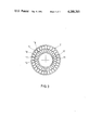
- FIG. 3 is a cross-sectional view through the rotor of the machine according to FIG. 1,
- FIG. 4 shows the design of the control edges of the air and gas housing in a preferred embodiment
- FIG. 5 shows a further preferred embodiment of the control ducts
- FIG. 6 shows a preferred embodiment of the cell walls and of the intermediate tube of the rotor
- FIG. 7 shows a further advantageous embodiment of the intermediate tube of the rotor
- FIG. 8 shows an embodiment of the rotor with unequal cell divisions
- FIG. 9 shows a triple-flow rotor.
- numeral 1 designates a housing shell surrounding a rotor 2. This rotor is rigidly joined to a shaft 3 which is supported for rotation in two bearings 4 and 5 and can be driven by a V-belt pulley 6.
- Gases coming, for example, from an internal combustion engine enter the gas housing 8 at the connecting inlet 7 where the gas flow is split into two partial flows by a partition 9.
- the rotor 2 comprises a hub tube 10, a shroud 11 and an intermediate tube 12.
- the area between the hub tube 10 and the shroud 11 constitutes a cell zone which is subdivided into separate flow channels by the intermediate tube 12.
- the hub tube 10 and intermediate tube 12 form the boundaries of an inner flow channel 13.
- the hub tube 10 and the shroud 11 form the boundaries of an outer flow channel 14. It can be seen from the side elevation of the rotor, shown in FIG. 3, that the hub tube 10 and the shroud 11 are of annular-cylindrical construction, while the intermediate tube 12 has a concertina-shaped cross-section.
- the two flow channels 13 and 14, which are concentric, are subdivided in the direction of the circumferential periphery by inner and outer radial cell walls 15 and 16, respectively, into a number of inner and outer cells 17, 18.
- the cells 17 are identical, and the cells 18 are identical.
- the inner and outer cells are circumferentially staggered by a distance amounting to essentially one-half of the circumferential interface between the inner and outer cells, i.e., by one-half of a cell width.
- the circular area occupied by all cells, including the cell walls, can be distributed to the two flow channels preferably with identical heights (i.e., radial dimension) or identical areas.
- the distribution by equal heights is more advantageous thermodynamically while a distribution by equal areas produces a greater reduction in noise. If it is more important, therefore, to reduce the noise level the distribution will be by equal areas whereby the cross-sectional area of flow channel 13 equals that of flow channel 14.
- the radially inner ends of the cell walls 16 of the outer flow channel 14 intersect the concertina-shaped intermediate tube 12 at the highest points, i.e., radially outermost points, thereof in each case.
- the cell walls extend between the hub tube 10 and the shroud 11, respectively, and the crests of the concertina-shaped intermediate tube 12 which are facing them in each case.
- FIG. 2 shows a front view of the flange side of the gas housing 8 according to the section line II--II indicated in FIG. 1.
- numeral 19 designates inlet ducts for the high-pressure exhaust gas
- numeral 20 designates gas pockets which enlarge the operating range of the pressure-wave machine in a known manner (e.g., see above-mentioned U.S. application Ser. No. 932,954)
- numeral 21 designates a low pressure outlet duct for the expended exhaust gas.
- Corresponding inlet and outlet ducts for the air sucked-in and compressed, as well as gas pockets are also provided at the flange side of the air housing 22 (see FIG. 1).
- the inlet ducts 19 for the high-pressure gas, and also the gas pockets 20, are each interrupted in the radial direction by partitions.
- partitions 9 divide the inlet duct 19 into sections 19A, 19B and partitions 35 divide the pockets 20 into sections 20A, 20B.
- FIG. 2 shows that the control edges, or boundary edges 19C, of the ducts 19 and the boundary edges 21A of the ducts 21, formerly edges 20C, of the pocket 20 (which edges 19C, 21A, 20C run transversely of the direction of the rotor periphery), are straight and extend radially.
- the cell walls 15, 16 of the rotor 2 are also constructed to be radial and straight, as is the case with the rotor construction shown in FIG. 3, the cell ducts of the inner and outer flow channels of the rotor open rather abruptly with respect to the stationary ducts in the air and gas housing.
- the free duct cross-section increases rapidly.
- the shock-like inflow of gas or air caused by this sudden increase in cross-section leads to subjectively more unpleasant noises since, due to the resulting pressure profile, component of higher frequency are created which it would be desirable to eliminate or at least reduce.
- the control edge 23 according to the embodiment of FIG. 4 of a low-pressure gas duct is a straight line which, with reference to the circle defined by the shroud 11, assumes the position of a secant which, together with the radial line 24, forms an angle 25.
- the edge 23 can also be considered to be a tangent relative to an imaginary circle 26, the center of which is defined by the axis of the rotor.
- the control edge 23 could also be inclined in the other direction with respect to the radial line 24, of course, i.e., the radially inner end of the edge 23 disposed on the opposite side of the rotor axis.
- the second, rear control edge 27 ("rear” in the sense of rotor rotation indicated by arrows) is also constructed to be inclined with respect to the radial line at the point concerned, so that the inflow of gas (or air) into the rotor cells is throttled not in a shock-like manner but, as mentioned above, gradually, which also contributes to the reduction in noise.
- FIG. 5 shows another form of the control edges, also for the purpose of causing a reduction in noise by gradually opening or closing the flow cross-section. This form is applied to a high-pressure air duct.
- These control edges 28, 29 have an undulating shape in a generally radial direction. As compared to the control edge 23 according to FIG. 4, the opening edge 28 of FIG. 5 produces a greater increase in the opening cross-section in the initial phase of the opening process.
- control edges 28, 29 has the same acoustic effect as the displacement circumferential staggering of the cells with respect to one another, described previously. This is because each cell is charged in two stages, displaced in time with respect to one another by half the division, with the noise-reducing beat interference effect as described above.
- the intermediate tube of the rotor shown partially in FIG. 5 is of annular-cylindrical construction, in deviation from the concertina-shaped intermediate tube of the other rotors described here. It does not, therefore, have the advantages with respect to rigidity and operation, described in the following paragraphs, of rotors with concertina-shaped and undulating intermediate tubes, but it is equivalent thereto from an acoustic standpoint.
- the concertina-shaped construction of the intermediate tube 12, described in connection with FIG. 3, has advantages with respect to rigidity as compared with a customary annular cylindrical intermediate tube. Under operating load, high bending stresses occur in such tubes and in certain areas the peak tensile stress reaches the yield point of the rotor material which is relatively low due to the high operating temperatures involved.
- the concertina-shaped construction of the intermediate tube 30 according to FIG. 6 and of the undulation-shaped intermediate tube 31 according to FIG. 7, makes it possible to attain freedom from stress moments in the immediate vicinity of the junction 34 of the center lines L of the cell walls 32 and 33 (or the junction 35 of the cell walls 31, 33) into the respective intermediate tube at maximum operating loads.
- the walls can be made thinner.
- the walls do, however, increase in thickness at the junction with the shroud, the intermediate tube and the hub tube, thereby greatly reducing the loads due to the restraining moments at these places.
- the two flow channels are also separated by a concertina-shaped intermediate tube 11A.
- the cells of each flow channel are constructed with different widths in a known manner (see Swiss Pat. No. 470,588) in order to achieve a more uniform and thus physiologically more tolerable noise spectrum.
- a number of narrower cells 40 (or 44) alternate with a number of wider cells 42 (or 46) in accordance with a precalculable pattern.
- the cell walls of one flow channel 13A are circumferentially staggered with respect to those of the other flow channel 14A by at least half the respective circumferential interface, in order to achieve a reduction in noise by beat interference, as described above.
- the rotor 2B according to an embodiment depicted in FIG. 9 is of triple-flow construction with intermediate tubes 11B, 11B' of concertina-shaped cross-section.
- the cell walls of each one flow channel are circumferentially staggered with respect to those of each adjacent flow channel by at least approximately half the length of the circumferential interface, so that the cell walls 50, 52 of the outermost and of the innermost flow channel, ending at the hub tube are essentially aligned with each other, that is, lie on a common radial line.
Landscapes
- Engineering & Computer Science (AREA)
- Mechanical Engineering (AREA)
- General Engineering & Computer Science (AREA)
- Supercharger (AREA)
- Structures Of Non-Positive Displacement Pumps (AREA)
- Turbine Rotor Nozzle Sealing (AREA)
- Heat-Exchange Devices With Radiators And Conduit Assemblies (AREA)
Applications Claiming Priority (2)
| Application Number | Priority Date | Filing Date | Title |
|---|---|---|---|
| CH1021678A CH633619A5 (de) | 1978-10-02 | 1978-10-02 | Mehrflutige gasdynamische druckwellenmaschine. |
| CH10216/78 | 1978-10-02 |
Publications (1)
| Publication Number | Publication Date |
|---|---|
| US4288203A true US4288203A (en) | 1981-09-08 |
Family
ID=4360705
Family Applications (1)
| Application Number | Title | Priority Date | Filing Date |
|---|---|---|---|
| US06/069,121 Expired - Lifetime US4288203A (en) | 1978-10-02 | 1979-08-23 | Multi-flow gas dynamic pressure-wave machine |
Country Status (20)
| Country | Link |
|---|---|
| US (1) | US4288203A (it) |
| JP (1) | JPS5552000A (it) |
| AR (1) | AR219826A1 (it) |
| AT (1) | AT377829B (it) |
| BE (1) | BE879062A (it) |
| BR (1) | BR7906253A (it) |
| CA (1) | CA1137943A (it) |
| CH (1) | CH633619A5 (it) |
| CS (1) | CS241470B2 (it) |
| DE (1) | DE2844287C2 (it) |
| DK (1) | DK408579A (it) |
| ES (1) | ES484566A1 (it) |
| FR (1) | FR2438183A1 (it) |
| GB (1) | GB2033014B (it) |
| HU (1) | HU182853B (it) |
| IT (1) | IT1123203B (it) |
| NL (1) | NL7907267A (it) |
| SE (1) | SE7908084L (it) |
| SU (1) | SU867325A3 (it) |
| YU (1) | YU41650B (it) |
Cited By (10)
| Publication number | Priority date | Publication date | Assignee | Title |
|---|---|---|---|---|
| US4971524A (en) * | 1989-03-02 | 1990-11-20 | Asea Brown Boveri Ltd. | Gas-dynamic pressure-wave machine with reduced noise amplitude |
| US4997343A (en) * | 1989-03-02 | 1991-03-05 | Asea Brown Boveri Ltd. | Gas-dynamic pressure-wave machine with reduced noise amplitude |
| US5011375A (en) * | 1989-03-02 | 1991-04-30 | Asea Brown Boveri Ltd. | Gas-dynamic pressure-wave machine with reduced noise amplitude |
| US5839416A (en) * | 1996-11-12 | 1998-11-24 | Caterpillar Inc. | Control system for pressure wave supercharger to optimize emissions and performance of an internal combustion engine |
| US6158422A (en) * | 1995-11-30 | 2000-12-12 | Blank; Otto | Supercharging arrangement for the charge air of an internal combustion engine |
| WO2005116456A1 (de) * | 2004-05-19 | 2005-12-08 | Ksb Aktiengesellschaft | Rotations-druckaustauscher |
| US20070104588A1 (en) * | 2005-04-29 | 2007-05-10 | Ksb Aktiengesellschaft | Rotary pressure exchanger |
| US20080000238A1 (en) * | 2005-11-09 | 2008-01-03 | Office National D'etudes Et De Recherches Aerospatials (Onera) | High efficiency thermal engine |
| US20130330200A1 (en) * | 2012-06-07 | 2013-12-12 | Mec Lasertec Ag | Cellular wheel, in particular for a pressure wave supercharger |
| US20160040510A1 (en) * | 2014-08-06 | 2016-02-11 | Energy Recovery, Inc. | System and method for improved duct pressure transfer in pressure exchange system |
Families Citing this family (5)
| Publication number | Priority date | Publication date | Assignee | Title |
|---|---|---|---|---|
| DE3775521D1 (de) * | 1986-10-29 | 1992-02-06 | Comprex Ag Baden | Druckwellenlader. |
| JPS63230304A (ja) * | 1987-03-19 | 1988-09-26 | 日本碍子株式会社 | セラミツクスの押出し成形方法と押出し成形装置 |
| JPH0735730B2 (ja) * | 1987-03-31 | 1995-04-19 | 日本碍子株式会社 | 圧力波式過給機用排気ガス駆動セラミックローターとその製造方法 |
| US5267432A (en) * | 1992-05-26 | 1993-12-07 | The United States Of America As Represented By The Administrator Of The National Aeronautics & Space Administration | System and method for cancelling expansion waves in a wave rotor |
| DE102012210705B4 (de) | 2012-06-25 | 2022-01-20 | Robert Bosch Gmbh | Comprexauflader |
Citations (7)
| Publication number | Priority date | Publication date | Assignee | Title |
|---|---|---|---|---|
| US2705867A (en) * | 1949-06-30 | 1955-04-12 | Curtiss Wright Corp | Engine having a rotor with a plurality of circumferentially-spaced combustion chambers |
| US2764340A (en) * | 1949-09-09 | 1956-09-25 | Jendrassik Developments Ltd | Pressure exchangers |
| US3109580A (en) * | 1961-01-20 | 1963-11-05 | Power Jets Res & Dev Ltd | Pressure exchangers |
| US3120920A (en) * | 1960-08-30 | 1964-02-11 | Bbc Brown Boveri & Cie | Pocket combination for extension for speed and load range of awm supercharger |
| US3556680A (en) * | 1968-01-22 | 1971-01-19 | Bbc Brown Boveri & Cie | Aerodynamic pressure-wave machine |
| US3776663A (en) * | 1971-10-19 | 1973-12-04 | Bbc Brown Boveri & Cie | Aerodynamic pressure-wave machine |
| US3998567A (en) * | 1974-07-11 | 1976-12-21 | Bbc Brown Boveri & Company Limited | Pressure exchanger cell ring and improved cell wall construction therefor |
Family Cites Families (5)
| Publication number | Priority date | Publication date | Assignee | Title |
|---|---|---|---|---|
| GB644812A (en) * | 1944-10-03 | 1950-10-18 | Gyorgy Jendrassik | Improvements in pressure exchangers |
| DE1096537B (de) * | 1956-03-29 | 1961-01-05 | Dudley Brian Spalding | Druckaustauscher |
| GB840408A (en) * | 1958-02-28 | 1960-07-06 | Power Jets Res & Dev Ltd | Improvements in and relating to pressure exchangers |
| GB920908A (en) * | 1961-01-20 | 1963-03-13 | Power Jets Res & Dev Ltd | Improvements in or relating to pressure exchangers |
| FR1441347A (fr) * | 1965-07-29 | 1966-06-03 | Power Jets Res & Dev Ltd | Perfectionnements aux couronnes cellulaires pour échangeurs de pression |
-
1978
- 1978-10-02 CH CH1021678A patent/CH633619A5/de not_active IP Right Cessation
- 1978-10-11 DE DE2844287A patent/DE2844287C2/de not_active Expired
-
1979
- 1979-06-25 AT AT0443579A patent/AT377829B/de not_active IP Right Cessation
- 1979-07-05 YU YU1625/79A patent/YU41650B/xx unknown
- 1979-08-23 US US06/069,121 patent/US4288203A/en not_active Expired - Lifetime
- 1979-09-18 IT IT25787/79A patent/IT1123203B/it active
- 1979-09-19 CA CA000335926A patent/CA1137943A/en not_active Expired
- 1979-09-28 GB GB7933804A patent/GB2033014B/en not_active Expired
- 1979-09-28 DK DK408579A patent/DK408579A/da not_active Application Discontinuation
- 1979-09-28 FR FR7924204A patent/FR2438183A1/fr active Granted
- 1979-09-28 ES ES484566A patent/ES484566A1/es not_active Expired
- 1979-09-28 HU HU79BO1805A patent/HU182853B/hu not_active IP Right Cessation
- 1979-09-28 SE SE7908084A patent/SE7908084L/ not_active Application Discontinuation
- 1979-09-28 CS CS796588A patent/CS241470B2/cs unknown
- 1979-09-28 SU SU792820448A patent/SU867325A3/ru active
- 1979-09-28 BE BE0/197367A patent/BE879062A/fr unknown
- 1979-09-28 NL NL7907267A patent/NL7907267A/nl not_active Application Discontinuation
- 1979-09-28 BR BR7906253A patent/BR7906253A/pt unknown
- 1979-10-02 AR AR278311A patent/AR219826A1/es active
- 1979-10-02 JP JP12650179A patent/JPS5552000A/ja active Granted
Patent Citations (7)
| Publication number | Priority date | Publication date | Assignee | Title |
|---|---|---|---|---|
| US2705867A (en) * | 1949-06-30 | 1955-04-12 | Curtiss Wright Corp | Engine having a rotor with a plurality of circumferentially-spaced combustion chambers |
| US2764340A (en) * | 1949-09-09 | 1956-09-25 | Jendrassik Developments Ltd | Pressure exchangers |
| US3120920A (en) * | 1960-08-30 | 1964-02-11 | Bbc Brown Boveri & Cie | Pocket combination for extension for speed and load range of awm supercharger |
| US3109580A (en) * | 1961-01-20 | 1963-11-05 | Power Jets Res & Dev Ltd | Pressure exchangers |
| US3556680A (en) * | 1968-01-22 | 1971-01-19 | Bbc Brown Boveri & Cie | Aerodynamic pressure-wave machine |
| US3776663A (en) * | 1971-10-19 | 1973-12-04 | Bbc Brown Boveri & Cie | Aerodynamic pressure-wave machine |
| US3998567A (en) * | 1974-07-11 | 1976-12-21 | Bbc Brown Boveri & Company Limited | Pressure exchanger cell ring and improved cell wall construction therefor |
Cited By (15)
| Publication number | Priority date | Publication date | Assignee | Title |
|---|---|---|---|---|
| US4997343A (en) * | 1989-03-02 | 1991-03-05 | Asea Brown Boveri Ltd. | Gas-dynamic pressure-wave machine with reduced noise amplitude |
| US5011375A (en) * | 1989-03-02 | 1991-04-30 | Asea Brown Boveri Ltd. | Gas-dynamic pressure-wave machine with reduced noise amplitude |
| US4971524A (en) * | 1989-03-02 | 1990-11-20 | Asea Brown Boveri Ltd. | Gas-dynamic pressure-wave machine with reduced noise amplitude |
| US6158422A (en) * | 1995-11-30 | 2000-12-12 | Blank; Otto | Supercharging arrangement for the charge air of an internal combustion engine |
| US5839416A (en) * | 1996-11-12 | 1998-11-24 | Caterpillar Inc. | Control system for pressure wave supercharger to optimize emissions and performance of an internal combustion engine |
| CN100564894C (zh) * | 2004-05-19 | 2009-12-02 | Ksb股份公司 | 旋转压力交换装置 |
| WO2005116456A1 (de) * | 2004-05-19 | 2005-12-08 | Ksb Aktiengesellschaft | Rotations-druckaustauscher |
| US20070104588A1 (en) * | 2005-04-29 | 2007-05-10 | Ksb Aktiengesellschaft | Rotary pressure exchanger |
| CN100529358C (zh) * | 2005-11-09 | 2009-08-19 | 奥尼拉(国家宇航研究所) | 高效热机 |
| US7610762B2 (en) | 2005-11-09 | 2009-11-03 | Onera | High efficiency thermal engine |
| US20080000238A1 (en) * | 2005-11-09 | 2008-01-03 | Office National D'etudes Et De Recherches Aerospatials (Onera) | High efficiency thermal engine |
| US20130330200A1 (en) * | 2012-06-07 | 2013-12-12 | Mec Lasertec Ag | Cellular wheel, in particular for a pressure wave supercharger |
| US9562435B2 (en) * | 2012-06-07 | 2017-02-07 | Mec Lasertec Ag | Cellular wheel, in particular for a pressure wave supercharger |
| US20160040510A1 (en) * | 2014-08-06 | 2016-02-11 | Energy Recovery, Inc. | System and method for improved duct pressure transfer in pressure exchange system |
| US9976573B2 (en) * | 2014-08-06 | 2018-05-22 | Energy Recovery, Inc. | System and method for improved duct pressure transfer in pressure exchange system |
Also Published As
| Publication number | Publication date |
|---|---|
| FR2438183B1 (it) | 1982-10-29 |
| DK408579A (da) | 1980-04-03 |
| ES484566A1 (es) | 1980-05-16 |
| YU162579A (en) | 1983-01-21 |
| BR7906253A (pt) | 1980-06-17 |
| GB2033014B (en) | 1982-12-22 |
| CS241470B2 (en) | 1986-03-13 |
| JPS5552000A (en) | 1980-04-16 |
| JPH0133680B2 (it) | 1989-07-14 |
| IT1123203B (it) | 1986-04-30 |
| CS658879A2 (en) | 1985-07-16 |
| IT7925787A0 (it) | 1979-09-18 |
| YU41650B (en) | 1987-12-31 |
| AT377829B (de) | 1985-05-10 |
| SU867325A3 (ru) | 1981-09-23 |
| NL7907267A (nl) | 1980-04-08 |
| DE2844287A1 (de) | 1980-04-10 |
| SE7908084L (sv) | 1980-04-03 |
| HU182853B (en) | 1984-03-28 |
| DE2844287C2 (de) | 1983-11-10 |
| ATA443579A (de) | 1984-09-15 |
| CH633619A5 (de) | 1982-12-15 |
| GB2033014A (en) | 1980-05-14 |
| CA1137943A (en) | 1982-12-21 |
| BE879062A (fr) | 1980-01-16 |
| AR219826A1 (es) | 1980-09-15 |
| FR2438183A1 (fr) | 1980-04-30 |
Similar Documents
| Publication | Publication Date | Title |
|---|---|---|
| US4288203A (en) | Multi-flow gas dynamic pressure-wave machine | |
| US20020079158A1 (en) | Acoustic liner and a fluid pressurizing device and method utilizing same | |
| SU917709A3 (ru) | Рабочее колесо центробежного нагнетател | |
| KR20100065101A (ko) | 압축기 스태빌라이저 | |
| US4391566A (en) | Diffuser and exhaust gas collector arrangement | |
| WO2010014127A1 (en) | A diffuser apparatus in a turbomachine | |
| US7390162B2 (en) | Rotary ram compressor | |
| JP2009264205A (ja) | 遠心圧縮機 | |
| JP2017519154A (ja) | 遠心圧縮機用のディフューザ | |
| US20040184914A1 (en) | Impeller and stator for fluid machines | |
| US8286430B2 (en) | Steam turbine two flow low pressure configuration | |
| JP2876000B1 (ja) | 過給機のサイレンサ | |
| US4997343A (en) | Gas-dynamic pressure-wave machine with reduced noise amplitude | |
| US4971524A (en) | Gas-dynamic pressure-wave machine with reduced noise amplitude | |
| US5011375A (en) | Gas-dynamic pressure-wave machine with reduced noise amplitude | |
| DE102022121076A1 (de) | Verfahren zum reduzieren der hochzyklischen ermüdung von turbinenrädern in turboladern mit sektorgeteiltem doppeltem spiralgehäuse | |
| US2068918A (en) | Rotary piston machine | |
| JP7258893B2 (ja) | 内燃機関の排ガスターボチャージャのためのフィルタ消音器 | |
| US20230213009A1 (en) | Intake device for a compressor | |
| JPH0988504A (ja) | 圧縮機及びガスタービン | |
| JPH05195893A (ja) | 通路断面積変化型消音装置 | |
| RU2269021C1 (ru) | Промежуточный корпус компрессора двухконтурного турбореактивного двигателя | |
| US20210301830A1 (en) | Blade rotor and fluid working machine comprising such a rotor | |
| KR20220164611A (ko) | 소음기를 갖춘 배기 가스 터보차저 | |
| JP2019143494A (ja) | 軸流送風機及びボイラシステム並びに軸流送風機の製造方法 |
Legal Events
| Date | Code | Title | Description |
|---|---|---|---|
| AS | Assignment |
Owner name: BBC BROWN, BOVERI & COMPANY LIMITED, CH-5401 BADEN Free format text: ASSIGNMENT OF ASSIGNORS INTEREST.;ASSIGNORS:FRIED REINHARD;KUDERNATSCH GUNTER;REEL/FRAME:003851/0829 Effective date: 19790810 |
|
| STCF | Information on status: patent grant |
Free format text: PATENTED CASE |
|
| AS | Assignment |
Owner name: ASEA BROWN BOVERI LTD., BADEN, SWITZERLAND A CORP. Free format text: NUNC PRO TUNC ASSIGNMENT;ASSIGNOR:BBC BROWN BOVERI LTD.;REEL/FRAME:005584/0849 Effective date: 19880104 Owner name: BBC BROWN BOVERI LTD. Free format text: CHANGE OF NAME;ASSIGNOR:BBC BROWN BOVERI & COMPANY, LIMITED;REEL/FRAME:005589/0595 Effective date: 19900918 Owner name: COMPREX AG, BADEN, SWITZERLAND A CORP. OF SWITZERL Free format text: NUNC PRO TUNC ASSIGNMENT;ASSIGNOR:ASEA BROWN BOVERI LTD.;REEL/FRAME:005584/0856 Effective date: 19900531 |