US4180276A - Back-to-face reversible push handle of a baby carriage - Google Patents
Back-to-face reversible push handle of a baby carriage Download PDFInfo
- Publication number
- US4180276A US4180276A US05/792,988 US79298877A US4180276A US 4180276 A US4180276 A US 4180276A US 79298877 A US79298877 A US 79298877A US 4180276 A US4180276 A US 4180276A
- Authority
- US
- United States
- Prior art keywords
- leg
- rod
- handle
- handle rod
- supporting means
- Prior art date
- Legal status (The legal status is an assumption and is not a legal conclusion. Google has not performed a legal analysis and makes no representation as to the accuracy of the status listed.)
- Expired - Lifetime
Links
Images


Classifications
-
- B—PERFORMING OPERATIONS; TRANSPORTING
- B62—LAND VEHICLES FOR TRAVELLING OTHERWISE THAN ON RAILS
- B62B—HAND-PROPELLED VEHICLES, e.g. HAND CARTS OR PERAMBULATORS; SLEDGES
- B62B7/00—Carriages for children; Perambulators, e.g. dolls' perambulators
- B62B7/04—Carriages for children; Perambulators, e.g. dolls' perambulators having more than one wheel axis; Steering devices therefor
- B62B7/06—Carriages for children; Perambulators, e.g. dolls' perambulators having more than one wheel axis; Steering devices therefor collapsible or foldable
-
- B—PERFORMING OPERATIONS; TRANSPORTING
- B62—LAND VEHICLES FOR TRAVELLING OTHERWISE THAN ON RAILS
- B62B—HAND-PROPELLED VEHICLES, e.g. HAND CARTS OR PERAMBULATORS; SLEDGES
- B62B2205/00—Hand-propelled vehicles or sledges being foldable or dismountable when not in use
- B62B2205/20—Catches; Locking or releasing an articulation
-
- B—PERFORMING OPERATIONS; TRANSPORTING
- B62—LAND VEHICLES FOR TRAVELLING OTHERWISE THAN ON RAILS
- B62B—HAND-PROPELLED VEHICLES, e.g. HAND CARTS OR PERAMBULATORS; SLEDGES
- B62B7/00—Carriages for children; Perambulators, e.g. dolls' perambulators
- B62B7/04—Carriages for children; Perambulators, e.g. dolls' perambulators having more than one wheel axis; Steering devices therefor
- B62B7/06—Carriages for children; Perambulators, e.g. dolls' perambulators having more than one wheel axis; Steering devices therefor collapsible or foldable
- B62B7/064—Carriages for children; Perambulators, e.g. dolls' perambulators having more than one wheel axis; Steering devices therefor collapsible or foldable the handle bar being parallel to the front leg
-
- B—PERFORMING OPERATIONS; TRANSPORTING
- B62—LAND VEHICLES FOR TRAVELLING OTHERWISE THAN ON RAILS
- B62B—HAND-PROPELLED VEHICLES, e.g. HAND CARTS OR PERAMBULATORS; SLEDGES
- B62B9/00—Accessories or details specially adapted for children's carriages or perambulators
- B62B9/20—Handle bars; Handles
- B62B9/203—Handle bars; Handles movable from front end to rear end position
Definitions
- the present invention relates to a push handle of a baby carriage which can be used in both the forward and backward positions.
- FIG. 1 is a side view of a baby carriage which is provided with one embodiment of a back-to-forward reversible push handle in the forward position according to the present invention.
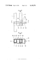
- FIG. 2 is a front view of the supporting means of the embodiment in the backward position usage.
- FIG. 3 is a cross sectional view of FIG. 2 in line III--III.
- FIG. 4 is a perspective view in part of FIG. 1.
- FIG. 5 is a side view of the baby carriage in the folded state.
- numeral 1 indicates a front leg of rectangular pipe which is provided with a front wheel 2 at the bottom.
- Numeral 3 indicates a footstool which is provided at the lower portion of the front leg 1.
- Numeral 4 indicates a supporting rod which is pivotally connected to the top of the front leg 1, by the rotatable joint 5.
- Numeral 6 indicates a rear leg of rectangular pipe which is pivotally attached crosswise to the front leg 1.
- Numeral 7 indicates a rear wheel which is provided at the bottom of the rear leg 7.
- Numeral 8 indicates a elbow rest which is formed by bending the top of the rear leg 6, said elbow rest 8 and said footstools are for a baby who will be seated to look forward in the direction indicated by arrow 40.
- Numeral 9 indicates a handle rod of rectangular pipe which is pivotally connected to a pivoting point 10 of the front leg 1 and the rear leg 6.
- Numeral 11 indicates a joint which foldably connects upper rod 12 and lower rod 13 of the handle rod 9.
- Numeral 9 indicates a slider which is slidably connected to the upper and the lower rods 12, 13, above the joint 11. In the opened state of the baby carriage, the upper rod 12 and the top of the lower rod 13 are inserted through the slider 14 and both rods 12, 13 are held straight. It is possible to fold the upper and lower rods 12, 13 by moving the slider 14 upward to disengage the upper rod 12 from the top of the lower end of rod 13.
- Numeral 15 indicates a supporting member which is fixed to the bottom of the lower rod 13 of the handle rod 9 by pin 15', 15', as shown in FIG. 2.
- the supporting member 15 comprises adjacent parallel, U-shaped portions or compartments, an outside portion 16, a middle portion 17, and an inside portion 18.
- Portions 16 and 18 each have an opening on the side of the supporting means 15 opposite from the opening of portion 17, direction opposite directions alternately, as best shown in FIG. 3.
- the supporting member 15 is formed by bending orthogonally a metallic plate six times so that the three portions 16, 17 and 18 are of rectangular section engageable respectively with the lower rod 13 of the handle rod 9, the rear leg 6, and the front leg 1.
- Numeral 19 indicates an approximately U-shaped turning lock, shown in FIG.
- Rear plate 22 of the turning lock 19 holds the rear leg 6 and the handle rod 9 parallel with each other by extending over the aperture of the middle U-shaped portion 17 of the supporting member 15 into which the rear leg 6 is inserted when the handle rod 9 or push handle is in the forward position, as shown in FIG. 1.
- Front plate 23 of the turning lock 19 holds the front leg 1 and the handle rod 9 parallel with each other by extending over the aperture of the inside U-shaped portion 18 of the supporting member 15 into which the front leg 1 is inserted when the handle rod 9 or push handle is in the backward position.
- Numeral 24 indicates a knob which is provided at the center of a bottom plate 25 of the turning lock 19.
- Numeral 26 indicates a stopper projecting away from the middle portion 17 to restrict the rotation of the front plate 23.
- Numeral 27 indicates a first connecting rod one end of which is pivotally connected to the front leg 1.
- Numeral 28 indicates a second connecting rod one end of which is pivotally connected to the rear leg 6.
- Numeral 29 indicates a third connecting rod one end of which is pivotally connected to the supporting rod 4 by an attachment 30.
- Numeral 31 indicates a linding rod which pivotally connects the other ends of the first, second, and third connecting rods 27, 28, and 29 and contacts with the back surface of the rear leg 6.
- the turning lock 19 is rotated with the knob 24 grasped in the hand until the rear plate 22 pushed from the rear leg 6. Thereafter the handle rod 9 is rotated backward in the direction indicated by Numeral 60 in FIG. 1 with the pivoting point 20 of the front leg 1 and the rear leg 6, as a rotation axis as illustrated by the dotted and dashed lines in FIG. 1. Then, the front leg 1 is inserted into the inside U-shaped portion 18 of the supporting member. Thereafter, the turning lock 19 is rotated around the pivoting pin 21 as a rotation axis until the front plate 23 extends over the aperture of the middle portion 18 of the supporting member 15, to hold the front leg 1 and the handle rod 9 parallel with each other.
- the shifting operation of the push handle 9 from the backward position to the forward position in the direction of the arrows 50 in FIG. 1 can be similarly executed.
- the push handle of the present invention has the following features:
- the structure is very simple because the supporting member 15 is fixedly provided at the bottom of the handle rod 9 and it moves with the handle rod 9 to lock the front leg 1 or rear leg 6 making it unnecessary to provide a complicated structure with the front leg 1 or rear leg 6.
- the slider 14 is slided upwards and the upper rod 12 of the handle rod 9 is folded downwards. Thereafter, a foot is put on the footstool 3 and the elbow rest 8 is pulled up. Then, the front and rear wheels 2 and 7 come close together, the second connecting rod 28 rotates counter-clockwise with the linding rod 31 as its center and pulling down the third connecting rod 29. The third connecting rod 29 rotates the supporting rod 4 backward, and the baby carriage is folded finally as shown in FIG. 5.
- the upper rod 12 of the handle rod 9 is rotated upwards and the upper rod 12 and the lower rod 13 are held straight by the slider 14, and the supporting rod 4 is rotated upward.
- the third connecting rod 29 rotates the first and second connecting rods 27, 28 upwards and it opens the front leg 1 and the rear leg 6.
- the baby carriage is opened finally as shown in FIG. 1.
- the front leg 1, the rear leg 6, and the handle rod 9 may be of circular pipe and the supporting member 15 may have circular sectional portions engageable with the front leg 1, the rear leg 6, and the handle rod 9 of circular pipes.
Landscapes
- Engineering & Computer Science (AREA)
- Chemical & Material Sciences (AREA)
- Combustion & Propulsion (AREA)
- Transportation (AREA)
- Mechanical Engineering (AREA)
- Carriages For Children, Sleds, And Other Hand-Operated Vehicles (AREA)
Applications Claiming Priority (2)
| Application Number | Priority Date | Filing Date | Title |
|---|---|---|---|
| JP51-83355[U] | 1976-06-23 | ||
| JP1976083355U JPS5444916Y2 (en, 2012) | 1976-06-23 | 1976-06-23 |
Publications (1)
| Publication Number | Publication Date |
|---|---|
| US4180276A true US4180276A (en) | 1979-12-25 |
Family
ID=13800118
Family Applications (1)
| Application Number | Title | Priority Date | Filing Date |
|---|---|---|---|
| US05/792,988 Expired - Lifetime US4180276A (en) | 1976-06-23 | 1977-05-02 | Back-to-face reversible push handle of a baby carriage |
Country Status (2)
| Country | Link |
|---|---|
| US (1) | US4180276A (en, 2012) |
| JP (1) | JPS5444916Y2 (en, 2012) |
Cited By (13)
| Publication number | Priority date | Publication date | Assignee | Title |
|---|---|---|---|---|
| FR2500876A1 (fr) * | 1981-02-27 | 1982-09-03 | Peugeot Cycles | Verrou basculant pour grille frontale de chariot de manutention |
| FR2515128A1 (fr) * | 1981-10-26 | 1983-04-29 | Kassai Kk | Mecanisme de changement du sens d'orientation des poignees de pousse d'une poussette de bebe et poussette equipee d'un tel mecanisme |
| EP0090668A1 (en) * | 1982-03-31 | 1983-10-05 | Andrews Maclaren Limited | A collapsible push chair |
| EP0260056A3 (en) * | 1986-09-02 | 1989-06-07 | Aprica Kassai Kabushikikaisha | Baby carriage |
| US5655060A (en) * | 1995-03-31 | 1997-08-05 | Brooks Automation | Time optimal trajectory for cluster tool robots |
| US6059301A (en) * | 1998-01-06 | 2000-05-09 | Skarnulis; Cynthia L. | Baby carriage and adapter handle therefor |
| US20080061524A1 (en) * | 2006-09-11 | 2008-03-13 | Jacob Goldszer | Beach and Accessory Cart and Frame |
| US20090033066A1 (en) * | 2007-07-31 | 2009-02-05 | Graco Children's Products Inc. | Stroller with Foldable Frame and Adjustable Handle |
| US20110248479A1 (en) * | 2010-04-07 | 2011-10-13 | Wonderland Nurserygoods Company Limited | Infant Carrier Apparatus and Its Adjusting Method |
| US8733787B2 (en) * | 2012-10-31 | 2014-05-27 | Goodbaby Child Products Co., Ltd | Baby carriage |
| CN104002851A (zh) * | 2014-05-13 | 2014-08-27 | 东莞市英之堡婴儿用品有限公司 | 一种可折叠手推车车架 |
| US20150151773A1 (en) * | 2012-05-09 | 2015-06-04 | Goodbaby Child Products Co., Ltd | Baby Carriage |
| US10252738B2 (en) * | 2016-06-01 | 2019-04-09 | Greg Diep | Stroller pulling handle system |
Citations (6)
| Publication number | Priority date | Publication date | Assignee | Title |
|---|---|---|---|---|
| US2226000A (en) * | 1939-11-10 | 1940-12-24 | Kroll Samuel | Collapsible carriage |
| US2285700A (en) * | 1940-08-20 | 1942-06-09 | Storkline Furniture Corp | Baby carriage |
| CH252658A (de) * | 1944-11-05 | 1948-01-15 | Mueller Ernst Kg | Kinderwagen. |
| FR1193576A (fr) * | 1958-03-25 | 1959-11-03 | Perfectionnements aux voitures d'enfants | |
| US3873117A (en) * | 1973-01-24 | 1975-03-25 | Giuseppe Perego | Foldable baby carriage construction |
| US3873116A (en) * | 1974-01-25 | 1975-03-25 | Perego Pines Spa | Baby carriage construction |
-
1976
- 1976-06-23 JP JP1976083355U patent/JPS5444916Y2/ja not_active Expired
-
1977
- 1977-05-02 US US05/792,988 patent/US4180276A/en not_active Expired - Lifetime
Patent Citations (6)
| Publication number | Priority date | Publication date | Assignee | Title |
|---|---|---|---|---|
| US2226000A (en) * | 1939-11-10 | 1940-12-24 | Kroll Samuel | Collapsible carriage |
| US2285700A (en) * | 1940-08-20 | 1942-06-09 | Storkline Furniture Corp | Baby carriage |
| CH252658A (de) * | 1944-11-05 | 1948-01-15 | Mueller Ernst Kg | Kinderwagen. |
| FR1193576A (fr) * | 1958-03-25 | 1959-11-03 | Perfectionnements aux voitures d'enfants | |
| US3873117A (en) * | 1973-01-24 | 1975-03-25 | Giuseppe Perego | Foldable baby carriage construction |
| US3873116A (en) * | 1974-01-25 | 1975-03-25 | Perego Pines Spa | Baby carriage construction |
Cited By (17)
| Publication number | Priority date | Publication date | Assignee | Title |
|---|---|---|---|---|
| FR2500876A1 (fr) * | 1981-02-27 | 1982-09-03 | Peugeot Cycles | Verrou basculant pour grille frontale de chariot de manutention |
| FR2515128A1 (fr) * | 1981-10-26 | 1983-04-29 | Kassai Kk | Mecanisme de changement du sens d'orientation des poignees de pousse d'une poussette de bebe et poussette equipee d'un tel mecanisme |
| EP0090668A1 (en) * | 1982-03-31 | 1983-10-05 | Andrews Maclaren Limited | A collapsible push chair |
| WO1983003393A1 (en) * | 1982-03-31 | 1983-10-13 | Al-Sheikh, Abdelraouf, Mohamad, Sami | A collapsible push chair |
| EP0260056A3 (en) * | 1986-09-02 | 1989-06-07 | Aprica Kassai Kabushikikaisha | Baby carriage |
| US5655060A (en) * | 1995-03-31 | 1997-08-05 | Brooks Automation | Time optimal trajectory for cluster tool robots |
| US6059301A (en) * | 1998-01-06 | 2000-05-09 | Skarnulis; Cynthia L. | Baby carriage and adapter handle therefor |
| US20080061524A1 (en) * | 2006-09-11 | 2008-03-13 | Jacob Goldszer | Beach and Accessory Cart and Frame |
| US20090033066A1 (en) * | 2007-07-31 | 2009-02-05 | Graco Children's Products Inc. | Stroller with Foldable Frame and Adjustable Handle |
| US8128119B2 (en) * | 2007-07-31 | 2012-03-06 | Graco Children's Products Inc. | Stroller with foldable frame and adjustable handle |
| US20110248479A1 (en) * | 2010-04-07 | 2011-10-13 | Wonderland Nurserygoods Company Limited | Infant Carrier Apparatus and Its Adjusting Method |
| US8622404B2 (en) * | 2010-04-07 | 2014-01-07 | Wonderland Nurserygoods Company Limited | Infant carrier apparatus and its adjusting method |
| US20150151773A1 (en) * | 2012-05-09 | 2015-06-04 | Goodbaby Child Products Co., Ltd | Baby Carriage |
| US9168939B2 (en) * | 2012-05-09 | 2015-10-27 | Goodbaby Child Products Co., Ltd | Baby carriage |
| US8733787B2 (en) * | 2012-10-31 | 2014-05-27 | Goodbaby Child Products Co., Ltd | Baby carriage |
| CN104002851A (zh) * | 2014-05-13 | 2014-08-27 | 东莞市英之堡婴儿用品有限公司 | 一种可折叠手推车车架 |
| US10252738B2 (en) * | 2016-06-01 | 2019-04-09 | Greg Diep | Stroller pulling handle system |
Also Published As
| Publication number | Publication date |
|---|---|
| JPS531761U (en, 2012) | 1978-01-10 |
| JPS5444916Y2 (en, 2012) | 1979-12-24 |
Similar Documents
| Publication | Publication Date | Title |
|---|---|---|
| US4180276A (en) | Back-to-face reversible push handle of a baby carriage | |
| US4832361A (en) | Foldable baby carriage | |
| US4317581A (en) | Baby carriage | |
| US4828281A (en) | Convertible car seat stroller | |
| JP4937473B2 (ja) | ベビーカーの折り畳み操作装置 | |
| KR880003567Y1 (ko) | 유모차 | |
| US4253546A (en) | Hand truck | |
| US20170247043A1 (en) | Stroller frame | |
| JPH0775984B2 (ja) | ベビーカーのリクライニング若しくは倒伏機構 | |
| JPS591622B2 (ja) | 乳母車の押し棒の方向変更機構 | |
| CN210653267U (zh) | 一种便于折叠的童车骨架 | |
| TW202241747A (zh) | 車架與嬰兒車 | |
| CN210822428U (zh) | 一种婴儿车的可换向座位 | |
| CN210653254U (zh) | 一种童车骨架 | |
| CN207790800U (zh) | 一种婴儿车 | |
| CN216102328U (zh) | 一种新型儿童推车 | |
| CN210526629U (zh) | 一种新型的车架折叠机构 | |
| KR960003727Y1 (ko) | 유모차 | |
| JPS6238851Y2 (en, 2012) | ||
| CN106314514A (zh) | 可折叠的婴儿车车架 | |
| JPS5832065B2 (ja) | 乳母車 | |
| JP2001204593A (ja) | 幼児背負い具 | |
| JPH0114216Y2 (en, 2012) | ||
| JPS6037848Y2 (ja) | スライド機構付き折りたたみシ−ト装置 | |
| JPS6134200Y2 (en, 2012) |
Legal Events
| Date | Code | Title | Description |
|---|---|---|---|
| AS | Assignment |
Owner name: APRICA KASSAI KABUSHIKI KAISHA 16-1, HIGASHISHIMIZ Free format text: CHANGE OF NAME;ASSIGNOR:KASSAI KABUSHIKI KAISHA;REEL/FRAME:004540/0899 Effective date: 19850801 |