US4055625A - Method of treatment of a mixture of air and at least partially radioactive rare gases - Google Patents
Method of treatment of a mixture of air and at least partially radioactive rare gases Download PDFInfo
- Publication number
- US4055625A US4055625A US05/592,949 US59294975A US4055625A US 4055625 A US4055625 A US 4055625A US 59294975 A US59294975 A US 59294975A US 4055625 A US4055625 A US 4055625A
- Authority
- US
- United States
- Prior art keywords
- mixture
- xenon
- oxygen
- krypton
- hydrogen
- Prior art date
- Legal status (The legal status is an assumption and is not a legal conclusion. Google has not performed a legal analysis and makes no representation as to the accuracy of the status listed.)
- Expired - Lifetime
Links
Images


Classifications
-
- C—CHEMISTRY; METALLURGY
- C01—INORGANIC CHEMISTRY
- C01B—NON-METALLIC ELEMENTS; COMPOUNDS THEREOF; METALLOIDS OR COMPOUNDS THEREOF NOT COVERED BY SUBCLASS C01C
- C01B23/00—Noble gases; Compounds thereof
-
- F—MECHANICAL ENGINEERING; LIGHTING; HEATING; WEAPONS; BLASTING
- F25—REFRIGERATION OR COOLING; COMBINED HEATING AND REFRIGERATION SYSTEMS; HEAT PUMP SYSTEMS; MANUFACTURE OR STORAGE OF ICE; LIQUEFACTION SOLIDIFICATION OF GASES
- F25J—LIQUEFACTION, SOLIDIFICATION OR SEPARATION OF GASES OR GASEOUS OR LIQUEFIED GASEOUS MIXTURES BY PRESSURE AND COLD TREATMENT OR BY BRINGING THEM INTO THE SUPERCRITICAL STATE
- F25J3/00—Processes or apparatus for separating the constituents of gaseous or liquefied gaseous mixtures involving the use of liquefaction or solidification
- F25J3/02—Processes or apparatus for separating the constituents of gaseous or liquefied gaseous mixtures involving the use of liquefaction or solidification by rectification, i.e. by continuous interchange of heat and material between a vapour stream and a liquid stream
- F25J3/0228—Processes or apparatus for separating the constituents of gaseous or liquefied gaseous mixtures involving the use of liquefaction or solidification by rectification, i.e. by continuous interchange of heat and material between a vapour stream and a liquid stream characterised by the separated product stream
- F25J3/028—Processes or apparatus for separating the constituents of gaseous or liquefied gaseous mixtures involving the use of liquefaction or solidification by rectification, i.e. by continuous interchange of heat and material between a vapour stream and a liquid stream characterised by the separated product stream separation of noble gases
-
- G—PHYSICS
- G21—NUCLEAR PHYSICS; NUCLEAR ENGINEERING
- G21F—PROTECTION AGAINST X-RADIATION, GAMMA RADIATION, CORPUSCULAR RADIATION OR PARTICLE BOMBARDMENT; TREATING RADIOACTIVELY CONTAMINATED MATERIAL; DECONTAMINATION ARRANGEMENTS THEREFOR
- G21F9/00—Treating radioactively contaminated material; Decontamination arrangements therefor
- G21F9/02—Treating gases
-
- F—MECHANICAL ENGINEERING; LIGHTING; HEATING; WEAPONS; BLASTING
- F25—REFRIGERATION OR COOLING; COMBINED HEATING AND REFRIGERATION SYSTEMS; HEAT PUMP SYSTEMS; MANUFACTURE OR STORAGE OF ICE; LIQUEFACTION SOLIDIFICATION OF GASES
- F25J—LIQUEFACTION, SOLIDIFICATION OR SEPARATION OF GASES OR GASEOUS OR LIQUEFIED GASEOUS MIXTURES BY PRESSURE AND COLD TREATMENT OR BY BRINGING THEM INTO THE SUPERCRITICAL STATE
- F25J2205/00—Processes or apparatus using other separation and/or other processing means
- F25J2205/82—Processes or apparatus using other separation and/or other processing means using a reactor with combustion or catalytic reaction
-
- F—MECHANICAL ENGINEERING; LIGHTING; HEATING; WEAPONS; BLASTING
- F25—REFRIGERATION OR COOLING; COMBINED HEATING AND REFRIGERATION SYSTEMS; HEAT PUMP SYSTEMS; MANUFACTURE OR STORAGE OF ICE; LIQUEFACTION SOLIDIFICATION OF GASES
- F25J—LIQUEFACTION, SOLIDIFICATION OR SEPARATION OF GASES OR GASEOUS OR LIQUEFIED GASEOUS MIXTURES BY PRESSURE AND COLD TREATMENT OR BY BRINGING THEM INTO THE SUPERCRITICAL STATE
- F25J2210/00—Processes characterised by the type or other details of the feed stream
- F25J2210/40—Air or oxygen enriched air, i.e. generally less than 30mol% of O2
-
- F—MECHANICAL ENGINEERING; LIGHTING; HEATING; WEAPONS; BLASTING
- F25—REFRIGERATION OR COOLING; COMBINED HEATING AND REFRIGERATION SYSTEMS; HEAT PUMP SYSTEMS; MANUFACTURE OR STORAGE OF ICE; LIQUEFACTION SOLIDIFICATION OF GASES
- F25J—LIQUEFACTION, SOLIDIFICATION OR SEPARATION OF GASES OR GASEOUS OR LIQUEFIED GASEOUS MIXTURES BY PRESSURE AND COLD TREATMENT OR BY BRINGING THEM INTO THE SUPERCRITICAL STATE
- F25J2215/00—Processes characterised by the type or other details of the product stream
- F25J2215/34—Krypton
-
- F—MECHANICAL ENGINEERING; LIGHTING; HEATING; WEAPONS; BLASTING
- F25—REFRIGERATION OR COOLING; COMBINED HEATING AND REFRIGERATION SYSTEMS; HEAT PUMP SYSTEMS; MANUFACTURE OR STORAGE OF ICE; LIQUEFACTION SOLIDIFICATION OF GASES
- F25J—LIQUEFACTION, SOLIDIFICATION OR SEPARATION OF GASES OR GASEOUS OR LIQUEFIED GASEOUS MIXTURES BY PRESSURE AND COLD TREATMENT OR BY BRINGING THEM INTO THE SUPERCRITICAL STATE
- F25J2215/00—Processes characterised by the type or other details of the product stream
- F25J2215/36—Xenon
-
- F—MECHANICAL ENGINEERING; LIGHTING; HEATING; WEAPONS; BLASTING
- F25—REFRIGERATION OR COOLING; COMBINED HEATING AND REFRIGERATION SYSTEMS; HEAT PUMP SYSTEMS; MANUFACTURE OR STORAGE OF ICE; LIQUEFACTION SOLIDIFICATION OF GASES
- F25J—LIQUEFACTION, SOLIDIFICATION OR SEPARATION OF GASES OR GASEOUS OR LIQUEFIED GASEOUS MIXTURES BY PRESSURE AND COLD TREATMENT OR BY BRINGING THEM INTO THE SUPERCRITICAL STATE
- F25J2215/00—Processes characterised by the type or other details of the product stream
- F25J2215/42—Nitrogen or special cases, e.g. multiple or low purity N2
-
- F—MECHANICAL ENGINEERING; LIGHTING; HEATING; WEAPONS; BLASTING
- F25—REFRIGERATION OR COOLING; COMBINED HEATING AND REFRIGERATION SYSTEMS; HEAT PUMP SYSTEMS; MANUFACTURE OR STORAGE OF ICE; LIQUEFACTION SOLIDIFICATION OF GASES
- F25J—LIQUEFACTION, SOLIDIFICATION OR SEPARATION OF GASES OR GASEOUS OR LIQUEFIED GASEOUS MIXTURES BY PRESSURE AND COLD TREATMENT OR BY BRINGING THEM INTO THE SUPERCRITICAL STATE
- F25J2220/00—Processes or apparatus involving steps for the removal of impurities
- F25J2220/40—Separating high boiling, i.e. less volatile components from air, e.g. CO2, hydrocarbons
-
- Y—GENERAL TAGGING OF NEW TECHNOLOGICAL DEVELOPMENTS; GENERAL TAGGING OF CROSS-SECTIONAL TECHNOLOGIES SPANNING OVER SEVERAL SECTIONS OF THE IPC; TECHNICAL SUBJECTS COVERED BY FORMER USPC CROSS-REFERENCE ART COLLECTIONS [XRACs] AND DIGESTS
- Y02—TECHNOLOGIES OR APPLICATIONS FOR MITIGATION OR ADAPTATION AGAINST CLIMATE CHANGE
- Y02P—CLIMATE CHANGE MITIGATION TECHNOLOGIES IN THE PRODUCTION OR PROCESSING OF GOODS
- Y02P20/00—Technologies relating to chemical industry
- Y02P20/151—Reduction of greenhouse gas [GHG] emissions, e.g. CO2
-
- Y—GENERAL TAGGING OF NEW TECHNOLOGICAL DEVELOPMENTS; GENERAL TAGGING OF CROSS-SECTIONAL TECHNOLOGIES SPANNING OVER SEVERAL SECTIONS OF THE IPC; TECHNICAL SUBJECTS COVERED BY FORMER USPC CROSS-REFERENCE ART COLLECTIONS [XRACs] AND DIGESTS
- Y10—TECHNICAL SUBJECTS COVERED BY FORMER USPC
- Y10S—TECHNICAL SUBJECTS COVERED BY FORMER USPC CROSS-REFERENCE ART COLLECTIONS [XRACs] AND DIGESTS
- Y10S62/00—Refrigeration
- Y10S62/923—Inert gas
- Y10S62/925—Xenon or krypton
Definitions
- This invention relates to the treatments to which mixtures of air and rare gases are subjected and more particularly the gaseous effluents derived from reprocessing of irradiated nuclear fuels, a further object of such treatments being to recover the xenon contained in these mixtures.
- the gaseous effluents which are produced by irradiated fuel reprocessing plants and to which the invention is more particularly applicable are essentially constituted by air containing at least rare gases such as xenon and krypton and usually water vapor, carbon dioxide gas and also nitrogen oxides, the presence of which is due to the dissolution of the fuels in a nitric acid medium.
- cryogenic distillation is understood to mean in each case that the mixture considered is brought to the liquefied state no later than at the level of a boiler provided at the bottom of a column in which the distillation takes place.
- the xenon which can finally be produced by these methods is free from any radioactive character and well-suited to all the usual industrial uses of this rare gas whereas the period of decay of radioactive krypton is much too long to make its presence acceptable.
- the present invention is directed to a method which makes it possible to overcome the disadvantages of methods which have been known up to the present time, this being achieved by replacing the nitrogen or a nitrogen-oxygen mixture by oxygen in the process of concentration by distillation.
- this being achieved by replacing the nitrogen or a nitrogen-oxygen mixture by oxygen in the process of concentration by distillation.
- the presence of oxygen does not give rise to any insurmountable danger despite the residence times which are necessary in distillation operations.
- the invention is thus primarily concerned with a method of treatment of a mixture of air and rare gases including xenon and krypton in particular which are at least partially radioactive and especially gaseous effluents derived from the reprocessing of irradiated fuels.
- the invention essentially comprises a stage of concentration of the rare gases in solution in liquid oxygen by cryogenic distillation of the light gases and especially nitrogen from the liquefied mixture. These distillates can be processed with a view to recovering the nitrogen and recycling this latter on the shearing machine which serves to cut the fuels in the reprocessing plant.
- the method preferably comprises in addition a stage of separation of the rare gases by catalytic combustion of oxygen with hydrogen and removal of the water which is formed followed by a stage of recovery of xenon by cryogenic distillation of the other rare gas or gases.
- the invention is also concerned with a method of treatment of effluent gases derived from the reprocessing of irradiated nuclear fuels constituted by a gaseous mixture containing at least xenon and krypton which is radioactive in air.
- the method essentially comprises in succession a first stage of purification of the gaseous mixture with a view to removing any impurities such as the nitrogen oxides, carbon dioxide gas, water vapor, and more particularly the hydrocarbons, a second stage of concentration of the xenon and the krypton of the gaseous mixture, said concentration being carried out in solution in liquid oxygen by distillation of the light gases and mainly nitrogen from the liquefied mixture, a third stage of separation of the xenon and the krypton by catalytic combustion of the oxygen of the mixture previously obtained with hydrogen and removal of the water which is formed, and a fourth stage of recovery of the xenon by cryogenic distillation of the mixture of xenon and krypton.
- the catalytic combustion of oxygen which preferably forms part of the method according to the invention can take place in the presence of an excess quantity of hydrogen.
- One of the advantages of this combustion lies in the fact that it facilitates the final stage of xenon recovery.
- the distillation of the xenon-krypton mixture takes place in the absence of oxygen.
- the greater part is preferably eliminated, especially by trapping of the krypton and the xenon by cold production, the hydrogen which remains in the mixture distils more readily with krypton than would be the case if oxygen were employed or even more readily than is the case with the use of nitrogen in conventional methods.
- the fact that the xenon-krypton-hydrogen mixture has a reducing action is advantageous in one preferred mode of execution of the method in which said mixture is subjected to a complementary catalytic treatment for removing any traces of nitrogen oxides.
- the catalytic combustion of oxygen takes place in the presence of a slight excess quantity of hydrogen in a gas mixture which mainly contains krypton and xenon derived from recycling of the gases at the end of processing.
- the method in accordance with this alternative embodiment permits dilution of the oxygen in the mixture which circulates within the reactor and this dilution limits the heat build-up of said reactor.
- the problem of heat build-up in a reactor is of primary importance: if the dilution of oxygen circulating within the reactor is not carried out, there is a considerable temperature rise due to the exothermic reaction of hydrogen with oxygen to form water.
- the temperature rise due to the exothermic reaction of combustion of hydrogen in oxygen is approximately 160° per one volume percent of oxygen in the case of combustion in hydrogen and would attain 220° C per one volume percent of oxygen in the case of combustion in a krypton-xenon mixture.
- the object of this alternative embodiment is to provide a loop system for the recirculation of gases discharged from the reactor with a view on the one hand to operating with a slight excess quantity of hydrogen only at the reactor outlet and on the other hand with a view to strongly diluting the oxygen which passes through said reactor with inert gases, namely krypton and xenon; the non-recycled fraction of gases obtained at the reactor outlet is continuously returned after removal of water into a cryogenic distillation column in order to ensure separation and recovery of the xenon in said column.
- the stage of concentration by distillation of the light gases and mainly nitrogen can take place in liquid oxygen in accordance with the invention, in spite of the radioactive medium. It is even a remarkable fact that the presence of a large quantity of oxygen, as is likely to be the case if the preliminary operations provided in known processes for the removal of oxygen are completely suppressed, offers the advantage of promoting efficient operation at the level of the concentration by ensuring enhanced solubilization of the xenon and the krypton and facilitating complete removal of nitrogen, which also proves beneficial in the final stage of xenon recovery.
- the mixture of air and rare gases it is preferable to subject the mixture of air and rare gases to purification prior to the concentration stage with a view in particular to removing any hydrocarbons which may be present.
- This purification process can also be more complete and make it possible in particular to remove the nitrogen oxides, the carbon dioxide gas and the water vapor as in the methods of the prior art for the treatment of gaseous effluents derived from reprocessing of nuclear fuels.
- Installations of this type comprise in particular catalytic reactors and cryogenic distillation columns together with all their known ancillary equipments which are connected by means of pipes for the circulation of the different products and so arranged as to permit the successive operations of the method defined in the foregoing.
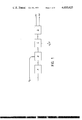
- FIG. 1 illustrates diagrammatically the sequence of operations involved in the method described
- FIGS. 2a, 2b and 2c are schematic diagrams which show the installation employed and the circulation of the products between the different stages;
- FIG. 3 shows an alternative embodiment of the invention which is concerned with the catalytic combustion of oxygen.
- the method according to the invention is applied to the treatment of gaseous effluents derived from a nuclear fuel reprocessing plant. More particularly, the treated effluent comes partly from a workshop for cutting irradiated fuel elements and partly from a workshop for the dissolution of the fuel in nitric acid.
- the method applies more generally to the recovery of xenon in a gas mixture.
- the effluent is supplied to the installation as shown diagrammatically in FIG. 1 from a workshop in which the iodine which may be present therein is adsorbed and removed. Said effluent is then made up of air (97 to 99 volume %) containing nitrogen protoxide N 2 O (1 to 3 %), traces of CO 2 , NO 3 H, NO, NO 2 , water vapor at saturation, xenon (550 volumes per million approximately) and krypton (50 volumes per million approximately), this latter being partly in the form of radioactive Kr 85.
- the installation mainly comprises four successive treatment units which make it possible respectively to carry out the four following stages of operation, in this order:
- the purification stage which consists in freeing the treated effluent from the impurities contained therein and especially hydrocarbons so as to obtain a mixture consisting of air which practically no longer contains xenon and krypton.
- the concentration stage which mainly consists of cryogenic distillation of the purified mixture, this distillation being carried out so as to remove practically the entire quantity of nitrogen contained in the mixture as well as the greater part of the oxygen and to collect a concentrated mixture of xenon and krypton in oxygen.
- the separated mixture of xenon, krypton and hydrogen is subjected to a second cryogenic distillation operation so as to remove the krypton and hydrogen and to collect pure xenon.
- the treated gaseous effluent passes into scrubbing towers (not shown) comprising a sodium hydroxide scrubbing tower in which the effluent is freed from CO 2 , NO and NO 2 , followed by a water scrubbing tower in which the entrained sodium hydroxide and ammonia are removed.
- scrubbing towers (not shown) comprising a sodium hydroxide scrubbing tower in which the effluent is freed from CO 2 , NO and NO 2 , followed by a water scrubbing tower in which the entrained sodium hydroxide and ammonia are removed.
- the effluent then passes through the heater E 1 in which its temperature is increased to approximately 500° C, then into the reaction vessel A 1 in which a catalyst (platinum, for example) decomposes the hydrocarbons to form CO 2 and H 2 O whilst another catalyst (rhodium, for example) decomposes the nitrogen protoxide N 2 O to N 2 and O 2 .
- a catalyst platinum, for example
- platinum platinum, for example
- Said mixture is cooled by exchange with water within the cooling unit E 2 , then compressed to approximately 8 atm. abs. within the compressor C 1 .
- the mixture is again cooled within the unit E 3 in which a certain condensation of water takes place.
- the water is collected in the separator B 1 and removed.
- the compressed mixture obtained is dried by passing through a molecular sieve within one of the two adsorbers T 1 and T 2 which are placed in parallel. Traces of CO 2 are also retained in this adsorption. These two adsorbers are subjected periodically and alternately to regeneration by heating and circulating a fraction of the treated gas mixture which can then be recycled to the inlet of the purification unit.
- the cooler E 4 reduces the temperature of the treated gas mixture to a value of the order of 20° C and the filter F 1 retains the sieve particles which may have been entrained.
- the mixture which has just been purified is admitted into the concentration unit in which it passes first into the heat exchanger E 5 and is cooled to a temperature in the vicinity of the dew-point before being admitted into the bottom of the distillation column K 1 .
- the distillation column operates at a pressure of approximately 1.5 atm. abs.
- the lower portion of the colunn K 1 is constituted by a boiler in which the liquefaction of the gas mixture provides the greater part of the heating which is necessary for the operation of the column.
- An electric device for auxiliary heating is installed within the boiler itself.
- a purge at the top of the vaporizer permits periodic discharge of non-liquefiable gases, namely helium in particular.
- the pressure within the boiler is 8 atm. abs.
- the liquefied mixture is withdrawn from the bottom of the column and passed into the central portion of the colunn via one of two alumina filters T 3 and T 4 which are periodically subjected both to alternate operation and to regeneration and remove the final traces of any hydrocarbons which may be present.
- the colunn K 1 ensures the removal of part of the oxygen and the entire quantity of nitrogen which can be purified and recycled to the head of the plant.
- the column also carries out the concentration of the krypton and xenon in solution in liquid oxygen. There is withdrawn from the top of the column a decontaminated mixture which contains oxygen and argon in addition to nitrogen. This mixture is heated within the heat exchanger E 5 in counterflow to the mixture which is fed into the column. There is withdrawn from the boiler of the column a concentrated mixture of krypton and xenon in oxygen and this latter passes into a heat exchanger E 6 which ensures vaporization and reheating of the mixture.
- the column K 1 can also be coupled if necessary to ozone traps T 5 and T 6 . Connections are provided at the level of the boiler of the column for continuously withdrawing a fraction of the concentrated liquefied mixture, for passing said mixture into a heat exchanger E 13 , then into either of the two elements which effects the dissociation of the ozone and operates periodically in alternate sequence, for then returning the mixture to the bottom of the column through the countercurrent exchanger E 13 .
- the concentrated mixture of krypton and xenon in oxygen which is obtained at the outlet of the concentration unit is diluted in a hydrogen loop, the flow rate being such as to obtain an oxygen content which is lower than 2 % within the reaction vessel A 2 .
- the mixture is then reheated within the heater E 7 to a temperature of the order of 100° C.
- the gas mixture is then introduced into a reaction vessel A 2 in which there takes place a catalytic combustion of oxygen with hydrogen on a palladium catalyst, for example of the "Deoxo" type.
- a palladium catalyst for example of the "Deoxo" type.
- Another catalyst bed rhodium, for example
- the gas mixture passes into the cooler E 8 in which it is cooled and the condensed water is removed at B 2 .
- the gas mixture which is withdrawn at the exit of a fan C 3 is made up of xenon and krypton, hydrogen and water vapor.
- a three-way valve 100 is placed on the exit side of the fan C 3 . That portion which is not recycled through the pipe 101 then passes into either of two assemblies which operate periodically in alternate sequence and each comprise a heat exchanger E 9 or E 10 in which the water vapor is removed by low-temperature deposition, followed by a freezer F 2 or F 3 in which the xenon and the krypton are retained at a temperature of approximately -180° C.
- the heat exchangers E 9 and E 10 are cooled by the cold nitrogen which is withdrawn at the nitrogen outlet of the condenser at the head of the column K 1 whilst the freezers F 2 and F 3 are cooled by circulation of liquid nitrogen.
- Recovery of the krypton-xenon mixture is carried out alternately from one of the freezers F 2 and F 3 which is isolated from the circuit C 3 by heating said freezer. This heating causes sublimation of the xenon and krypton deposit.
- the water which is trapped in the heat exchanger E 9 or E 10 is heated and removed at the same time.
- the krypton-xenon-hydrogen gas mixture is transferred into the xenon recovery unit. Said mixture is admitted under a pressure of 4 atm. abs. approximately into the central portion of a column K 2 in which distillation of the krypton takes place.
- a condenser cooled by an argon bath which is in turn cooled by a circulation of liquid nitrogen within the heat exchanger E 14 ensures column reflux. Heating of the boiler is carried out by means of a heater E 15 .
- the partly radioactive distilled krypton which may still contain hydrogen is withdrawn at the head of the column K 2 .
- Marketable xenon in the pure state is withdrawn from the bottom end of the column and heated in a heat exchanger E 11 .
- the xenon is available at the outlet of the installation at 4 atm. abs. and at room temperature.
- FIG. 3 The structure which is illustrated in FIG. 3 constitutes an alternative embodiment of the device shown in FIG. 2c and described earlier.
- the device shown on the upstream side of this single figure is the same as the device which is employed in the installation of FIG. 2c and shown in FIGS. 2a and 2b.
- the device illustrated in FIG. 3 is essentially concerned with the reaction vessel which is employed for removing oxygen from the mixture derived from the prior equipment, that is to say the distillation column employed for obtaining the oxygen-krypton-xenon mixture. Said mixture (approximately 90 % oxygen) is admitted via the heat exchanger E 6 which is shown in FIG. 2b.
- the device comprises a heater-exchanger E 7 , a catalytic combustion reactor A 2 , a heat exchanger E 8 , a vessel B 2 in which the water is collected, a fan C 3 , a branch pipe 100 which directs part of the exit gases from the reaction vessel A 2 to the pipe 102 which is connected to a hydrogen supply by means of the line 104, the other part of the exit gases being directed via the line 106 to the distillation column K 2 through one of the two heat exchangers E 9 and E 10 .
- the concentrated mixture of krypton and xenon in oxygen which is obtained at the exit of the concentration unit shown in FIG. 2b is diluted within the krypton and xenon loop circuit constituted by the pipe 102, the heat exchanger E 7 , the reaction vessel A 2 , the heat exchanger E 8 , the vessel B 2 , the fan C 3 and the pipe 101.
- the flow rate of krypton and of xenon is such that the oxygen content within the reaction vessel A 2 is lower than 2 %.
- the hydrogen is injected via the line 104 in order to maintain a slight excess quantity of this gas at the exit 110 of the reaction vessel A 2 (in contrast to FIG. 2c in which the flow rate of injected hydrogen resulted in a considerable excess quantity of hydrogen).
- the mixture derived from the heat exchanger E 6 after addition of the mixture consisting mainly of krypton and xenon supplied through the pipe 102 is heated to 100° C within the heat exchanger E 7 , then introduced into the reaction vessel A 2 in which is carried out the catalytic reaction of oxygen with hydrogen on a catalyst of known type designated as "Deoxo"; another type of catalyst can also be incorporated in the reaction vessel A 2 in order to remove any possible traces of nitrogen oxides NO and NO 2 .
- the gas mixture passes into the cooler E 8 and is cooled within this latter.
- the condensed water is removed within the vessel B 2 .
- the gas mixture withdrawn from the exit of the fan C 3 and consisting of xenon, krypton, a small quantity of hydrogen and a small quantity of water vapor, is directed partly through the pipe 101 into the pipe 102 and partly through the pipe 106 into one of the heat exchangers E 9 or E 10 .
- These two heat exchangers E 9 and E 10 are connected in parallel in order to permit the alternate use of either one heat exchanger or the other whilst the exchanger which is not in use can be regenerated.
- a condenser 108 cooled by an argon bath which is in turn cooled by a circulation of liquid nitrogen within the heat exchanger E 14 ensures column reflux. Heating of the boiler is carried out by means of the heater E 15 .
- the distilled krypton is withdrawn at the head of the column K 2 .
- Marketable xenon in the pure state is withdrawn from the bottom of the column K 2 and reheated in a heater E 11 .
- the xenon is available at the exit of the installation at four atmospheres and at room temperature.
- the device of FIG. 3 permits a more simple installation and enhanced safety.
- the hydrogen which has constituted the main carrier gas in the reaction vessel A 2 is replaced by krypton and xenon which are inert gases.
- the loop-system recirculation of krypton and xenon within the reaction vessel A 2 reduces heat build-up within the reaction vessel A 2 and dilutes the oxygen which is introduced.
- the rate of feed of the final column K 2 is uniform since the operation can be wholly continuous.
Applications Claiming Priority (4)
| Application Number | Priority Date | Filing Date | Title |
|---|---|---|---|
| FR7426520A FR2280954B1 (fr) | 1974-07-31 | 1974-07-31 | Procede de traitement de melanges d'air et de gaz rares au moins partiellement radio-actifs |
| FR74.26520 | 1974-07-31 | ||
| FR7511965A FR2308169A2 (fr) | 1975-04-17 | 1975-04-17 | Procede de traitement de melange d'air et de gaz rare eventuellement radio-actif |
| FR75.11965 | 1975-04-17 |
Publications (1)
| Publication Number | Publication Date |
|---|---|
| US4055625A true US4055625A (en) | 1977-10-25 |
Family
ID=26218457
Family Applications (1)
| Application Number | Title | Priority Date | Filing Date |
|---|---|---|---|
| US05/592,949 Expired - Lifetime US4055625A (en) | 1974-07-31 | 1975-07-03 | Method of treatment of a mixture of air and at least partially radioactive rare gases |
Country Status (8)
| Country | Link |
|---|---|
| US (1) | US4055625A (nl) |
| JP (1) | JPS5144799A (nl) |
| DE (1) | DE2533847A1 (nl) |
| ES (1) | ES439878A1 (nl) |
| GB (1) | GB1509581A (nl) |
| IT (1) | IT1041338B (nl) |
| NL (1) | NL7508382A (nl) |
| SE (1) | SE407993B (nl) |
Cited By (8)
| Publication number | Priority date | Publication date | Assignee | Title |
|---|---|---|---|---|
| US4206073A (en) * | 1977-03-16 | 1980-06-03 | Hoechst Aktiengesellschaft | Process for separating volatile, radioactive substances obtained in the reprocessing of nuclear fuel |
| WO1981000413A1 (en) * | 1979-08-06 | 1981-02-19 | Science Applic Inc | Method for treating a nuclear process off-gas stream |
| US4277363A (en) * | 1978-08-11 | 1981-07-07 | Commissariat A L'energie Atomique | Method for processing a mixture of air and rare gases, especially xenon and krypton |
| US4447353A (en) * | 1979-08-06 | 1984-05-08 | The United States Of America As Represented By The United States Department Of Energy | Method for treating a nuclear process off-gas stream |
| US5204075A (en) * | 1991-05-30 | 1993-04-20 | The Boc Group, Inc. | Process for the purification of the inert gases |
| US5567887A (en) * | 1994-03-10 | 1996-10-22 | Texas Instruments Incorporated | Anhydrous ammonia gas sampler and concentration system |
| US20030206849A1 (en) * | 2002-05-01 | 2003-11-06 | Griffiths John Louis | Krypton and xenon recovery system |
| US20110094873A1 (en) * | 2003-03-04 | 2011-04-28 | Taiyo Nippon Sanso Corporation | Oxygen isotope concentration method |
Families Citing this family (2)
| Publication number | Priority date | Publication date | Assignee | Title |
|---|---|---|---|---|
| DE2611833C2 (de) * | 1976-03-19 | 1985-12-05 | Linde Ag, 6200 Wiesbaden | Verfahren zur Abtrennung von radioaktivem Krypton und Xenon aus Abgasen aus Kernbrennstoff-Wiederaufbereitungsanlagen oder Kernreaktoren |
| DE3002649A1 (de) * | 1980-01-25 | 1981-08-06 | Linde Ag, 6200 Wiesbaden | Verfahren und vorrichtung zur gewinnung von so (pfeil abwaerts)2(pfeil abwaerts) |
Citations (8)
| Publication number | Priority date | Publication date | Assignee | Title |
|---|---|---|---|---|
| US2962868A (en) * | 1956-02-17 | 1960-12-06 | Air Reduction | Method of concentrating kryptonxenon |
| US3173778A (en) * | 1961-01-05 | 1965-03-16 | Air Prod & Chem | Separation of gaseous mixtures including argon |
| US3181306A (en) * | 1961-01-11 | 1965-05-04 | Air Prod & Chem | Argon separation |
| US3222879A (en) * | 1962-02-27 | 1965-12-14 | Stoklosinski Roman | Recovery of krypton and xenon from air separation plants |
| US3596471A (en) * | 1968-03-15 | 1971-08-03 | Messer Griesheim Gmbh | Process for recovering a mixture of krypton and xenon from air with argon stripper |
| US3748864A (en) * | 1969-01-21 | 1973-07-31 | Airco Inc | Process for recovery and containment of radioactive gases |
| US3751934A (en) * | 1970-11-10 | 1973-08-14 | K Frischbier | Concentrating krypton and xenon in air separation by liquid oxygen wash |
| US3944646A (en) * | 1972-05-11 | 1976-03-16 | Union Carbide Corporation | Radioactive krypton gas separation |
-
1975
- 1975-06-30 GB GB27601/75A patent/GB1509581A/en not_active Expired
- 1975-07-03 US US05/592,949 patent/US4055625A/en not_active Expired - Lifetime
- 1975-07-14 NL NL7508382A patent/NL7508382A/nl not_active Application Discontinuation
- 1975-07-23 IT IT68919/75A patent/IT1041338B/it active
- 1975-07-25 SE SE7508468A patent/SE407993B/xx unknown
- 1975-07-29 DE DE19752533847 patent/DE2533847A1/de not_active Withdrawn
- 1975-07-31 JP JP50094116A patent/JPS5144799A/ja active Pending
- 1975-07-31 ES ES439878A patent/ES439878A1/es not_active Expired
Patent Citations (8)
| Publication number | Priority date | Publication date | Assignee | Title |
|---|---|---|---|---|
| US2962868A (en) * | 1956-02-17 | 1960-12-06 | Air Reduction | Method of concentrating kryptonxenon |
| US3173778A (en) * | 1961-01-05 | 1965-03-16 | Air Prod & Chem | Separation of gaseous mixtures including argon |
| US3181306A (en) * | 1961-01-11 | 1965-05-04 | Air Prod & Chem | Argon separation |
| US3222879A (en) * | 1962-02-27 | 1965-12-14 | Stoklosinski Roman | Recovery of krypton and xenon from air separation plants |
| US3596471A (en) * | 1968-03-15 | 1971-08-03 | Messer Griesheim Gmbh | Process for recovering a mixture of krypton and xenon from air with argon stripper |
| US3748864A (en) * | 1969-01-21 | 1973-07-31 | Airco Inc | Process for recovery and containment of radioactive gases |
| US3751934A (en) * | 1970-11-10 | 1973-08-14 | K Frischbier | Concentrating krypton and xenon in air separation by liquid oxygen wash |
| US3944646A (en) * | 1972-05-11 | 1976-03-16 | Union Carbide Corporation | Radioactive krypton gas separation |
Cited By (10)
| Publication number | Priority date | Publication date | Assignee | Title |
|---|---|---|---|---|
| US4206073A (en) * | 1977-03-16 | 1980-06-03 | Hoechst Aktiengesellschaft | Process for separating volatile, radioactive substances obtained in the reprocessing of nuclear fuel |
| US4277363A (en) * | 1978-08-11 | 1981-07-07 | Commissariat A L'energie Atomique | Method for processing a mixture of air and rare gases, especially xenon and krypton |
| WO1981000413A1 (en) * | 1979-08-06 | 1981-02-19 | Science Applic Inc | Method for treating a nuclear process off-gas stream |
| US4447353A (en) * | 1979-08-06 | 1984-05-08 | The United States Of America As Represented By The United States Department Of Energy | Method for treating a nuclear process off-gas stream |
| US5204075A (en) * | 1991-05-30 | 1993-04-20 | The Boc Group, Inc. | Process for the purification of the inert gases |
| US5567887A (en) * | 1994-03-10 | 1996-10-22 | Texas Instruments Incorporated | Anhydrous ammonia gas sampler and concentration system |
| US20030206849A1 (en) * | 2002-05-01 | 2003-11-06 | Griffiths John Louis | Krypton and xenon recovery system |
| US6843973B2 (en) * | 2002-05-01 | 2005-01-18 | Air Products And Chemicals | Krypton and xenon recovery system |
| US20110094873A1 (en) * | 2003-03-04 | 2011-04-28 | Taiyo Nippon Sanso Corporation | Oxygen isotope concentration method |
| US20110094874A1 (en) * | 2003-03-04 | 2011-04-28 | Taiyo Nippon Sanso Corporation | Oxygen isotope concentration method |
Also Published As
| Publication number | Publication date |
|---|---|
| GB1509581A (en) | 1978-05-04 |
| JPS5144799A (nl) | 1976-04-16 |
| NL7508382A (nl) | 1976-02-03 |
| SE7508468L (sv) | 1976-02-02 |
| IT1041338B (it) | 1980-01-10 |
| DE2533847A1 (de) | 1976-02-12 |
| SE407993B (sv) | 1979-04-30 |
| ES439878A1 (es) | 1977-09-16 |
Similar Documents
| Publication | Publication Date | Title |
|---|---|---|
| US4847057A (en) | Process and installation for ammonia treatment of a gas | |
| US3762133A (en) | Process for the separation of components from gas mixtures | |
| US4270938A (en) | Processes for decontaminating nuclear process off-gas streams | |
| JP3351815B2 (ja) | 不活性ガスの精製方法 | |
| JP2735723B2 (ja) | 高純度酸素及び水素の製造方法 | |
| US3944646A (en) | Radioactive krypton gas separation | |
| US4055625A (en) | Method of treatment of a mixture of air and at least partially radioactive rare gases | |
| US3928004A (en) | Purification of inert gases | |
| US4421536A (en) | Process for producing krypton and xenon | |
| JPH10245210A (ja) | クリプトン・キセノン製造法 | |
| US4277363A (en) | Method for processing a mixture of air and rare gases, especially xenon and krypton | |
| EP0460001A1 (en) | METHOD FOR REMOVING AMMONIA FROM A GAS MIXTURE. | |
| JPH06234511A (ja) | 圧縮熱を使用する精製方法及び装置 | |
| US2043263A (en) | Process for purifying gases | |
| WO2003106331A1 (de) | Anlagenteil und verfahren zur zerlegung und reinigung von synthesegas | |
| US6164089A (en) | Method and apparatus for recovering xenon or a mixture of krypton and xenon from air | |
| KR790001185B1 (ko) | 공기 및 희가스와의 혼합물의 처리법 | |
| US4277256A (en) | Process for the purification of gases containing radioactive substances | |
| JPS6241698B2 (nl) | ||
| JPH0366587B2 (nl) | ||
| JPH02284618A (ja) | 酸素濃度の低減方法 | |
| RU2764773C2 (ru) | Способ получения аргона и азота | |
| JPH01139124A (ja) | ケトン系溶剤の回収精製方法 | |
| JPS59206033A (ja) | 重い同位体の分離方法 | |
| JPS62246803A (ja) | 高純度水素の製造方法 |