US4049882A - Battery assembly - Google Patents
Battery assembly Download PDFInfo
- Publication number
- US4049882A US4049882A US05/657,204 US65720476A US4049882A US 4049882 A US4049882 A US 4049882A US 65720476 A US65720476 A US 65720476A US 4049882 A US4049882 A US 4049882A
- Authority
- US
- United States
- Prior art keywords
- strip
- electrode
- multiplicity
- negative
- tab
- Prior art date
- Legal status (The legal status is an assumption and is not a legal conclusion. Google has not performed a legal analysis and makes no representation as to the accuracy of the status listed.)
- Expired - Lifetime
Links
Images


Classifications
-
- H—ELECTRICITY
- H01—ELECTRIC ELEMENTS
- H01M—PROCESSES OR MEANS, e.g. BATTERIES, FOR THE DIRECT CONVERSION OF CHEMICAL ENERGY INTO ELECTRICAL ENERGY
- H01M6/00—Primary cells; Manufacture thereof
- H01M6/04—Cells with aqueous electrolyte
- H01M6/06—Dry cells, i.e. cells wherein the electrolyte is rendered non-fluid
- H01M6/10—Dry cells, i.e. cells wherein the electrolyte is rendered non-fluid with wound or folded electrodes
-
- H—ELECTRICITY
- H01—ELECTRIC ELEMENTS
- H01M—PROCESSES OR MEANS, e.g. BATTERIES, FOR THE DIRECT CONVERSION OF CHEMICAL ENERGY INTO ELECTRICAL ENERGY
- H01M50/00—Constructional details or processes of manufacture of the non-active parts of electrochemical cells other than fuel cells, e.g. hybrid cells
- H01M50/50—Current conducting connections for cells or batteries
- H01M50/531—Electrode connections inside a battery casing
- H01M50/536—Electrode connections inside a battery casing characterised by the method of fixing the leads to the electrodes, e.g. by welding
-
- H—ELECTRICITY
- H01—ELECTRIC ELEMENTS
- H01M—PROCESSES OR MEANS, e.g. BATTERIES, FOR THE DIRECT CONVERSION OF CHEMICAL ENERGY INTO ELECTRICAL ENERGY
- H01M50/00—Constructional details or processes of manufacture of the non-active parts of electrochemical cells other than fuel cells, e.g. hybrid cells
- H01M50/50—Current conducting connections for cells or batteries
- H01M50/531—Electrode connections inside a battery casing
- H01M50/538—Connection of several leads or tabs of wound or folded electrode stacks
-
- Y—GENERAL TAGGING OF NEW TECHNOLOGICAL DEVELOPMENTS; GENERAL TAGGING OF CROSS-SECTIONAL TECHNOLOGIES SPANNING OVER SEVERAL SECTIONS OF THE IPC; TECHNICAL SUBJECTS COVERED BY FORMER USPC CROSS-REFERENCE ART COLLECTIONS [XRACs] AND DIGESTS
- Y02—TECHNOLOGIES OR APPLICATIONS FOR MITIGATION OR ADAPTATION AGAINST CLIMATE CHANGE
- Y02E—REDUCTION OF GREENHOUSE GAS [GHG] EMISSIONS, RELATED TO ENERGY GENERATION, TRANSMISSION OR DISTRIBUTION
- Y02E60/00—Enabling technologies; Technologies with a potential or indirect contribution to GHG emissions mitigation
- Y02E60/10—Energy storage using batteries
Definitions
- This invention relates to a sealed galvanic battery containing a coiled electrode assembly and more particularly to the electrical tab connections for coupling the coiled electrode assembly to the battery housing or other external terminal.
- Alkaline MnO 2 and nickel cadmium cells are typical of the battery cell types using coiled strips of electrode material.
- the procedures most commonly used in making strip electrodes include impregnating a sintered electrode metal plaque with the active ingredients and compacting the active ingredients, in powdered form, against an elongated strip of a conductive metal carrier grid.
- the former process is typically used for making both the anode and cathode electrode the latter process is, at present, generally limited to the fabrication of anode electrodes.
- a porous separator is placed between the strips of anode and cathode material or alternatively the strips are spaced apart and encapsulated within a sheath of porous separating material.
- a necessary step in assembling the battery cell involves the placement and connection of the electrically conducting tabs to the electrode strips. This may occur before or after the incorporation of the separator. It is obvious that the joint formed between the tab and the strip may represent a substantial impedance if not adequately established. For this reason a bonded joint has heretofore been considered necessary, if not essential, particularly for high current cell performance.
- a bonded joint is formed by welding, soldering or brazing the parts together. Soldering and brazing are generally not acceptable procedures because of the potential for contamination by the joining metal.
- To perform an effective welding operation requires some surface preparation including the elimination of some of the active electrode ingredients within the area on the electrode strip to be welded. Such operation, if not carefully performed, may damage the surrounding area of the electrode, remove too much active material, or cause a short circuit upon assembly of the two electrode strips.
- An alternative to welding which is of low cost and equally effective has long been sought.
- Assembly of the battery is completed after the tabs are joined to the strips of electrode material, by rolling the combined electrode strips and separator into a jelly-roll configuration and inserting the coiled structure into the battery housing.
- the tabs may then be connected in a conventional manner to their corresponding outer housing terminals or alternatively the tab for one of the electrodes, e.g., the positive tab may be welded to the top cover of the battery housing while the negative electrode tab may be bent back so that it mechanically and electrically engages the side wall of the housing under pressure upon insertion of the electrode assembly.
- An electrolyte of appropriate composition is introduced into the housing in any conventional manner either before or after the insertion of the coiled electrode strips.
- FIG. 1 is an exploded view of the battery assembly of the present invention
- FIG. 2 is a perspective view of the uncoiled strips of electrode material for the battery assembly of FIG. 1 showing the strips within a sheath of porous separating material, one strip being connected to a tab element of the present invention
- FIG. 3 is a plan view of the preferred tab element of the present invention.
- FIG. 4 is a side view of the preferred tab element of the present invention taken along the lines 4--4 of FIG. 3;
- FIG. 5 is a plan view of a modified conducting tab element of the present invention.
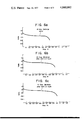
- FIGS. 6 (a-c) are graphical presentations which indicate the cell performance of a nickel cadmium Sub C cell using the tab connections of the present invention.
- the battery assembly 10 of the present invention comprising; a battery housing 12 of generally cylindrical construction, a coiled electrode structure 14, a compatible electrolyte (not shown) and a cover plate 16.
- the coiled electrode structure 14 is formed from elongated strips of electrode material wound in combination with a separator into a conventional jelly-roll configuration.
- the electrolyte may be introduced into the housing 12 either before or after insertion of the assembled coiled electrode structure 14.
- An insulating washer 18 is placed at the bottom end 20 of the housing 12 to insulate the housing bottom from the coiled electrode structure 14.
- the cover plate 16 seals the assembly 10 and is insulated from the housing 12 by a gasket 21.
- the battery housing 12 is electrically connected to one electrode strip of the coiled electrode structure 14 to serve as one battery terminal whereas the cover plate 16 is electrically connected to the other electrode strip of the electrode structure 14 to serve as the opposite battery terminal.
- the coiled electrode structure 14 includes a positive electrode strip 22 and a negative electrode strip 24 separated from one another by a porous separator 26.
- the porous separator 26 can be of any conventional separator material suitable for alkaline cell systems such as, for example, non-woven nylon fibers.
- the separator 26 can be a single sheet interposed between the strips of electrode material 22 and 24 respectively, or can be two or more separating sheets or preferably, and as is shown more clearly in FIG. 2, two sheets stitched, thermally bonded or tacked together along the opposite longitudinal boundaries, to form a sheath with the strips of electrode material 22 and 24 spaced apart and contained therein.
- At least one terminal lead or tab is used to electrically couple each strip of electrode material to its corresponding battery terminal.
- the terminal leads are relatively short conducting tab elements in the form of thin strips of any suitable configuration, preferably rectangular, and selected from a material which will be compatible with the particular electrochemical system of the battery assembly, e.g., in a nickel cadmium cell the tabs should be nickel.
- the conducting tab element 28 is connected to the positive strip of electrode material 22 whereas the conducting tab element 30 is connected to the negative strip of electrode material 24.
- the conducting tab elements 28 or 30, preferably element 30, or both elements includes a multiplicity of projections 32, as is more clearly illustrated in FIGS. 3 and 4, for establishing simultaneous mechanical and electrical engagement to the strip of electrode material to which it is applied.
- the other conducting tab 28 may be connected in a conventional manner to its corresponding strip of electrode material 22.
- the geometry, curvature and height of the projections 32 and the method of their formation are not critical to the present invention. However, for any given type of strip electrode, one particular kind of projection may be favored over another. Moreover, where the tab element is to be connected to the strip of electrode material through the intervening separator this may also favor one kind of projection over another.
- the strip of electrode material is the negative electrode in a nickel-cadmium cell and is fabricated using the pressed powder technique described in U.S. Pat. Nos. 3,310,437 and 3,432,351 respectively, it is preferred to use a multiplicity of projections 32 representing the jagged burrs resulting from corresponding perforations 34 formed in the tab element 30.
- the perforations 34 can be made using any suitable conventional tool, punch press, etc., and need only be confined to a predetermined surface section of the tab element to be placed in abutting relationship with the strip of electrode material 24 or against the covering separator 26. Relatively minor pressure is necessary to firmly establish the connection between the tab and the strip of electrode material. This pressure can be directly and immediately applied upon appropriate placement of the projections against the strip or subsequently applied by compression when the rolled electrode structure 14 is inserted, under pressure, into the battery housing 12.
- Other forms of projections 32 would be metal bristles, teeth, pointed protrusions, etc., extending from one of the tab surfaces.
- the number of projections 32 and their proximity to one another are not critical although as indicated heretofore there may be a preferred arrangement depending upon the strip electrode manufacturing technique.
- the negative electrode be made using the pressed powder technique in which the active electrode material is compacted against a metal current carrying grid which is of open mesh construction.
- the perforated tab projections 32 are preferred and should be of a sufficient number to permit multiple contact with the metal grid in order to assure an electrical conductivity comparable to a welded joint.
- an adhesive covering 36 of insulating material may be placed over the section of the tab element 30 in which the perforations 34 were made to secure the tab until the electrode is coiled.
- Covering 36 need only be a piece of self-adhesive plastic film, or a film over a layer of adhesive.
- the size of the insulated covering 36 should be sufficient to cover the area of the tab 30 containing the perforations with enough overlap to give adhesion to the electrode or separator surface. Covering 36 may be omitted if adhesive is applied between the tab and the electrode or separator surface, or if the projections are pressed firmly into the electrode strip.
- the tab elements 28 and 30 are connected to the cover plate 16 and housing 12 of the battery assembly 10 in a conventional manner with the tab element 28 secured to the cover plate 16 and the tab element 30 bent back upon the assembled coiled electrode structure 14 for making a pressure contact with the battery housing 12.
- the tab element 30 has a double set of projections 32, 32 provided at each opposite end thereof, with one set of projections 32 intended for engaging the electrode strip as explained heretofore and with the opposite set of projections intended to engage the outer wrap of the same electrode strip upon bending the tab 30 under the electrode assembly 14 as shown in FIG. 1 with the smooth back side of the perforated area pressed against the battery housing.
- This alternative design will be effective only in limited cases where the electrode strip is on the outer wrap of the jelly-roll coiled electrode structure 14 and where the battery cell container 12 provides an accessible uninsulated region adjacent to the tab.
- the voltage maintenance during discharge of a cell using a tab element 30 will approximate that of the welded tab connection at 10 and 20 ampere discharges respectively.
- FIG. 6(a-c) indicates the performance of the foregoing NiCd cell at 10 amperes discharge showing a flat voltage response throughout the cycle life of the cell. Although, the equivalent performance curves using welded tabs are not shown they would essentially overlap the curves of FIG. 6.
- tab element Although only one tab element has been shown and described for each strip electrode, it is obvious that multiple tabs can be incorporated and arranged in tandem along the length of the electrode strip to reduce voltage drop normally resulting from longitudinal current flow through the strip.
- Conductive metal tabs with projections may be employed essentially as described to make low resistance mechanical and electrical contacts to electrode strips or plates.
- the electrodes may be of the pressed powder or pasted type on a conductive grid or screen, or may be of the impregnated porous metal sinter type.
- the tab may be applied to the bare electrode surface or may be applied after the separator so the projections penetrate the separator and the electrode beneath.
- the projections are of sufficient depth and number as to insure that a substantial number will contact portions of the grid, screen or sinter as well as the active electrode material.
Landscapes
- Chemical & Material Sciences (AREA)
- Chemical Kinetics & Catalysis (AREA)
- Electrochemistry (AREA)
- General Chemical & Material Sciences (AREA)
- Engineering & Computer Science (AREA)
- Manufacturing & Machinery (AREA)
- Connection Of Batteries Or Terminals (AREA)
- Secondary Cells (AREA)
Priority Applications (6)
| Application Number | Priority Date | Filing Date | Title |
|---|---|---|---|
| US05/657,204 US4049882A (en) | 1976-02-11 | 1976-02-11 | Battery assembly |
| CA269,652A CA1070382A (en) | 1976-02-11 | 1977-01-13 | Spirally-wound battery with improved mechanical connections to electrodes |
| DE2705050A DE2705050C3 (de) | 1976-02-11 | 1977-02-08 | Galvanische Zelle |
| GB5462/77A GB1568544A (en) | 1976-02-11 | 1977-02-10 | Battery assembly |
| JP1403677A JPS52118530A (en) | 1976-02-11 | 1977-02-10 | Battery assembly |
| FR7703805A FR2341208A1 (fr) | 1976-02-11 | 1977-02-10 | Pile electrique a electrodes enroulees |
Applications Claiming Priority (1)
| Application Number | Priority Date | Filing Date | Title |
|---|---|---|---|
| US05/657,204 US4049882A (en) | 1976-02-11 | 1976-02-11 | Battery assembly |
Publications (1)
| Publication Number | Publication Date |
|---|---|
| US4049882A true US4049882A (en) | 1977-09-20 |
Family
ID=24636243
Family Applications (1)
| Application Number | Title | Priority Date | Filing Date |
|---|---|---|---|
| US05/657,204 Expired - Lifetime US4049882A (en) | 1976-02-11 | 1976-02-11 | Battery assembly |
Country Status (6)
| Country | Link |
|---|---|
| US (1) | US4049882A (enExample) |
| JP (1) | JPS52118530A (enExample) |
| CA (1) | CA1070382A (enExample) |
| DE (1) | DE2705050C3 (enExample) |
| FR (1) | FR2341208A1 (enExample) |
| GB (1) | GB1568544A (enExample) |
Cited By (23)
| Publication number | Priority date | Publication date | Assignee | Title |
|---|---|---|---|---|
| US4226920A (en) * | 1978-10-20 | 1980-10-07 | Her Majesty The Queen In Right Of Canada, As Represented By The Minister Of National Defence | Expanded zinc electrode for dry cells |
| US4622277A (en) * | 1985-09-30 | 1986-11-11 | Duracell Inc. | Electrochemical cells |
| DE3719340A1 (de) * | 1986-06-11 | 1987-12-17 | Duracell Int | Elektrochemische zelle, sowie verfahren zur erzeugung eines elektrischen kontaktes zu einer folienelektrode |
| US5006426A (en) * | 1989-08-23 | 1991-04-09 | Matsushita Electric Industrial Co., Ltd. | Alkaline storage battery |
| US5208120A (en) * | 1990-10-09 | 1993-05-04 | Eveready Battery Company, Inc. | Separator for electrochemical cell and process for assembling it into the cell |
| US5663013A (en) * | 1995-05-31 | 1997-09-02 | Sanyo Electric Co., Ltd. | Battery with a spacer between the electrode group and the cover |
| US6013113A (en) * | 1998-03-06 | 2000-01-11 | Wilson Greatbatch Ltd. | Slotted insulator for unsealed electrode edges in electrochemical cells |
| US6284408B1 (en) * | 1998-06-30 | 2001-09-04 | Sanyo Electric Co., Ltd. | Battery having protective tape on connecting band of electrode |
| US6298530B1 (en) | 1997-08-08 | 2001-10-09 | Duracell Inc. | Reinforced coiled electrode assemblies and methods of producing same |
| US6723950B1 (en) * | 2003-02-12 | 2004-04-20 | Medtronic, Inc. | Method for welding thin tabs in wide slots |
| US6729908B2 (en) * | 2001-07-31 | 2004-05-04 | Delphi Technologies, Inc. | Battery pack having perforated terminal arrangement |
| US20050277018A1 (en) * | 2004-05-25 | 2005-12-15 | Kim Cheon S | Secondary battery |
| US20100086858A1 (en) * | 2004-05-25 | 2010-04-08 | Cheon Soo Kim | Secondary battery |
| USRE41886E1 (en) * | 2002-06-05 | 2010-10-26 | Eveready Battery Company, Inc. | Nonaqueous electrochemical cell with improved energy density |
| CN102104133A (zh) * | 2011-01-28 | 2011-06-22 | 福建南平南孚电池有限公司 | 锂电池的极耳、具有该极耳的负极结构和锂电池 |
| US20130143109A1 (en) * | 2010-08-17 | 2013-06-06 | Lg Chem, Ltd. | Secondary Battery Of Improved Lead Structure |
| US20130266876A1 (en) * | 2010-12-14 | 2013-10-10 | Emefcy Ltd. | Spirally wound microbial fuel cell |
| CN104347841A (zh) * | 2014-11-07 | 2015-02-11 | 宁波超霸能源有限公司 | 一次锂电池的负极极耳及其与锂负极片之间的连接结构 |
| CN107507951A (zh) * | 2016-06-14 | 2017-12-22 | 福特全球技术公司 | 用于电池单元的电互连部 |
| US20230268623A1 (en) * | 2022-02-23 | 2023-08-24 | Shenzhen Greensun Technology Co., Ltd. | Method and device for welding and converging battery cell tabs |
| US20240014512A1 (en) * | 2020-11-18 | 2024-01-11 | Lg Energy Solution, Ltd. | Secondary Battery and Manufacturing Method Thereof |
| US12519174B2 (en) | 2021-05-24 | 2026-01-06 | Lg Energy Solution, Ltd. | Unit cell and battery cell including the same |
| US12531315B2 (en) | 2021-05-24 | 2026-01-20 | Lg Energy Solution, Ltd. | Unit cell and battery cell including the same |
Families Citing this family (5)
| Publication number | Priority date | Publication date | Assignee | Title |
|---|---|---|---|---|
| FR2461766A1 (fr) | 1979-07-16 | 1981-02-06 | Michelin & Cie | Electrodes avec sorties de courant |
| JPS6298159U (enExample) * | 1985-12-10 | 1987-06-23 | ||
| JP2541710Y2 (ja) * | 1990-03-29 | 1997-07-16 | セイコー電子工業株式会社 | 円筒形渦巻き式リチウム電池 |
| US5657522A (en) * | 1996-05-14 | 1997-08-19 | Duracell Inc. | Coiled electrode assemblies and methods of producing same |
| AT511667B1 (de) | 2011-06-30 | 2015-07-15 | Avl List Gmbh | Wiederaufladbare elektrische batterie |
Citations (5)
| Publication number | Priority date | Publication date | Assignee | Title |
|---|---|---|---|---|
| US3023260A (en) * | 1959-11-18 | 1962-02-27 | Myron A Coler | Coiled electrode battery |
| US3245837A (en) * | 1962-04-26 | 1966-04-12 | Sanyo Electric Co | Hermetically sealed storage batteries |
| US3393095A (en) * | 1965-05-12 | 1968-07-16 | Varta Ag | Cylindrical battery cells |
| US3496018A (en) * | 1966-04-08 | 1970-02-17 | Gen Electric | Terminal and current collector for compacted powder electrode cells |
| US3732124A (en) * | 1970-07-01 | 1973-05-08 | Accumulateurs Fixes | Electrochemical cells comprising current collector member embedded into the protruding edges of the electrodes |
Family Cites Families (6)
| Publication number | Priority date | Publication date | Assignee | Title |
|---|---|---|---|---|
| US1862297A (en) * | 1929-03-15 | 1932-06-07 | Gen Electric | Capacitor and method forming the same |
| US2615946A (en) * | 1948-07-16 | 1952-10-28 | Katzman Jacob | Flat terminal element for condenser foil |
| US2861115A (en) * | 1956-02-20 | 1958-11-18 | Nickel Cadmium Battery Corp | Battery plate and tab assembly |
| US3080445A (en) * | 1960-07-14 | 1963-03-05 | Union Carbide Canada Ltd | Flat dry cell and battery |
| FR1355264A (fr) * | 1962-04-26 | 1964-03-13 | Sanyo Electric Co | Batterie d'accumulateurs électriques hermétiquement fermée |
| US3966496A (en) * | 1972-08-07 | 1976-06-29 | Gould Inc. | Electrode assembly for air depolarized cells |
-
1976
- 1976-02-11 US US05/657,204 patent/US4049882A/en not_active Expired - Lifetime
-
1977
- 1977-01-13 CA CA269,652A patent/CA1070382A/en not_active Expired
- 1977-02-08 DE DE2705050A patent/DE2705050C3/de not_active Expired
- 1977-02-10 FR FR7703805A patent/FR2341208A1/fr active Granted
- 1977-02-10 GB GB5462/77A patent/GB1568544A/en not_active Expired
- 1977-02-10 JP JP1403677A patent/JPS52118530A/ja active Pending
Patent Citations (5)
| Publication number | Priority date | Publication date | Assignee | Title |
|---|---|---|---|---|
| US3023260A (en) * | 1959-11-18 | 1962-02-27 | Myron A Coler | Coiled electrode battery |
| US3245837A (en) * | 1962-04-26 | 1966-04-12 | Sanyo Electric Co | Hermetically sealed storage batteries |
| US3393095A (en) * | 1965-05-12 | 1968-07-16 | Varta Ag | Cylindrical battery cells |
| US3496018A (en) * | 1966-04-08 | 1970-02-17 | Gen Electric | Terminal and current collector for compacted powder electrode cells |
| US3732124A (en) * | 1970-07-01 | 1973-05-08 | Accumulateurs Fixes | Electrochemical cells comprising current collector member embedded into the protruding edges of the electrodes |
Cited By (36)
| Publication number | Priority date | Publication date | Assignee | Title |
|---|---|---|---|---|
| US4226920A (en) * | 1978-10-20 | 1980-10-07 | Her Majesty The Queen In Right Of Canada, As Represented By The Minister Of National Defence | Expanded zinc electrode for dry cells |
| US4622277A (en) * | 1985-09-30 | 1986-11-11 | Duracell Inc. | Electrochemical cells |
| DE3719340A1 (de) * | 1986-06-11 | 1987-12-17 | Duracell Int | Elektrochemische zelle, sowie verfahren zur erzeugung eines elektrischen kontaktes zu einer folienelektrode |
| US4729162A (en) * | 1986-06-11 | 1988-03-08 | Duracell Inc. | Electrochemical cell asssembly |
| US5006426A (en) * | 1989-08-23 | 1991-04-09 | Matsushita Electric Industrial Co., Ltd. | Alkaline storage battery |
| US5208120A (en) * | 1990-10-09 | 1993-05-04 | Eveready Battery Company, Inc. | Separator for electrochemical cell and process for assembling it into the cell |
| US5663013A (en) * | 1995-05-31 | 1997-09-02 | Sanyo Electric Co., Ltd. | Battery with a spacer between the electrode group and the cover |
| US6298530B1 (en) | 1997-08-08 | 2001-10-09 | Duracell Inc. | Reinforced coiled electrode assemblies and methods of producing same |
| US6013113A (en) * | 1998-03-06 | 2000-01-11 | Wilson Greatbatch Ltd. | Slotted insulator for unsealed electrode edges in electrochemical cells |
| US6284408B1 (en) * | 1998-06-30 | 2001-09-04 | Sanyo Electric Co., Ltd. | Battery having protective tape on connecting band of electrode |
| US6729908B2 (en) * | 2001-07-31 | 2004-05-04 | Delphi Technologies, Inc. | Battery pack having perforated terminal arrangement |
| USRE41886E1 (en) * | 2002-06-05 | 2010-10-26 | Eveready Battery Company, Inc. | Nonaqueous electrochemical cell with improved energy density |
| US6723950B1 (en) * | 2003-02-12 | 2004-04-20 | Medtronic, Inc. | Method for welding thin tabs in wide slots |
| US20050277018A1 (en) * | 2004-05-25 | 2005-12-15 | Kim Cheon S | Secondary battery |
| US20090246639A1 (en) * | 2004-05-25 | 2009-10-01 | Cheon Soo Kim | Secondary battery |
| US20100086858A1 (en) * | 2004-05-25 | 2010-04-08 | Cheon Soo Kim | Secondary battery |
| US8293410B2 (en) * | 2004-05-25 | 2012-10-23 | Samsung Sdi Co., Ltd. | Secondary battery |
| US9508973B2 (en) | 2004-05-25 | 2016-11-29 | Samsung Sdi Co., Ltd. | Secondary battery |
| US9240617B2 (en) | 2004-05-25 | 2016-01-19 | Samsung Sdi Co., Ltd. | Secondary battery |
| US9520589B2 (en) * | 2010-08-17 | 2016-12-13 | Lg Chem, Ltd. | Secondary battery of improved lead structure |
| US20130143109A1 (en) * | 2010-08-17 | 2013-06-06 | Lg Chem, Ltd. | Secondary Battery Of Improved Lead Structure |
| US9478820B2 (en) * | 2010-12-14 | 2016-10-25 | Emefcy Limited | Spirally wound microbial fuel cell |
| US20130266876A1 (en) * | 2010-12-14 | 2013-10-10 | Emefcy Ltd. | Spirally wound microbial fuel cell |
| CN102104133B (zh) * | 2011-01-28 | 2013-03-27 | 福建南平南孚电池有限公司 | 锂电池的极耳、具有该极耳的负极结构和锂电池 |
| CN102104133A (zh) * | 2011-01-28 | 2011-06-22 | 福建南平南孚电池有限公司 | 锂电池的极耳、具有该极耳的负极结构和锂电池 |
| CN104347841B (zh) * | 2014-11-07 | 2016-09-14 | 宁波超霸能源有限公司 | 一次锂电池的负极极耳及其与锂负极片之间的连接结构 |
| CN104347841A (zh) * | 2014-11-07 | 2015-02-11 | 宁波超霸能源有限公司 | 一次锂电池的负极极耳及其与锂负极片之间的连接结构 |
| CN107507951A (zh) * | 2016-06-14 | 2017-12-22 | 福特全球技术公司 | 用于电池单元的电互连部 |
| US10347896B2 (en) * | 2016-06-14 | 2019-07-09 | Ford Global Technologies, Llc | Electrical interconnects for battery cells |
| US10964930B2 (en) | 2016-06-14 | 2021-03-30 | Ford Global Technologies, Llc | Electrical interconnects for battery cells |
| CN107507951B (zh) * | 2016-06-14 | 2022-06-14 | 福特全球技术公司 | 用于电池单元的电互连部 |
| US20240014512A1 (en) * | 2020-11-18 | 2024-01-11 | Lg Energy Solution, Ltd. | Secondary Battery and Manufacturing Method Thereof |
| US12519174B2 (en) | 2021-05-24 | 2026-01-06 | Lg Energy Solution, Ltd. | Unit cell and battery cell including the same |
| US12531315B2 (en) | 2021-05-24 | 2026-01-20 | Lg Energy Solution, Ltd. | Unit cell and battery cell including the same |
| US20230268623A1 (en) * | 2022-02-23 | 2023-08-24 | Shenzhen Greensun Technology Co., Ltd. | Method and device for welding and converging battery cell tabs |
| US11870101B2 (en) * | 2022-02-23 | 2024-01-09 | Shenzhen Greensun Technology Co., Ltd. | Method and device for welding and converging battery cell tabs |
Also Published As
| Publication number | Publication date |
|---|---|
| FR2341208A1 (fr) | 1977-09-09 |
| DE2705050C3 (de) | 1980-07-10 |
| CA1070382A (en) | 1980-01-22 |
| DE2705050B2 (de) | 1979-10-31 |
| DE2705050A1 (de) | 1977-08-18 |
| FR2341208B1 (enExample) | 1981-09-04 |
| GB1568544A (en) | 1980-05-29 |
| JPS52118530A (en) | 1977-10-05 |
Similar Documents
| Publication | Publication Date | Title |
|---|---|---|
| US4049882A (en) | Battery assembly | |
| US4663247A (en) | Coiled electrode assembly cell construction with pressure contact member | |
| US6893772B2 (en) | Current collector for lithium electrode | |
| EP0454419B1 (en) | Connection strips for coiled electrode assemblies | |
| CA1165384A (en) | Contact arrangement for a galvanic battery | |
| US4091186A (en) | Dry cell battery having electrical spring contact adhered to terminal | |
| US4189533A (en) | Stippled substrate for pressed battery plates | |
| CN1998101A (zh) | 低阻抗分层电池设备及其制造方法 | |
| US4105832A (en) | An electro-chemical battery comprising a plate having stippled substrate | |
| US6713211B2 (en) | Square shaped battery | |
| US3960603A (en) | Alkaline battery | |
| WO1995025354A1 (en) | Standard uniform electrode and method of configuring | |
| JP2000077078A (ja) | 渦巻電極を備えた電池及びその製造法 | |
| US4729162A (en) | Electrochemical cell asssembly | |
| US3900340A (en) | Galvanic cell structures employing coiled electrodes | |
| US4317869A (en) | Battery structure | |
| JPH07226197A (ja) | 電 池 | |
| JPH1154135A (ja) | 有機電解液電池 | |
| KR100502315B1 (ko) | 전지의 전극조립체 | |
| JP3262421B2 (ja) | 角形電池用極板の製造方法 | |
| JPS6026452Y2 (ja) | 円筒形アルカリ蓄電池 | |
| JPS60172177A (ja) | アルカリ蓄電池 | |
| CA1194101A (en) | Battery with improved terminal structure and method of manufacture | |
| JP2567647B2 (ja) | 角型密閉電池 | |
| JPH11250928A (ja) | ニッケル・水素二次電池 |
Legal Events
| Date | Code | Title | Description |
|---|---|---|---|
| AS | Assignment |
Owner name: MORGAN GUARANTY TRUST COMPANY OF NEW YORK, AND MOR Free format text: MORTGAGE;ASSIGNORS:UNION CARBIDE CORPORATION, A CORP.,;STP CORPORATION, A CORP. OF DE.,;UNION CARBIDE AGRICULTURAL PRODUCTS CO., INC., A CORP. OF PA.,;AND OTHERS;REEL/FRAME:004547/0001 Effective date: 19860106 |
|
| AS | Assignment |
Owner name: EVEREADY BATTERY COMPANY, INC., CHECKERBOARD SQUAR Free format text: ASSIGNMENT OF ASSIGNORS INTEREST.;ASSIGNOR:UNION CARBIDE CORPORATION, A CORP. OF NY;REEL/FRAME:004660/0534 Effective date: 19860630 Owner name: EVEREADY BATTERY COMPANY, INC., A CORP. OF DE., MI Free format text: ASSIGNMENT OF ASSIGNORS INTEREST;ASSIGNOR:UNION CARBIDE CORPORATION, A CORP. OF NY;REEL/FRAME:004660/0534 Effective date: 19860630 |
|
| AS | Assignment |
Owner name: UNION CARBIDE CORPORATION, Free format text: RELEASED BY SECURED PARTY;ASSIGNOR:MORGAN BANK (DELAWARE) AS COLLATERAL AGENT;REEL/FRAME:004665/0131 Effective date: 19860925 |