US3987237A - Electric furnace wall construction - Google Patents
Electric furnace wall construction Download PDFInfo
- Publication number
- US3987237A US3987237A US05/626,787 US62678775A US3987237A US 3987237 A US3987237 A US 3987237A US 62678775 A US62678775 A US 62678775A US 3987237 A US3987237 A US 3987237A
- Authority
- US
- United States
- Prior art keywords
- hangers
- wall
- insulating
- studs
- apertures
- Prior art date
- Legal status (The legal status is an assumption and is not a legal conclusion. Google has not performed a legal analysis and makes no representation as to the accuracy of the status listed.)
- Expired - Lifetime
Links
Images

Classifications
-
- H—ELECTRICITY
- H05—ELECTRIC TECHNIQUES NOT OTHERWISE PROVIDED FOR
- H05B—ELECTRIC HEATING; ELECTRIC LIGHT SOURCES NOT OTHERWISE PROVIDED FOR; CIRCUIT ARRANGEMENTS FOR ELECTRIC LIGHT SOURCES, IN GENERAL
- H05B3/00—Ohmic-resistance heating
- H05B3/62—Heating elements specially adapted for furnaces
- H05B3/66—Supports or mountings for heaters on or in the wall or roof
Definitions
- the invention relates to a wall structure for an electric furnace.
- Electric ovens particularly those used for annealing, comprise large cavities or compartments having hangers disposed on the inside thereof and usually have a serpentine arrangement of electric resistance heater strips supported by the hangers.
- the walls of such furnaces are typically formed from an outer structural layer, oftentimes formed from sheet steel, and a heat insulating inner layer to which the hangers are secured. It has been the practice to form this inner layer from firebrick or other dense refractory materials. These dense refractory materials conduct substantial amounts of heat from the interior of the furnace to the outer shell thereby allowing the shell to heat to excessive temperatures. Allowing such heat to reach the outer shell lowers the overall efficiency of the furnace to unacceptable levels.
- the electric furnace wall construction of the present invention prevents excessive amounts of heat from being transferred from the interior of the furnace to the outer shell.
- prior art electric furnaces require excessive amounts of time to reach operating temperature and to cool down therefrom which also lowers the overall efficiency of the furnace and therefore increases the costs of any manufacturing process in which heating in such a furnace is a required step.
- the electric furnace wall construction of the present invention does not retain such substantial amounts of heat and therefore lessens the amount of time required to heat to operating temperatures the interior of a furnace in which it is employed.
- the time period required for cooling an electric furnace employing the wall construction of the present invention is also lessened. Therefore, an electric furnace employing the wall construction of the present invention is more efficient to operate than prior art electric furnaces and therefore makes manufacturing processes in which such a furnace is employed less costly.
- the high densities of the firebrick and refractory materials employed in prior art furnaces make the furnace doors extremely heavy and therefore cumbersome to operate.
- the electric furnace wall construction of the present invention is light in weight compared to such prior art furnace walls making the doors employing the construction of the present invention relatively light in weight and easy to operate.
- an object of the present invention to provide an electric furnace wall construction having heat insulative properties which present an outer shell of an electric furnace which employs such a construction from reaching excessive temperatures when the furnace is operating.
- an electric furnace wall comprising a plurality of layers of insulating mineral fiberboard or the like for structural and heat insulative purposes.
- a first or outer layer of insulating mineral fiberboard lines the interior of an outer electric furnace shell.
- An intermediate or second layer of insulating mineral fiberboard overlies the outer layer and is provided with apertures which accept the outer ends of hangers employed to support a serpentine arrangement of electric resistance strip heaters.
- the midportions of the hangers are of lesser cross section than the outer portions of the hangers and are received within mating apertures in an inner or third layer of insulating fiberboard which overlies the intermediate layer.
- the hangerreceiving apertures in the innermost layer being smaller than the apertures in the intermediate layer limit horizontal or inward movement of the hangers.
- the fiberboard layers have the required strength to support the hangers and the electric strip resistance heaters.
- the assembly of the layers of insulating fiberboard is attached to the outer shell by studs and mating locking washers.
- FIG. 1 is a perspective view of an electric furnace employing one form of prior art wall construction.
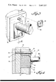
- FIG. 2 is an exploded view of one embodiment of the electric furnace wall construction of the present invention.
- FIG. 3 is a perspective view of the electric furnace wall construction of the present invention partially disassembled to show the details of a fastening means employed therewith.
- FIG. 4 is a sectional view taken along line 4--4 of FIG. 3 in a completely assembled configuration.
- FIG. 1 shows an electric furnace 1 employing one form of prior art wall construction.
- Furnace 1 comprises a plurality of side walls, one of which is shown at 4, a ceiling (not shown), a floor 6 and a door 9 providing access to the furnace interior.
- the walls and door of a prior art electric furnace such as the one shown herein are constructed from a layer of sheet steel 12 lined with dense refractory material such as firebrick 15.
- Supported within the furnace walls, are hangers 17 which themselves support serpentine arrangements of electric resistance heater strips 19 which are provided to heat the furnace to its operating temperature.
- FIGS. 2, 3 and 4 shows an electric furnace wall construction employing a plurality of layers of mineral fiberboard overlying an outer shell.
- the electric furnace wall construction of the present invention comprises an outer shell 25 formed from sheet steel or other material of similar structural rigidity covered on an inner surface thereof by a set 30 of insulating mineral fiberboards of heat insulating material such as, for example, Babcock and Wilcox KAOWOOL comprised of fibers of alumina-silica fireclay.
- mineral insulating fiberboard set 30 comprises an outer solid panel 35 of heat insulating mineral fiberboard 35 and an intermediate apertured panel of heat insulating mineral fiberboard 40 overlying the inner face thereof.
- Each of the apertures of board 40 is sized to mate with a large dimension outer end 45 of a ceramic high-temperature-resistant hanger 50 provided to support, with a multiplicity of similar hangers, a serpentine, or other, arrangement of electric resistance heater strips 19 for the heating of a furnace employing the wall construction of the present invention.
- KAOWOOL is an agglomerate of kaolin fibers having lengths up to 10 inches which are interlaced to form a strong resilient blanket or sheet having excellent insulating properties without the use of added binders.
- Sheets and blocks of this insulating material have a density range of from 14 to 18 pounds per ft. 3 , a working temperature for continuous use of 2300° F, a melting point of greater than 3100° F, a modulus of rupture of 55 PSI, a compressive strength indicated by 5 percent distortion at 3500 lbs./ft. 2 and a linear shrinkage of from 0 at 1800° F to 2 percent at 2400° F.
- the thermal conductivity of this material varies from 0.39 to 1.01 BTU/ft. 2 /in./hr./° F at temperatures ranging from 400° F to 1600° F. Its composition is approximately as follows: SiO 2 -- 52%; Al 2 O 3 --42%; TiO 2 --2%; Fe 2 O 3 --1%; MgO--0.3%; Na 2 O--0.006%, all by weight.
- the electric furnace wall construction of the present invention may be formed from far fewer individual structural components than a prior art electric furnace wall construction formed from individual firebricks. Moreover, since the insulating fiberboards of the present invention are much less dense than the firebrick and other refractory materials employed in prior art electric furnace wall constructions, a wall constructed in accordance with the present invention is much lighter in weight than prior art furnace walls.
- the light weight of the fiberboards coupled with the requirements of relatively few individual fiberboard sets needed for lining an electric furnace wall, makes rebuilding and routine maintenance of such a wall such as the replacement of individual hangers much less time-consuming and costly than similar maintenance performed on a prior art electric furnace wall.
- Overlying intermediate apertured mineral fiberboard 40 is an inner insulating mineral fiberboard 55 having a plurality of apertures 60 therein which mate with midportions 65 of hangers 50. These midportions are of lesser cross section than the outer ends 45 of hangers 50. Therefore, as best shown in FIG. 4, inner fiberboard 55 limits the movement of hanger 50 in a horizontal direction preventing that hanger from pulling out of the wall construction of the present invention.
- Hanger 50 will normally be formed from a relatively dense material, and may therefore be capable of conducting some heat along its length. Since outer insulating fiberboard 35 is solid it will effectively insulate shell 25 from most of such heat conducted along hanger 50 preventing shell 25 from heating to excessive temperatures.
- the electric furnace wall construction of the present invention is provided with a plurality of means attached thereto for supporting with minimal heat less the plurality of insulating fiberboards of the invention and may comprise, for example, studs 70 fixed to the inner surface of outer shell 25 at 75 as by welding or similar methods.
- studs 70 has means cooperating with locking washers for locking the respective insulating boards in place and may, for example, include an arcuate groove 73 and a longitudinal groove 76 disposed between arcuate groove 73 and the inner end of the stud.
- Each of the locking washers 80 includes means for cooperating with the mounting studs to become locked thereupon and may for example be a locking tab 83.
- Each washer 80 is locked to a mating stud 70 by sliding the washer over the stud with the tab in engagement with groove 76 until the tab meets arcuate groove 73. The locking washer is then turned so that tab 83 moves within arcuate groove 73, locking the washer to the stud. Studs 70 cooperate with mating locking washers 80 which, with outer shell 25, press the insulating fiberboards employed in the present invention into an assembled relationship. While a preferred set of cooperating means on the studs and the locking washers for locking the same together has been shown, it is obvious that other locking means may be used. Locking washers 80 in combination with studs 70 provide a time-saving means for assembling and disassembling the electric furnace wall construction of the present invention for the routine maintenance thereof.
- fiberboard 55 or its replacement may then be slid back on studs 70 and locking washers 80 replaced on studs 70 to hold the components of the now rebuilt electric furnace wall in an assembled relationship.
- the respective outer, intermediate and inner fiberboards are lapped and staggered so that seams or joints in adjacent layers do not coincide, providing a heat leakage path.
- the electric furnace wall construction of the present invention being relatively light in weight and comprising relatively few components is capable of being rebuilt or maintained in relatively short periods of time.
- the light weight of the electric furnace wall construction of the present invention also ensures that any furnace door to which it is applied will be light in weight and therefore easy to operate. Since the insulating fiberboards employed in the present invention do not conduct substantial quantities of heat, the outer shells of furnaces employing this construction will remain relatively cool, making such furnaces acceptably efficient. The efficiency of electric furnaces employing the present invention will also be enhanced since the insulating fiberboards will not store substantial quantities of heat, thus reducing the times required to heat and cool the furnace.
- insulating fiberboards 35, 40 and 55 of the furnace wall insulating system of the present invention may be required, depending upon the heat within the oven or furnace and upon the exact material from which the fiberboards are fabricated we find that utilizing the aforementioned kaolin based insulating boards commercially available from Babcock and Wilcox under the commercially available material referred to as KAOWOOL, and insulating against a temperature of 2300° F, it has been found sufficient to use an outer fiberboard 35 approximately 2 inches thick, an intermediate apertured fiberboard 40 approximately 3 inches thick, and finally an inner, hanger-retaining apertured fiberboard approximately 1/2 inch thick.
- the insulation system of the present invention is not limited to the exact arrangement as illustrated.
- the main insulation provided by the 3 inch thick central apertured fiberboard may be alternatively provided by a well-known soft blanket of loosely packed KAOWOOL or equivalent light mineral or ceramic fiber insulation and an added 1/2 inch, for example, apertured fiberboard may be provided immediately inboard of fiberboard 35 to anchor the outer portion of hangers 50.
- other known fiberboards and high-temperature insulation materials may be used rather than the KAOWOOL described in the specific embodiment herein.
- a layer of the same material may be inserted in addition thereto.
- a layer of loosely packed KAOWOOL of moderate thickness such as for example approximately 0.5 inch, added between members 35 and 40.
- Such a layer is of great value in minimizing heat loss through hangers 50.
- Such a member is installed from a continuous roll and helps to seal seams against heat loss.
Landscapes
- Furnace Housings, Linings, Walls, And Ceilings (AREA)
- Vertical, Hearth, Or Arc Furnaces (AREA)
Priority Applications (4)
| Application Number | Priority Date | Filing Date | Title |
|---|---|---|---|
| US05/626,787 US3987237A (en) | 1975-10-29 | 1975-10-29 | Electric furnace wall construction |
| JP51127891A JPS5266807A (en) | 1975-10-29 | 1976-10-26 | Electric furnace wall structure |
| GB44630/76A GB1552848A (en) | 1975-10-29 | 1976-10-27 | Electric furnace wall construction |
| DE2648542A DE2648542C2 (de) | 1975-10-29 | 1976-10-27 | Wand für einen elektrischen Industrieofen |
Applications Claiming Priority (1)
| Application Number | Priority Date | Filing Date | Title |
|---|---|---|---|
| US05/626,787 US3987237A (en) | 1975-10-29 | 1975-10-29 | Electric furnace wall construction |
Publications (1)
| Publication Number | Publication Date |
|---|---|
| US3987237A true US3987237A (en) | 1976-10-19 |
Family
ID=24511852
Family Applications (1)
| Application Number | Title | Priority Date | Filing Date |
|---|---|---|---|
| US05/626,787 Expired - Lifetime US3987237A (en) | 1975-10-29 | 1975-10-29 | Electric furnace wall construction |
Country Status (4)
| Country | Link |
|---|---|
| US (1) | US3987237A (de) |
| JP (1) | JPS5266807A (de) |
| DE (1) | DE2648542C2 (de) |
| GB (1) | GB1552848A (de) |
Cited By (8)
| Publication number | Priority date | Publication date | Assignee | Title |
|---|---|---|---|---|
| FR2453377A1 (fr) * | 1979-04-04 | 1980-10-31 | Dupeux Ets M | Four electrique destine a la cuisson d'articles ceramiques |
| US4272638A (en) * | 1979-03-16 | 1981-06-09 | Johns-Manville Corporation | Heater element supports for use with fibrous block insulations |
| US4346252A (en) * | 1980-09-29 | 1982-08-24 | Wellman Thermal Systems Corporation | Soft wall hanger for furnace |
| EP0072081A1 (de) * | 1981-08-03 | 1983-02-16 | McKECHNIE REFRACTORY FIBRES LIMITED | Modul zur Wärmeisolierung für einen elektrischen Ofen und seine Herstellung |
| US4392052A (en) * | 1981-04-03 | 1983-07-05 | Bulten-Kanthal Ab | Device for carrying electrical resistance elements |
| US4418415A (en) * | 1982-03-08 | 1983-11-29 | Kennecott Corporation | Ceramic fiber insulated furnaces with electrical hanger element of great mechanical integrity |
| US4595826A (en) * | 1982-04-14 | 1986-06-17 | Duran Reginald F | Heat treatment furnace and method of construction |
| US4667396A (en) * | 1984-10-05 | 1987-05-26 | Duran Reginald F | Method of construction of a heat treatment furnace |
Families Citing this family (2)
| Publication number | Priority date | Publication date | Assignee | Title |
|---|---|---|---|---|
| JPS5411336U (de) * | 1977-06-28 | 1979-01-25 | ||
| DE29613515U1 (de) * | 1996-08-03 | 1997-12-04 | GfT Gesellschaft für Feuerfest-Technik mbH, 47441 Moers | Anordnung zur Verminderung der Gaserosion und -korrosion von Feuerfest-Systemen |
Citations (3)
| Publication number | Priority date | Publication date | Assignee | Title |
|---|---|---|---|---|
| US1768865A (en) * | 1928-05-22 | 1930-07-01 | Hevi Duty Electric Co | Heating-element-mounting construction |
| US2591723A (en) * | 1946-01-28 | 1952-04-08 | Foster Wheeler Corp | Lined furnace wall |
| US3368802A (en) * | 1965-06-11 | 1968-02-13 | Alco Standard Corp | Construction of insulated furnace wall |
Family Cites Families (3)
| Publication number | Priority date | Publication date | Assignee | Title |
|---|---|---|---|---|
| US1565575A (en) * | 1923-12-24 | 1925-12-15 | Samuel S Levy | Machine for molding concrete blocks |
| FR1091227A (fr) * | 1954-01-08 | 1955-04-08 | Perfectionnement à la construction des parois de fours électriques | |
| US3705253A (en) * | 1971-09-02 | 1972-12-05 | Wilson Eng Co Inc Lee | Furnace wall construction |
-
1975
- 1975-10-29 US US05/626,787 patent/US3987237A/en not_active Expired - Lifetime
-
1976
- 1976-10-26 JP JP51127891A patent/JPS5266807A/ja active Granted
- 1976-10-27 DE DE2648542A patent/DE2648542C2/de not_active Expired
- 1976-10-27 GB GB44630/76A patent/GB1552848A/en not_active Expired
Patent Citations (3)
| Publication number | Priority date | Publication date | Assignee | Title |
|---|---|---|---|---|
| US1768865A (en) * | 1928-05-22 | 1930-07-01 | Hevi Duty Electric Co | Heating-element-mounting construction |
| US2591723A (en) * | 1946-01-28 | 1952-04-08 | Foster Wheeler Corp | Lined furnace wall |
| US3368802A (en) * | 1965-06-11 | 1968-02-13 | Alco Standard Corp | Construction of insulated furnace wall |
Cited By (8)
| Publication number | Priority date | Publication date | Assignee | Title |
|---|---|---|---|---|
| US4272638A (en) * | 1979-03-16 | 1981-06-09 | Johns-Manville Corporation | Heater element supports for use with fibrous block insulations |
| FR2453377A1 (fr) * | 1979-04-04 | 1980-10-31 | Dupeux Ets M | Four electrique destine a la cuisson d'articles ceramiques |
| US4346252A (en) * | 1980-09-29 | 1982-08-24 | Wellman Thermal Systems Corporation | Soft wall hanger for furnace |
| US4392052A (en) * | 1981-04-03 | 1983-07-05 | Bulten-Kanthal Ab | Device for carrying electrical resistance elements |
| EP0072081A1 (de) * | 1981-08-03 | 1983-02-16 | McKECHNIE REFRACTORY FIBRES LIMITED | Modul zur Wärmeisolierung für einen elektrischen Ofen und seine Herstellung |
| US4418415A (en) * | 1982-03-08 | 1983-11-29 | Kennecott Corporation | Ceramic fiber insulated furnaces with electrical hanger element of great mechanical integrity |
| US4595826A (en) * | 1982-04-14 | 1986-06-17 | Duran Reginald F | Heat treatment furnace and method of construction |
| US4667396A (en) * | 1984-10-05 | 1987-05-26 | Duran Reginald F | Method of construction of a heat treatment furnace |
Also Published As
| Publication number | Publication date |
|---|---|
| JPS5266807A (en) | 1977-06-02 |
| DE2648542A1 (de) | 1977-05-05 |
| GB1552848A (en) | 1979-09-19 |
| DE2648542C2 (de) | 1982-04-01 |
| JPS5531396B2 (de) | 1980-08-18 |
Similar Documents
| Publication | Publication Date | Title |
|---|---|---|
| US4088825A (en) | Electric furnace wall construction | |
| CA1127011A (en) | Apparatus for lining the inner walls of industrial furnaces | |
| US3854262A (en) | Inpaled and compressed fibrous furnace lining | |
| US3987237A (en) | Electric furnace wall construction | |
| AU594814B2 (en) | Furnaces | |
| JPH0121436B2 (de) | ||
| US5775269A (en) | Boiler protection tube assembly | |
| US4698948A (en) | Furnace wall construction for industrial use | |
| US2993845A (en) | Metal plug type coke oven door | |
| EP0029340B1 (de) | Trapezförmige Isolierung aus ineinandergreifenden Teilen und isoliertes Rohr | |
| US3363889A (en) | Industrial furnace and oven wall | |
| JPS584271B2 (ja) | セラミツクヨウソ オヨビ セラミツクヨウソオフクムダンネツクミタテタイ | |
| US4272638A (en) | Heater element supports for use with fibrous block insulations | |
| EP0032319B1 (de) | Ofen mit feuerfester Abdichtung für hervorspringende Rohrenden | |
| JPH0633950B2 (ja) | 炉の天井の支持構造体 | |
| US4802425A (en) | High temperature fiber system with controlled shrinkage and stress resistance | |
| US4900247A (en) | High-temperature heating furnace | |
| EP0258987B1 (de) | Mechanisch verbundene zweilagige Faserstoff-Isolierung | |
| JPS591984A (ja) | 工業炉の炉壁構造 | |
| JPH0719754A (ja) | セラミックファイバーモジュール | |
| US3073264A (en) | Furnace roof suspended by interconnected brick hanger extensions | |
| US925902A (en) | Electric kiln. | |
| EP0053875B1 (de) | Wärmeisolierende Auskleidungsplatte für hohe Temperaturen | |
| US3005422A (en) | Refractory roof | |
| US1612795A (en) | Fire arch for furnaces |