US3912440A - Apparatus to expand a laminating interlayer - Google Patents
Apparatus to expand a laminating interlayer Download PDFInfo
- Publication number
- US3912440A US3912440A US523089A US52308974A US3912440A US 3912440 A US3912440 A US 3912440A US 523089 A US523089 A US 523089A US 52308974 A US52308974 A US 52308974A US 3912440 A US3912440 A US 3912440A
- Authority
- US
- United States
- Prior art keywords
- cooling
- cone
- web
- drum
- stretching
- Prior art date
- Legal status (The legal status is an assumption and is not a legal conclusion. Google has not performed a legal analysis and makes no representation as to the accuracy of the status listed.)
- Expired - Lifetime
Links
- 239000011229 interlayer Substances 0.000 title abstract description 25
- 238000010030 laminating Methods 0.000 title abstract description 13
- 239000000463 material Substances 0.000 claims abstract description 76
- 238000010438 heat treatment Methods 0.000 claims abstract description 22
- 238000001816 cooling Methods 0.000 claims description 86
- 230000000704 physical effect Effects 0.000 claims description 4
- 125000000391 vinyl group Chemical group [H]C([*])=C([H])[H] 0.000 description 25
- 229920002554 vinyl polymer Polymers 0.000 description 25
- 239000011521 glass Substances 0.000 description 8
- 239000012809 cooling fluid Substances 0.000 description 5
- 238000000034 method Methods 0.000 description 5
- 239000012530 fluid Substances 0.000 description 4
- 229920002037 poly(vinyl butyral) polymer Polymers 0.000 description 4
- 230000009471 action Effects 0.000 description 3
- 230000015572 biosynthetic process Effects 0.000 description 3
- 230000008859 change Effects 0.000 description 3
- LYCAIKOWRPUZTN-UHFFFAOYSA-N Ethylene glycol Chemical compound OCCO LYCAIKOWRPUZTN-UHFFFAOYSA-N 0.000 description 2
- 230000005540 biological transmission Effects 0.000 description 2
- 238000003475 lamination Methods 0.000 description 2
- 239000003795 chemical substances by application Substances 0.000 description 1
- 238000010276 construction Methods 0.000 description 1
- 230000008878 coupling Effects 0.000 description 1
- 238000010168 coupling process Methods 0.000 description 1
- 238000005859 coupling reaction Methods 0.000 description 1
- 230000003247 decreasing effect Effects 0.000 description 1
- 230000007547 defect Effects 0.000 description 1
- 230000001419 dependent effect Effects 0.000 description 1
- 239000000428 dust Substances 0.000 description 1
- 230000004438 eyesight Effects 0.000 description 1
- 230000004313 glare Effects 0.000 description 1
- WGCNASOHLSPBMP-UHFFFAOYSA-N hydroxyacetaldehyde Natural products OCC=O WGCNASOHLSPBMP-UHFFFAOYSA-N 0.000 description 1
- 230000006872 improvement Effects 0.000 description 1
- 238000009434 installation Methods 0.000 description 1
- 238000004519 manufacturing process Methods 0.000 description 1
- 229920000642 polymer Polymers 0.000 description 1
- 230000009467 reduction Effects 0.000 description 1
- 239000012487 rinsing solution Substances 0.000 description 1
- XLYOFNOQVPJJNP-UHFFFAOYSA-N water Substances O XLYOFNOQVPJJNP-UHFFFAOYSA-N 0.000 description 1
Images

Classifications
-
- B—PERFORMING OPERATIONS; TRANSPORTING
- B32—LAYERED PRODUCTS
- B32B—LAYERED PRODUCTS, i.e. PRODUCTS BUILT-UP OF STRATA OF FLAT OR NON-FLAT, e.g. CELLULAR OR HONEYCOMB, FORM
- B32B17/00—Layered products essentially comprising sheet glass, or glass, slag, or like fibres
- B32B17/06—Layered products essentially comprising sheet glass, or glass, slag, or like fibres comprising glass as the main or only constituent of a layer, next to another layer of a specific material
- B32B17/10—Layered products essentially comprising sheet glass, or glass, slag, or like fibres comprising glass as the main or only constituent of a layer, next to another layer of a specific material of synthetic resin
- B32B17/10005—Layered products essentially comprising sheet glass, or glass, slag, or like fibres comprising glass as the main or only constituent of a layer, next to another layer of a specific material of synthetic resin laminated safety glass or glazing
- B32B17/1055—Layered products essentially comprising sheet glass, or glass, slag, or like fibres comprising glass as the main or only constituent of a layer, next to another layer of a specific material of synthetic resin laminated safety glass or glazing characterized by the resin layer, i.e. interlayer
- B32B17/10761—Layered products essentially comprising sheet glass, or glass, slag, or like fibres comprising glass as the main or only constituent of a layer, next to another layer of a specific material of synthetic resin laminated safety glass or glazing characterized by the resin layer, i.e. interlayer containing vinyl acetal
-
- B—PERFORMING OPERATIONS; TRANSPORTING
- B29—WORKING OF PLASTICS; WORKING OF SUBSTANCES IN A PLASTIC STATE IN GENERAL
- B29C—SHAPING OR JOINING OF PLASTICS; SHAPING OF MATERIAL IN A PLASTIC STATE, NOT OTHERWISE PROVIDED FOR; AFTER-TREATMENT OF THE SHAPED PRODUCTS, e.g. REPAIRING
- B29C55/00—Shaping by stretching, e.g. drawing through a die; Apparatus therefor
- B29C55/02—Shaping by stretching, e.g. drawing through a die; Apparatus therefor of plates or sheets
- B29C55/04—Shaping by stretching, e.g. drawing through a die; Apparatus therefor of plates or sheets uniaxial, e.g. oblique
- B29C55/045—Shaping by stretching, e.g. drawing through a die; Apparatus therefor of plates or sheets uniaxial, e.g. oblique in a direction which is not parallel or transverse to the direction of feed, e.g. oblique
-
- B—PERFORMING OPERATIONS; TRANSPORTING
- B29—WORKING OF PLASTICS; WORKING OF SUBSTANCES IN A PLASTIC STATE IN GENERAL
- B29C—SHAPING OR JOINING OF PLASTICS; SHAPING OF MATERIAL IN A PLASTIC STATE, NOT OTHERWISE PROVIDED FOR; AFTER-TREATMENT OF THE SHAPED PRODUCTS, e.g. REPAIRING
- B29C67/00—Shaping techniques not covered by groups B29C39/00 - B29C65/00, B29C70/00 or B29C73/00
- B29C67/0011—Shaping techniques not covered by groups B29C39/00 - B29C65/00, B29C70/00 or B29C73/00 for shaping plates or sheets
-
- B—PERFORMING OPERATIONS; TRANSPORTING
- B32—LAYERED PRODUCTS
- B32B—LAYERED PRODUCTS, i.e. PRODUCTS BUILT-UP OF STRATA OF FLAT OR NON-FLAT, e.g. CELLULAR OR HONEYCOMB, FORM
- B32B17/00—Layered products essentially comprising sheet glass, or glass, slag, or like fibres
- B32B17/06—Layered products essentially comprising sheet glass, or glass, slag, or like fibres comprising glass as the main or only constituent of a layer, next to another layer of a specific material
- B32B17/10—Layered products essentially comprising sheet glass, or glass, slag, or like fibres comprising glass as the main or only constituent of a layer, next to another layer of a specific material of synthetic resin
- B32B17/10005—Layered products essentially comprising sheet glass, or glass, slag, or like fibres comprising glass as the main or only constituent of a layer, next to another layer of a specific material of synthetic resin laminated safety glass or glazing
- B32B17/1055—Layered products essentially comprising sheet glass, or glass, slag, or like fibres comprising glass as the main or only constituent of a layer, next to another layer of a specific material of synthetic resin laminated safety glass or glazing characterized by the resin layer, i.e. interlayer
- B32B17/10559—Shape of the cross-section
- B32B17/10568—Shape of the cross-section varying in thickness
-
- B—PERFORMING OPERATIONS; TRANSPORTING
- B32—LAYERED PRODUCTS
- B32B—LAYERED PRODUCTS, i.e. PRODUCTS BUILT-UP OF STRATA OF FLAT OR NON-FLAT, e.g. CELLULAR OR HONEYCOMB, FORM
- B32B17/00—Layered products essentially comprising sheet glass, or glass, slag, or like fibres
- B32B17/06—Layered products essentially comprising sheet glass, or glass, slag, or like fibres comprising glass as the main or only constituent of a layer, next to another layer of a specific material
- B32B17/10—Layered products essentially comprising sheet glass, or glass, slag, or like fibres comprising glass as the main or only constituent of a layer, next to another layer of a specific material of synthetic resin
- B32B17/10005—Layered products essentially comprising sheet glass, or glass, slag, or like fibres comprising glass as the main or only constituent of a layer, next to another layer of a specific material of synthetic resin laminated safety glass or glazing
- B32B17/10807—Making laminated safety glass or glazing; Apparatus therefor
- B32B17/10889—Making laminated safety glass or glazing; Apparatus therefor shaping the sheets, e.g. by using a mould
Definitions
- the apparatus includes structure for stretching a heated web of laminating interlayer material between a cylindrical heating structure and a conical member in such a manner that a constant rectangular plane is defined in the space between the point at which the web leaves the cylindrical structure and the point at which it contacts the conical member.
- the stretching of the web occurs between these two points because the web engaging the larger end of the conical member is stretched to a greater degree than the portion of the web engaging the smaller end of the conical member as the different ends of the conical member are moving at different'surface speeds.
- the web is cooled on the conical member.
- the stretching of such material is desirable when a tinted band is placed along one lateral edge of the material so that the material may be used in the formation of a tinted windshield for an automotive vehicle. More particularly, the tinted or gradient band is located at the top of the windshield in order to reduce the light transmission capability of the windshield in that area. This reduction in light transmission aids the operator of the vehicle by reducing the amount of glare he is subject to, thereby improving his field or vision.
- the gradient band windshield has both horizontal and vertical curvature
- the interlayers for different windshield willl have the lateral edges thereof formed into curved configurations of different arc lengths.
- the material is produced in large rolls with the lateral edges thereof in a parallel and straight condition. Many individual interlayers may be formed from one such large roll of material.
- the patents mentioned above show methods and apparatuses for stretching the original continuous length of interlayer material into a stretched condition to make it acceptable for use in a laminating procedure.
- the apparatus of this invention is an improvement over the apparatuses known in the prior art in that the present apparatus assures that the stretching forces applied to the material are always applied in a uniform and predictable ratio dependent only on the relative material contact points in the stretching apparatus.
- the control allowed by the present apparatus to the stretch gap geometry is superior to any known in the prior art.
- This invention relates to an apparatus for expanding a continuous length of material and, more particularly, to an apparatus for expanding material so that originally parallel and straight lateral edges thereof are stretched to curved configurations of different arc lengths.
- the expanding apparatus includes a heat drum in the form of a cylinder.
- First structure is provided for mounting the heat drum for rotation about its cylindrical axis.
- a heating device supplies heat internally of the heat drum.
- a first motor drives the heat drum so that the drum pulls the material to be expanded from a continuous supply thereof over a substantial portion of its cylindrical surface so that the material may be heated to a temperature whereat it is in an increasingly pliable condition.
- a first cooling cone having a slant height greater than the width of the material is mounted by second structure at a particular'distance from the heat drum.
- the cooling cone is mounted in a position such that a selected slant height position along the cooling cone is in a parallel spaced relationship with respect to a selected tangent position along the cylindrical surface of the heat drum. This locating permits a rectangular plane to be defined in the particular distance between the selected slant height position and the selected tangent position between the head drum and the cooling cone.
- a cooling device is provided for cooling the interior of the cooling cone.
- a second motor drives the cooling cone. Electrical control circuits are provided for controlling the second motor so that the cooling cone supplies a stretching force to the material between the heat drum and the cooling cone. This stretching action causes the portion of the material engaging the larger end of the cooling cone to be stretched to a greater degree than the portion of the material engaging the smaller end of the cooling cone.
- the material to be stretched leaves the heat drum at the selected tangent position, is subjected to stretching stresses and relieving of such stresses during movement across the particular distance, and then is brought into contact with the cooling cone at the selected slant height position.
- the particular distance between the heat drum and the cooling cone is selected to be sufficient to accomplish a stretching of the material without disruption of its physical properties.
- the apparatus of this invention stretches the material by the application of controllable stretching forces, that is by the use of the motor driving the cooling cone.
- the apparatus permits a substantial increase in speed of operation of such a stretching apparatus than heretofore achievable as well as permitting greater uniformity in the product regardless of the amount of stretching because of the ability to provide uniform heating and uniform cooling of the material prior to and after stretching.
- FIG. 1 is a plan view of the apparatus of this invention.
- FIG. 2 is a side elevational view of the apparatus of this invention.
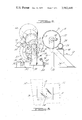
- FIG. 3 is a schematic representation of the material being subject to stretching forces. This Figure shows the rectangular attitude taken by the material during its passage between the heating and cooling portions of the stretching apparatus.
- a pair of glass templets are laminated together with an interposed sheet of plasticized polyvinyl butyral.
- the glass templets have an approximate thickness of 0.100 inch and the interlayer has a thickness of approximately 0.030 inch.
- the formation of such a laminated assembly is well known in the art.
- This particular band is generally known as the gradient band and is preferably graduated with the intensity of coloration decreasing from the top of the windshield to a position spaced from the bottom thereof.
- the vinyl material used for the interlayer is in a continuous roll wherein the opposite lateral edges thereof are in a substantially parallel relationship.
- finite lengths of the interlayer are formed from the roll in such a configuration that the upper and the lower lateral edges of the interlayer are stretched to curved configurations of different arc lengths.
- the upper edge of the gradient band interlayer is of shorter arc length than the lower edge thereof.
- the apparatus for stretching such material will be best understood by reference to the associated drawings wherein the apparatus is generally identified by the numeral 10. With reference to FIGS. 1 and 2 of the drawings, a continuous roll of commercially available, polyvinyl butyral 12 is shown as it is unwound from a coil thereof (not shown).
- the roll of vinyl is formed so that one edge thereof has a gradient tinted band 14 thereon.
- the vinyl material is unrolled and put through a plurality of rinsing solutions at a rinsing station (not shown). At such a rinsing station, water is used to wash from the surface of the vinyl fine dust material which is placed thereon in order to keep the various convolutions of the material in the roll separate during its handling and shipping.
- the web 12 After passing through the rinsing station, the web 12 is passed around a drum 16 which is mounted for rotation on a shaft 18 which is supported by a pair of upstanding members 20.
- the upstanding members are secured to a bass plate 22 and are further supported by a brace member 24.
- a motor 26 is provided which drives a gear 28.
- the motor is mounted on support structure 30 associated with one of the brace members.
- the gear 28 engages a gear 32 secured to the drum.
- the shaft 18 supporting the drum 16 has a hollow interior and only extends a portion of the way into the drum on each side thereof.
- the drum is a completely sealed unit having a hollow interior.
- An inlet pipe 34 and an exhaust pipe 36 are connected at opposite ends of the shaft so that a heating medium may be supplied to the interior of the drum.
- the heating medium heats the vinyl material which is passing over the surface of the drum.
- the left side of the movable platform has a pair of support wheels 40 which are movable over a track 42.
- the right side of the movable platform is supported by guide wheels 44 having a groove 46 therein which locates the wheels on a guide track 48.
- a hydraulic cylinder 50 operates a piston which has a rod 54 associated therewith.
- the rod has a coupling member 56 which connects it to the movable platform.
- the hydraulic cylinder by movement of its piston, is effective to operate the movable platform to position it in different positions with respect to the drum.
- the manner in which the hydraulic cylinder is operated to cause movement of the plantform is described in copending U.S. patent application Ser. No. 489,272, filed Aug. 5, 1974 and entitled Apparatus For Expanding A Laminating interlayer, which application is assigned to the same assignee as this application and is hereby incorporated by reference. I
- a lower cooling cone 58 and an upper cooling cone 60, both truncated, are shown in the drawings as being rotatably mounted by a front standard 62 and a rear standard 64 to the movable platform 38. While two cooling cones are shown in the drawings, any number of cooling cones may be employed with the apparatus 10 of this invention. For example, one or more cooling cones may be employed depending upon the amount of cooling which is necessary to cool the vinyl material which has been stretched.
- the cooling is carried out by allowing cooling fluid to flow into the cone through inlet pipes 59 and be removed therefrom through exhaust pipes 61. Preferentialy the cooling fluid, while in its coolest condition, contacts the smaller end of the cone and proceeds toward the larger end of the cone. The purpose of this preferential type of cooling action will be described hereinbelow.
- a motor 66 has a chain drive 68 associated therewith.
- the chain drive drives the lower cooling cone 58 and a second chain drive 69 driven by a reversing gear on the lower cooling cone, drives the upper cone so that both cones are driven at a desired rotational speed.
- the motor and chain drives are secured to the movable platform 38 for movement therewith.
- a first gauging head 70 and a second guaging head 72 are mounted by posts 74 and 76, respectively to the movable platform 38. These gauging heads may be moved any place along a gauging track 78 so as to accomodate the width of the vinyl passing therethrough. The gauging heads may be adjusted so that they are associated with different positions along the slant height of the cones 58 and 60. The gauging heads are adjusted by loosening the bolts which secure their posts to the gauging track.
- the gauging heads are designed to locate the edge of the web and to keep it in a particular position with respect to a location on the cooling cones which has been selected for stretching the vinyl to a particular configuration having certain desired upper and lower radii of curvature. The exact manner in which the heads function to accomplish this purpose if fully described in the aforementioned patent application.
- FIG. 3 there is graphically illustrated the position the vinyl assumes as it is being stretched between the heating drum l6 and the first cooling cone 58.
- the drum and cooling cone are shown in FIG. 3 on phantom.
- the material leaves the heating drum at a tagent position indicated by line A in FIG. 3 and point A in FIG. 2, moves across a zone in which it maintains a substantially rectangular attitude, and contacts the lower cone 58 at a selected slant height position indicated by the line B in FIG. 3 and point B in FIG. 2.
- the material in the zone maintains a substantially rectangular shape but may neck down slightly at a location close to the heat drum because of the stretching forces applied thereto.
- the larger end of the cone will apply a greater stretching force because the surface speed of the larger end is greater than the surface speed of the smaller end.
- the web 12 of commercially available plasticized polyvinyl-butyral is used as the interlayer material.
- This material is commercially available in lengths of 800 and 1500 feet with various widths, for example of about 30 inches.
- the rate of unwinding and rinsing of the vinyl is 65 feet per minute.
- the slant height of each cone is 75 inches and the edge of the web having the gradient band 14 therealong passes over the cone at a distance of inches from the small end thereof whereby the radius of curvature developed in the end having the gradient band therealong is 80 inches and the other end is l 10 inches.
- the web 12 passes from the rinsing station, not shown, over an idler roller and onto the surface of the drum 16.
- the drum is rotated through the driving motor 26 operating on gears 28 and 32. With this driving action the web is pulled from its continuous supply though the rinsing station and onto the surface of the drum.
- the web is in contact with the drum surface along a substantial length thereof.
- the web is heated to a temperature in the range of about 200F by introducing a heating fluid such as steam under pressure through the inlet pipe 34 into the interior of the drum.
- the heating fluid heats the vinyl to a temperature whereat it is in a more pliable condition.
- the heating medium is exhausted from the interior of the drum through exhaust pipe 36.
- the web reaches its highest temperature at point A, that is the selected tangent position, where it is removed from the surface of the drum. At point A, the vinyl web is pliable enought to be stretched.
- the pliable web 12 is stretched between tangent position A of the drum l6 and the selected slant height position B of the lower cooling cone 58.
- the stretching occurs between these positions because the points along the slant height of the cone into which the web comes into contact are moving at different velocities and thus apply different forces to the material across its width.
- the large end of the cone will be traveling at a greater surface speed and will stretch the web in that vicinity to a greater degree than the web is stretched by the small end of the cone.
- a small amount of necking down of the material takes place and this is generally confined to a location adjacent the tangent position A of the heat drum.
- the stretching force of the lower cooling cone is developed from motor 66 acting through the drive chain 68 to drive the cooling cone.
- the web passes over the cooling cones 58 and 60 its temperature is reduced to about 50F.
- the web is removed from the upper cooling cone and cut into finite lengths
- the web is cooled while in contact with the cooling cones by using a cooling fluid such as glycol which is introduced into the cooling cones through inlet pipes 59.
- the cooling fluid flows through the cones from the small end of the cones to the large end thereof by the use of internal baffels for directing the cooling fluid against the internal surface area of the cones in a known manner.
- the fluid is exhausted through the exhaust pipe 61.
- each cone which contacts less surface area of the web per unit volume thereof has the coldest fluid and thus a better differential for heat transfer whereas the larger end of the cone has a reduced differential for heat transfer but has less of a cooling requirement because the unit volume to be cooled per unit surface area is less.
- the vinyl web is heated, expanded and cooled prior to being cut into finite lengths.
- the apparatus permits more uniform heating and cooling patterns to be applied to vinyl material and permits rapid changes between different stretching regimes without requiring extensive adjustments of those heating and cooling patterns.
- the vinyl is stretched in a stretching regime in which sufficient time is alloted between the heating of the material to a pliable condition and the cooling of the material to set it up to permit a stretching of the material without otherwise changing its physical properties.
- the expansion of the material is accomplished by applying a stretching force to the material which expands the same in a controlled manner not destroying certain polymer cross-links and other physical characteristics thereof such as elasticity and adhesion to glass.
- Vinyl which has been properly stretched does not have any defects therein such as localized thin spots, creases and/or fold marks.
- Vinyl material which has been properly stretched may be tested by laminating a test windshield to see if the material bonds properly and by subsequently fracturing such a windshield to see if the material functions in its normal manner by retaining the portions of glass adhered thereto.
- heating means for supplying heat internally of said head drum
- first motor means for driving said heat drum so that said heat drum pulls said material from a continuous supply thereof and over a substantial portion of its cylindrical surface to heat the same to a temperature whereat it is a pliable condition;
- second structure means for mounting said first cooling cone at a particular distance from said heat drum in a position such that a selected slant height position along said cooling cone is in a parallel spaced position with respect to a selected tangent position along the cylindrical surface of said heat drum whereby a rectangular plane is defined in said particular distance between said selected slant height position and said selected tangent position;
- cooling means for cooling the interior of said cooling cone
- said cooling means is for cooling the interior of said cooling cone from thesmall end thereof to the large end thereof whereby a greater thermal driving force is available for cooling in the area of the cone contacted by the material stretched to the lesser degree.
Landscapes
- Engineering & Computer Science (AREA)
- Mechanical Engineering (AREA)
- Shaping By String And By Release Of Stress In Plastics And The Like (AREA)
- Joining Of Glass To Other Materials (AREA)
- Automobile Manufacture Line, Endless Track Vehicle, Trailer (AREA)
Priority Applications (7)
| Application Number | Priority Date | Filing Date | Title |
|---|---|---|---|
| US523089A US3912440A (en) | 1974-11-12 | 1974-11-12 | Apparatus to expand a laminating interlayer |
| CA235,174A CA1050227A (en) | 1974-11-12 | 1975-09-10 | Apparatus to expand a laminating interlayer |
| IT51353/75A IT1047532B (it) | 1974-11-12 | 1975-09-15 | Apparecchio per espandere un interstrato di laminatura in articolare per la fabbricazione di parabrezza di autoveicoli |
| GB4093775A GB1475949A (en) | 1974-11-12 | 1975-10-07 | Apparatus for stretching a continuous length of material |
| DE2546922A DE2546922C2 (de) | 1974-11-12 | 1975-10-20 | Vorrichtung zum Strecken eines Bahnmaterials aus Kunststoff |
| FR7533756A FR2291012A1 (fr) | 1974-11-12 | 1975-11-05 | Appareil pour etirer une matiere destinee a servir de couche intermediaire pour la fabrication d'une structure feuilletee |
| JP50134217A JPS5170271A (en) | 1974-11-12 | 1975-11-10 | Sekisochukansono kakuchosochi |
Applications Claiming Priority (1)
| Application Number | Priority Date | Filing Date | Title |
|---|---|---|---|
| US523089A US3912440A (en) | 1974-11-12 | 1974-11-12 | Apparatus to expand a laminating interlayer |
Publications (1)
| Publication Number | Publication Date |
|---|---|
| US3912440A true US3912440A (en) | 1975-10-14 |
Family
ID=24083617
Family Applications (1)
| Application Number | Title | Priority Date | Filing Date |
|---|---|---|---|
| US523089A Expired - Lifetime US3912440A (en) | 1974-11-12 | 1974-11-12 | Apparatus to expand a laminating interlayer |
Country Status (7)
| Country | Link |
|---|---|
| US (1) | US3912440A (cg-RX-API-DMAC10.html) |
| JP (1) | JPS5170271A (cg-RX-API-DMAC10.html) |
| CA (1) | CA1050227A (cg-RX-API-DMAC10.html) |
| DE (1) | DE2546922C2 (cg-RX-API-DMAC10.html) |
| FR (1) | FR2291012A1 (cg-RX-API-DMAC10.html) |
| GB (1) | GB1475949A (cg-RX-API-DMAC10.html) |
| IT (1) | IT1047532B (cg-RX-API-DMAC10.html) |
Cited By (16)
| Publication number | Priority date | Publication date | Assignee | Title |
|---|---|---|---|---|
| DE2742897A1 (de) * | 1977-09-23 | 1979-04-05 | Asahi Glass Co Ltd | Verfahren zur herstellung von automobil-windschutzscheiben |
| US4554713A (en) * | 1982-09-07 | 1985-11-26 | Ppg Industries, Inc. | Apparatus for differentially stretching, aligning and cutting sheet material |
| US4768939A (en) * | 1987-11-17 | 1988-09-06 | Monsanto Company | Apparatus for forming shaped interlayer blanks |
| US4808357A (en) * | 1987-11-17 | 1989-02-28 | Monsanto Company | Process for forming shaped interlayer blanks |
| EP0317545A3 (en) * | 1987-11-17 | 1990-04-25 | Monsanto Company | Process for forming plasticized polyvinyl butyral sheet |
| WO1991006031A1 (en) * | 1989-10-16 | 1991-05-02 | Libbey-Owens-Ford Co. | Display panel for a vehicle windshield |
| US5071601A (en) * | 1989-06-30 | 1991-12-10 | Central Glass Company, Limited | Method for stretching web of plastic sheet into arcuate form |
| US5087502A (en) * | 1987-11-17 | 1992-02-11 | Monsanto Company | Process and intermediate sheet for forming shaped interlayer blanks |
| US5100497A (en) * | 1991-01-31 | 1992-03-31 | Steelastic West, Inc. | Method and apparatus for forming an apex filler and/or applying an apex filler to a bead ring sub-assembly |
| US5130174A (en) * | 1989-10-12 | 1992-07-14 | Monsanto Company | Shaped interlayer blank |
| US5203938A (en) * | 1991-01-31 | 1993-04-20 | Heico Aluminum Products, Inc. | Method and apparatus for forming an apex filler and/or applying an apex filler to a bead ring sub-assembly |
| EP0685316A1 (en) * | 1994-06-01 | 1995-12-06 | Monsanto Europe S.A./N.V. | Apparatus and method for forming cut arcuate blanks |
| US5735995A (en) * | 1996-02-13 | 1998-04-07 | The Steelastic Company, L.L.C. | Apparatus for applying an apex filler to a bead ring |
| US6534152B2 (en) * | 1989-09-28 | 2003-03-18 | Ppg Industries Ohio, Inc. | Windshield for head-up display system |
| US20140141193A1 (en) * | 2012-11-20 | 2014-05-22 | Airbus Operations Gmbh | Method and apparatus for forming a curved prepreg strip |
| US10857702B2 (en) * | 2016-12-29 | 2020-12-08 | Saint-Gobain Glass France | Forming method of a PVB film for HUD |
Families Citing this family (3)
| Publication number | Priority date | Publication date | Assignee | Title |
|---|---|---|---|---|
| CA1054323A (en) * | 1975-01-22 | 1979-05-15 | Daniel J. Gurta | Device for stretching laminating interlayers |
| JPS589776B2 (ja) * | 1977-09-07 | 1983-02-22 | 旭硝子株式会社 | ポリビニ−ルブチラ−ル合せガラス中間膜の伸展方法 |
| US4882006A (en) * | 1986-12-23 | 1989-11-21 | Nippon Sheet Glass Co., Ltd. | System for stretching and severing strip-like resin sheet |
Citations (4)
| Publication number | Priority date | Publication date | Assignee | Title |
|---|---|---|---|---|
| US2559648A (en) * | 1948-04-09 | 1951-07-10 | Sweets Lab Inc | Coated candy chewing gum and method of making same |
| US3019475A (en) * | 1960-03-08 | 1962-02-06 | Pittsburgh Plate Glass Co | Stretching apparatus |
| US3696186A (en) * | 1969-11-28 | 1972-10-03 | Fod Motor Co | Method of expanding a pliable material |
| US3762147A (en) * | 1971-07-15 | 1973-10-02 | Rieter Ag Maschf | Apparatus of relaxing drawn high-polymeric filament threads |
Family Cites Families (1)
| Publication number | Priority date | Publication date | Assignee | Title |
|---|---|---|---|---|
| US3885899A (en) * | 1974-08-05 | 1975-05-27 | Ford Motor Co | Apparatus for expanding a laminating interlayer |
-
1974
- 1974-11-12 US US523089A patent/US3912440A/en not_active Expired - Lifetime
-
1975
- 1975-09-10 CA CA235,174A patent/CA1050227A/en not_active Expired
- 1975-09-15 IT IT51353/75A patent/IT1047532B/it active
- 1975-10-07 GB GB4093775A patent/GB1475949A/en not_active Expired
- 1975-10-20 DE DE2546922A patent/DE2546922C2/de not_active Expired
- 1975-11-05 FR FR7533756A patent/FR2291012A1/fr active Granted
- 1975-11-10 JP JP50134217A patent/JPS5170271A/ja active Granted
Patent Citations (4)
| Publication number | Priority date | Publication date | Assignee | Title |
|---|---|---|---|---|
| US2559648A (en) * | 1948-04-09 | 1951-07-10 | Sweets Lab Inc | Coated candy chewing gum and method of making same |
| US3019475A (en) * | 1960-03-08 | 1962-02-06 | Pittsburgh Plate Glass Co | Stretching apparatus |
| US3696186A (en) * | 1969-11-28 | 1972-10-03 | Fod Motor Co | Method of expanding a pliable material |
| US3762147A (en) * | 1971-07-15 | 1973-10-02 | Rieter Ag Maschf | Apparatus of relaxing drawn high-polymeric filament threads |
Cited By (23)
| Publication number | Priority date | Publication date | Assignee | Title |
|---|---|---|---|---|
| DE2742897A1 (de) * | 1977-09-23 | 1979-04-05 | Asahi Glass Co Ltd | Verfahren zur herstellung von automobil-windschutzscheiben |
| US4554713A (en) * | 1982-09-07 | 1985-11-26 | Ppg Industries, Inc. | Apparatus for differentially stretching, aligning and cutting sheet material |
| US5137673A (en) * | 1987-11-17 | 1992-08-11 | Monsanto Company | Process for forming plasticized polyvinyl butyral sheet |
| US4768939A (en) * | 1987-11-17 | 1988-09-06 | Monsanto Company | Apparatus for forming shaped interlayer blanks |
| US4808357A (en) * | 1987-11-17 | 1989-02-28 | Monsanto Company | Process for forming shaped interlayer blanks |
| EP0317545A3 (en) * | 1987-11-17 | 1990-04-25 | Monsanto Company | Process for forming plasticized polyvinyl butyral sheet |
| US5087502A (en) * | 1987-11-17 | 1992-02-11 | Monsanto Company | Process and intermediate sheet for forming shaped interlayer blanks |
| US5071601A (en) * | 1989-06-30 | 1991-12-10 | Central Glass Company, Limited | Method for stretching web of plastic sheet into arcuate form |
| US6534152B2 (en) * | 1989-09-28 | 2003-03-18 | Ppg Industries Ohio, Inc. | Windshield for head-up display system |
| US5130174A (en) * | 1989-10-12 | 1992-07-14 | Monsanto Company | Shaped interlayer blank |
| WO1991006031A1 (en) * | 1989-10-16 | 1991-05-02 | Libbey-Owens-Ford Co. | Display panel for a vehicle windshield |
| WO1992013691A1 (en) * | 1991-01-31 | 1992-08-20 | Steelastic West, Inc. | Method and apparatus for forming an apex filler and/or applying an apex filler to a bead ring sub-assembly |
| US5203938A (en) * | 1991-01-31 | 1993-04-20 | Heico Aluminum Products, Inc. | Method and apparatus for forming an apex filler and/or applying an apex filler to a bead ring sub-assembly |
| US5100497A (en) * | 1991-01-31 | 1992-03-31 | Steelastic West, Inc. | Method and apparatus for forming an apex filler and/or applying an apex filler to a bead ring sub-assembly |
| EP0685316A1 (en) * | 1994-06-01 | 1995-12-06 | Monsanto Europe S.A./N.V. | Apparatus and method for forming cut arcuate blanks |
| US5648034A (en) * | 1994-06-01 | 1997-07-15 | Monsanto Company | Process of making cut, shaped blanks |
| US5762979A (en) * | 1994-06-01 | 1998-06-09 | Monsanto Europe S.A. | Apparatus for forming cut arcuate blanks |
| US5735995A (en) * | 1996-02-13 | 1998-04-07 | The Steelastic Company, L.L.C. | Apparatus for applying an apex filler to a bead ring |
| US5989374A (en) * | 1996-02-13 | 1999-11-23 | The Steelastic Company, L.L.C. | Method for applying an apex filler to a bead ring |
| US20140141193A1 (en) * | 2012-11-20 | 2014-05-22 | Airbus Operations Gmbh | Method and apparatus for forming a curved prepreg strip |
| US9518356B2 (en) * | 2012-11-20 | 2016-12-13 | Airbus Operations Gmbh | Method and apparatus for forming a curved prepreg strip |
| US10857702B2 (en) * | 2016-12-29 | 2020-12-08 | Saint-Gobain Glass France | Forming method of a PVB film for HUD |
| US12151407B2 (en) | 2016-12-29 | 2024-11-26 | Saint-Gobain Glass France | Forming mold for a PVB film for HUD |
Also Published As
| Publication number | Publication date |
|---|---|
| GB1475949A (en) | 1977-06-10 |
| JPS5170271A (en) | 1976-06-17 |
| FR2291012B1 (cg-RX-API-DMAC10.html) | 1978-05-12 |
| DE2546922C2 (de) | 1984-11-08 |
| IT1047532B (it) | 1980-10-20 |
| DE2546922A1 (de) | 1976-05-13 |
| JPS5316027B2 (cg-RX-API-DMAC10.html) | 1978-05-29 |
| FR2291012A1 (fr) | 1976-06-11 |
| CA1050227A (en) | 1979-03-13 |
Similar Documents
| Publication | Publication Date | Title |
|---|---|---|
| US3912440A (en) | Apparatus to expand a laminating interlayer | |
| US3696186A (en) | Method of expanding a pliable material | |
| US2218227A (en) | Method for embossing sheet plastic material | |
| US3885899A (en) | Apparatus for expanding a laminating interlayer | |
| US4554713A (en) | Apparatus for differentially stretching, aligning and cutting sheet material | |
| US3019475A (en) | Stretching apparatus | |
| US5087502A (en) | Process and intermediate sheet for forming shaped interlayer blanks | |
| US2690206A (en) | Extrusion coating machine | |
| US5137673A (en) | Process for forming plasticized polyvinyl butyral sheet | |
| US3886250A (en) | Method and apparatus for making an extruded article of rigid plastic with a grained surface | |
| JPS63156026A (ja) | ガラス板の曲げ及び焼戻し方法及び装置 | |
| FI58623B (fi) | Anordning foer boejning av vaermeuppmjukade glasskivor | |
| CN108861751A (zh) | 一种多层膜材贴合机 | |
| RU2108985C1 (ru) | Способ изгибания стекла и устройство для его осуществления | |
| US3962760A (en) | Laminating interlayer expanding apparatus | |
| US4808357A (en) | Process for forming shaped interlayer blanks | |
| US3891420A (en) | Shaping heat softened glass sheets by roll forming | |
| US4267140A (en) | Method and apparatus for shaping thermoplastic sheets | |
| US5268136A (en) | Method for the manufacture of plastic sheets of good optical quality | |
| FI76957B (fi) | Film avsedd foer framstaellning av mellanskikt foer foenstret, saerskilt foer vindruteglas, och dennas framstaellning. | |
| US5071601A (en) | Method for stretching web of plastic sheet into arcuate form | |
| KR100381814B1 (ko) | 절단 아치형 블랭크의 성형장치 및 방법 | |
| CA1054323A (en) | Device for stretching laminating interlayers | |
| CA1095004A (en) | Glass breaking and separating apparatus and method | |
| US5626642A (en) | Method for the production of curved glass sheets |