US3858985A - Hair removing applicator and process - Google Patents
Hair removing applicator and process Download PDFInfo
- Publication number
- US3858985A US3858985A US357237A US35723773A US3858985A US 3858985 A US3858985 A US 3858985A US 357237 A US357237 A US 357237A US 35723773 A US35723773 A US 35723773A US 3858985 A US3858985 A US 3858985A
- Authority
- US
- United States
- Prior art keywords
- container
- dispensing
- plunger
- hair
- adhesive
- Prior art date
- Legal status (The legal status is an assumption and is not a legal conclusion. Google has not performed a legal analysis and makes no representation as to the accuracy of the status listed.)
- Expired - Lifetime
Links
Images
Classifications
-
- A—HUMAN NECESSITIES
- A45—HAND OR TRAVELLING ARTICLES
- A45D—HAIRDRESSING OR SHAVING EQUIPMENT; EQUIPMENT FOR COSMETICS OR COSMETIC TREATMENTS, e.g. FOR MANICURING OR PEDICURING
- A45D26/00—Hair-singeing apparatus; Apparatus for removing superfluous hair, e.g. tweezers
- A45D26/0014—Hair-singeing apparatus; Apparatus for removing superfluous hair, e.g. tweezers using wax
Definitions
- This invention generally relates to techniques for the removal of hair from hair growth areas and more specifically pertains to the removal of human hair from arms and legs for example, through the application and stripping away of some suitable hair remover adhesive such as beeswax.
- Customary methods for removing hair from human limbs at beauty salons for example are generally untidy, time consuming and cumbersome.
- the person is positioned on an underlying disposable sheet such as wax paper.
- Hair remover adhesive which is ordinarily beeswax is heated in a relatively large container on a stove or hot plate and then a portion of the heated beeswax is deposited into a smaller portable container and permitted to cool.
- the person hasher hair growth areaof interest braced and prepared by powder or oil.
- this invention concerns an applicator constructed so as to greatly facilitate applying melted beeswax onto the hair growth area of a person with greatly minimized messiness and annoyance.
- the procedure of removing hair employing the applicator of this invention is relatively quick, dependable and easy to perform.
- the hair removing applicator of this invention generally operates to dispense and also spread hair remover adhesive onto the hair growth area of a person such as a person's limbs.
- a container has an upper portion formed with a dispensing neck and a lower portion which is generally open and formed with internal threads.
- a piston is slidably positioned within the container and is arranged for movement along the longitudinal axis of the container.
- a variable chamber for holding hair remover adhesive such as beeswax is formed or constituted by coacting surfaces of'the container and the piston.
- a plunger has external threads that are interengaged with the internal threads of the container lower portion.
- plunger can be'selectively advanced towards the container upper portion or retracted towards the container bottom end.
- Biasing means is interposed between and engages both of the piston and plunger so that pressure exerted on the piston by the biasing means can be selectively increased or decreased by advancing and retracting the plunger respectively.
- Heating means is located within the container upper portion adjacent the variable chamber to melt the hair remover adhesive to a suitable temperature and consistency.
- a dispensing head is removably coupled to the dispensing neck in order to dispense and spread melted hair remover adhesive onto the hair growth area. Melted adhesive may be extruded through the dispensing head under pressure from the piston or pressure from both the piston and gravitational force.
- this invention involves a procedure for removing hair from a hair growth area of a certain width and includes the step of depositing solid or semi-solid pieces of hair remover adhesive into a chamber of the applicator.
- a dispensing head is selected with an exit slit length substantially equal to the given or certain width of the hair growth area to be treated.
- the solid or semi-solid pieces of hair remover adhesive are heated in the chamber to a melted condition and optimum temperature.
- the applicator is traversed along the hair growth area and a ribbon of melted hair remover adhesive is extruded in a constant width through the dispensing head exit slit and onto the hair growth area.
- the ribbon of adhesive After the ribbon of adhesive has cooled sufficiently then the ribbon is stripped away along with the adhered and imbedded hairsin order to remove all or some of the hairs from the hair growth area.
- the hair remover adhesive is beeswax. Pressure on the melted hair remover adhesive may be increased and decreased in order to increase and decrease respectively the mass flow rate of the adhesive ribbon being extruded.
- FIG. 1 is a perspective partly schematic view showing a hair remover applicator constructed in accordance with this invention being used to dispense adhesive onto a hair growth area; 7
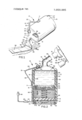
- FIG. 2 is a longitudinal sectional view of the applicator and an exploded view showing alternative dispenser heads.
- FIG. 1 a hair removing applicator 10 is shown which includes a relatively large container 11 having an upper portion 12 and a lower portion 13.
- Containerv 11 has a closed and slightly sloped top wall 14 and a generally open bottom 15.
- the container upper portion 12 tenninates in a dispenser neck 16 having an erect portion 17 and an offset portion 18 inclined relative to the longitudinal axis of the container 11.
- a removable cap 19 is secured within an opening formed in the top wall 14 of the container upper portion 12.
- the cap 19 has a finger grip 20 to facilitate removing the cap from its closed position and explained.
- a variable sized chamber 25 formed within container 11 holds a supply of hairremover adhesive 26 which is preferably beeswax.
- An electrical cord 27 supplys current from an external sour-ce'tola heating means-within container 11;
- dispenser head 30'l Removablycoupled to dispenser neck 16 is a dispenser head 30'lwhich has a coupling portion 31, and a relatively large flaring nozzle 32.
- 'Applicator 10 is shown being maneuverd in a direc- ..tion indicatedby directionalarrow D while extruding a ribbon 38 of beeswax .onto'a hair growth area 39.-A
- Plunger 46 has aninner or concealed face 48 and an outer or generally exposed face 49 formed with a hand
- the heating means 60' is partially imbedded or mounted within the stru'ctureof container ll and ineludes an electrical resistanceheating'coil wound sinuously throughout at least the upper region of container upper portion 12-.
- a coil segment 61 is shown on oneside connected'to electrical cord 27 and another coil'segment 62 is shown on the other 'side of container upper portion 12.
- the external electrical cord 27 is coupled through an on/off switch 63 to-an'electrical plug 64.
- Switch 63*inclu'des heat control means such as a thermostat.
- the operator, priorto applying' beeswax to a hair growth area may choose a dispenser head 30 with a relatively wide exit slit 33 or may select'a different dispenser head 68 with a converging'nozzle 69 and a relatively narrow exit slit 70.v
- Thehandle'2l . is constructed so that when the bar 22' is maintainedsubstantially horizontal thenthe. dispensing-neck offset portion 18 will be held relatively vertical to betteraim and spread extruding beeswax.
- dispenser head'30 would be selected.
- Plunger 46 is rotated in a direction towards dispenser grip 50'-that' may be manipulated clockwise-or counter-' clockwise to drive the plunger axially as indicated by directional arrow X; Rotation of plunger 46 in one direction advances it towards container top wall 14 while rotation in'the opposite direction retracts plunger 46 outwardly or towards bottom wall 15.
- the sidewalls,of-container 11 are formed internally with an ann'ularshoulder 51 defining the bottom region of a relatively enlarged or thick upper wall segment 52 having a smoothbore interior wall.
- piston 54 Arranged between container top wall 14 and plunger 46'is a piston 54 having a slightly cupped shape constituted by side wall 55 that is sized and positioned for slidable engagement'over and along the smooth bore segment 52 which is fully within variable chamber 25.
- a suitable biasing means 56 is interposed between and engaged by both of the plunger46 and piston 54.
- the biasing means is shown in the form of a high energy coil spring 56 whose'opposite ends are in contact with the center regions of plunger 46 and piston 54. Piston axial movement is indicated by directional arrow Y.
- spring pressure exerted on piston 54' is increased to cause a correspondingly increased pressure on the beeswax 26.
- the hair remover adhesive or beeswax 26 is dropped into variable chamber 25 through hole 44 in the form of pieces or chunks 58.
- Thermal action by the heating means 60 .causes at least some of the beeswax 26 to become melted beeswax 59.
- Electrical switch 63 is turned on to thereby energize heating means60 which eventuallycauses at least some of the beeswax 59- to become'melted'or atleast transformed into asemi'JiqUid-plastic flow state.
- heating means60 which eventuallycauses at least some of the beeswax 59- to become'melted'or atleast transformed into asemi'JiqUid-plastic flow state.
- the operator may periodically rotate plunger46' to achieve a relativelysteady pressure on the melted beeswax in variable chamber 25.
- the mass flow rate of the extruding beeswax 37 may be regulated by manipulating plunger 46 to increase'or decrease pressure.
- the applicator l0 is'traversed across the hair growth area 39 with a steady motion.
- the beeswax satisfactory or optimum temperature for application to the hair growth area may be in the range of between 1 l5l30.
- the beauty salon operator may peel off the ribbon or strip 38 of beeswax which will simultaneously remove hairs 44 adhesively imbedded within the mass of beeswax.
- An applicator for dispensing and spreading hair remover adhesive onto a hair growth area comprising:
- a piston slidably positioned within the container and arranged for movement along the longitudinal axis of the container;
- a plunger with external threads inter-engaged with the internal threads of the container lower portion, so the plunger may be selectively advanced towards the container upper portion or retracted;
- biasing means interposed between and engaging both the piston and the plunger so that pressure exerted on the piston by the biasing means may be selectively increased or decreased as the plunger is advanced and retracted respectively;
- heating means in the container upper portion adjacent the variable chamber in order to melt the hair remover adhesive, the heating means including an electrical wire wound substantially throughout a segment of the container upper portion to fully surround a segment of the variable chamber, and, a switch connected to the electrical wire so heating may be selectively initiated and terminated;
- a dispensing head removably coupled to the dispensing neck for dispensing and spreading melted hair remover adhesive onto a hair growth area when melted hair remover adhesive is extruded through the dispensing head under pressure from the piston and/or gravitational force;
- a handle connected to a side of the container and having a grasping bar arranged in a manner so that when held substantially horizontal it serves to maintain the dispensing neck outermost part in a substantially erect position for best dispensing and spreading melted hair remover adhesive.
- the biasing means is a coiled spring extending approximately between the centers of the plunger and piston.
- the inner face of the plunger is attached to the coiled spring and the outer face of the plunger is formed with a hand grip to facilitate advancing and retracting the plunger.
- a removable cap secured within an opening in the container upper portion, through which new pieces or charges of hair remover adhesive may be deposited into the variable chamber.
- the dispensing neck bears threads to removably hold one of multiple and selectively interchangeable dispensing heads.
Landscapes
- Coating Apparatus (AREA)
Abstract
An applicator for dispensing and spreading hair remover adhesive such as beeswax includes a variable size chamber in which solid or semi-solid hair remover adhesive can be selectively heated to optimum extrudable conditions. The mass flow rate at which ribbons of hair remover adhesive is extruded onto a hair growth area, can be regulated by adjusting the biasing force exerted on a spring loaded piston. Application of the adhesive proceeds neatly and quickly.
Description
United States Patent 1191 Fiveash [5 11A1R REMOVING APPLICATOR AND PROCESS [76] Inventor: Daniel Enoch Fiveash', 11927 Culver Blvd, No. 10, Los Angeles, Calif. 90066 [22] Filed: May 4, 1973 [21] Appl. No.1 357,237
[52] U.S. Cl. 401/2, 222/146 HE, 128/355,
40l/l72;180 [51] Int. Cl .[A47l 13/32 [58] Field of Search 401/1, 2, 180, 171-175;
[56] References Cited UNITED STATES PATENTS 1,312,347 8/1919 Ogden "401/2 1,333,458 3/1920 Sorver 1,754,330 4/1930 Litomy 222/146 HE 1 1 Jan, 7., 1975 1,920,629 8/1933 Chevassus 401/2 2,118,953 5/1938 Thiecker 222/146 HE x 2,272,780 2/1942 Schweyer 401/2 FOREIGN PATENTS OR APPLICATIONS 430,014 2/1948 ltaly 401/180 Primary ExaminerLawrence Charles Attorney, Agent, or Firm-Pastoriza & Kelly 57 ABSTRACT -An applicator for dispensing and spreading hair re mover adhesive such as beeswax includes a variable size chamber in which solid or semi-solid hair remover adhesive can be selectively heated to optimum extrudable conditions. The mass flow rate at which ribbons of hair remover adhesive is extruded onto a hair growth area, can be regulated by adjusting the biasing force exerted on a spring loaded piston. Application of the adhesive proceeds neatly and quickly.
5 Claims, 2 Drawing Figures a 1 HAIR REMOVING APPLICATOR AND PROCESS BACKGROUND OF THE INVENTION This invention generally relates to techniques for the removal of hair from hair growth areas and more specifically pertains to the removal of human hair from arms and legs for example, through the application and stripping away of some suitable hair remover adhesive such as beeswax.
Customary methods for removing hair from human limbs at beauty salons for example are generally untidy, time consuming and cumbersome.
The person is positioned on an underlying disposable sheet such as wax paper. Hair remover adhesive which is ordinarily beeswax is heated in a relatively large container on a stove or hot plate and then a portion of the heated beeswax is deposited into a smaller portable container and permitted to cool. In the meanwhile the person hasher hair growth areaof interest braced and prepared by powder or oil.
When the beauty salon operator determines that the beeswax is cool enough than a pan of melted adhesive is held in one hand while a spoon, paddle or spatula is held in the other hand. Melted adhesive is dripped or deposited onto the customers hair growth area while the spoon, etc., is used to simultaneously spread the ad- I hesive into an overlying layer. If the layeris too thin then it will chip when attempts are made to remove it. If the layer is spread too thick then beeswax is wasted and it becomes extra time consuming to await for the beeswax to properly set.
When the layer of beeswax has properly cooledand set then it is stripped away by the-beauty salon operator along with the imbedded hairs which thereby become SUMMARY OF THE INVENTION Briefly stated this invention concerns an applicator constructed so as to greatly facilitate applying melted beeswax onto the hair growth area of a person with greatly minimized messiness and annoyance. The procedure of removing hair employing the applicator of this invention is relatively quick, dependable and easy to perform.
The hair removing applicator of this invention generally operates to dispense and also spread hair remover adhesive onto the hair growth area of a person such as a person's limbs. A container has an upper portion formed with a dispensing neck and a lower portion which is generally open and formed with internal threads. A piston is slidably positioned within the container and is arranged for movement along the longitudinal axis of the container. I
A variable chamber for holding hair remover adhesive such as beeswax is formed or constituted by coacting surfaces of'the container and the piston. A plunger has external threads that are interengaged with the internal threads of the container lower portion. The
plunger can be'selectively advanced towards the container upper portion or retracted towards the container bottom end. Biasing means is interposed between and engages both of the piston and plunger so that pressure exerted on the piston by the biasing means can be selectively increased or decreased by advancing and retracting the plunger respectively.
Heating means is located within the container upper portion adjacent the variable chamber to melt the hair remover adhesive to a suitable temperature and consistency. A dispensing head is removably coupled to the dispensing neck in order to dispense and spread melted hair remover adhesive onto the hair growth area. Melted adhesive may be extruded through the dispensing head under pressure from the piston or pressure from both the piston and gravitational force.
From a process standpoint, this invention involves a procedure for removing hair from a hair growth area of a certain width and includes the step of depositing solid or semi-solid pieces of hair remover adhesive into a chamber of the applicator. A dispensing head is selected with an exit slit length substantially equal to the given or certain width of the hair growth area to be treated. The solid or semi-solid pieces of hair remover adhesive are heated in the chamber to a melted condition and optimum temperature.
Thereafter the applicator is traversed along the hair growth area and a ribbon of melted hair remover adhesive is extruded in a constant width through the dispensing head exit slit and onto the hair growth area.
After the ribbon of adhesive has cooled sufficiently then the ribbon is stripped away along with the adhered and imbedded hairsin order to remove all or some of the hairs from the hair growth area.
Preferably the hair remover adhesive is beeswax. Pressure on the melted hair remover adhesive may be increased and decreased in order to increase and decrease respectively the mass flow rate of the adhesive ribbon being extruded.
BRIEF DESCRIPTION OF THE DRAWINGS The numerous benefits and unique aspects of the present invention will be fully understood when the following detailed description is studied in conjunction with the drawings in which:
FIG. 1 is a perspective partly schematic view showing a hair remover applicator constructed in accordance with this invention being used to dispense adhesive onto a hair growth area; 7
FIG. 2 is a longitudinal sectional view of the applicator and an exploded view showing alternative dispenser heads.
DETAILED DESCRIPTION OF THE PREFERRED EMBODIMENT Referring now primarily to FIG. 1 a hair removing applicator 10 is shown which includes a relatively large container 11 having an upper portion 12 and a lower portion 13. Containerv 11 has a closed and slightly sloped top wall 14 and a generally open bottom 15.
The container upper portion 12 tenninates in a dispenser neck 16 having an erect portion 17 and an offset portion 18 inclined relative to the longitudinal axis of the container 11. A removable cap 19 is secured within an opening formed in the top wall 14 of the container upper portion 12. The cap 19 has a finger grip 20 to facilitate removing the cap from its closed position and explained. r
of'container 11 is ahandle 21 havanother bar 23.
allow new charges of hairremover, adhesive tobe deposited into the container 11 for a purpose that-shall be Attached to a side ing-a'relatively longbar 22 for grasping by a person and A variable sized chamber 25 formed within container 11 holds a supply of hairremover adhesive 26 which is preferably beeswax. An electrical cord 27 supplys current from an external sour-ce'tola heating means-within container 11;
Removablycoupled to dispenser neck 16 is a dispenser head 30'lwhich has a coupling portion 31, and a relatively large flaring nozzle 32.
'Applicator 10 is shown being maneuverd in a direc- ..tion indicatedby directionalarrow D while extruding a ribbon 38 of beeswax .onto'a hair growth area 39.-A
relatively wide band 37 of beeswax is shown being exv to the dispenser head coupled to the externally formed threads 43 on the offset portion 18. A'hole'44 in top wall 14'is threadedto receive and seal removable cap 19. The removablecap 19 could alternatively be a cork plug. The internal wall wardly of bottom rim 15,.is formed with threads 45;. A disk shaped 'plunger 46 is formed with external threads 47 shaped to interengage with mating threads- 45. Plunger 46; has aninner or concealed face 48 and an outer or generally exposed face 49 formed with a hand The heating means 60' is partially imbedded or mounted within the stru'ctureof container ll and ineludes an electrical resistanceheating'coil wound sinuously throughout at least the upper region of container upper portion 12-. For illustration purposes a coil segment 61 is shown on oneside connected'to electrical cord 27 and another coil'segment 62 is shown on the other 'side of container upper portion 12. The external electrical cord 27 is coupled through an on/off switch 63 to-an'electrical plug 64. Switch 63*inclu'des heat control means such as a thermostat.
The operator, priorto applying' beeswax to a hair growth area may choose a dispenser head 30 with a relatively wide exit slit 33 or may select'a different dispenser head 68 with a converging'nozzle 69 and a relatively narrow exit slit 70.v
Thehandle'2l .is constructed so that when the bar 22' is maintainedsubstantially horizontal thenthe. dispensing-neck offset portion 18 will be held relatively vertical to betteraim and spread extruding beeswax.
i OPERATION Keeping the. above-construction in mind it can 'be un- I ,derstood howpreviously described disadvantages of a dispense'r head 30 017 68 for exa'mple'with an exit slit' of container lower portion 13, in.-
conventional hair removingtechniques are overcome or substantiallyeliminated by this invention. 1
[Initially the beauty salon operator or the like selects having a .width suitable to accomodate the hair growth area 39 to be. treated. Due to the size of the hair growth area 39 or other considerations it maybe desirable to apply arelativelynarrow .ribbonof hair remover adhesive, in whichcase dispenser head 68 would be chosen,'
or a relatively wide ribbon of hair remover adhesive, in which case dispenser head'30 would be selected.
. j Plunger 46is rotated in a direction towards dispenser grip 50'-that' may be manipulated clockwise-or counter-' clockwise to drive the plunger axially as indicated by directional arrow X; Rotation of plunger 46 in one direction advances it towards container top wall 14 while rotation in'the opposite direction retracts plunger 46 outwardly or towards bottom wall 15.
'The sidewalls,of-container 11 are formed internally with an ann'ularshoulder 51 defining the bottom region ofa relatively enlarged or thick upper wall segment 52 having a smoothbore interior wall.
Arranged between container top wall 14 and plunger 46'is a piston 54 having a slightly cupped shape constituted by side wall 55 that is sized and positioned for slidable engagement'over and along the smooth bore segment 52 which is fully within variable chamber 25.
A suitable biasing means 56 is interposed between and engaged by both of the plunger46 and piston 54. The biasing means is shown in the form of a high energy coil spring 56 whose'opposite ends are in contact with the center regions of plunger 46 and piston 54. Piston axial movement is indicated by directional arrow Y.
By twisting hand grip 50 to advance plunger 46,
spring pressure exerted on piston 54' is increased to cause a correspondingly increased pressure on the beeswax 26.
Initially the hair remover adhesive or beeswax 26 is dropped into variable chamber 25 through hole 44 in the form of pieces or chunks 58. Thermal action by the heating means 60 .causes at least some of the beeswax 26 to become melted beeswax 59.
neck 16 causing coil'sprin'g 56'to compress and exert progressively greater force against piston 54.v
Electrical switch 63 is turned on to thereby energize heating means60 which eventuallycauses at least some of the beeswax 59- to become'melted'or atleast transformed into asemi'JiqUid-plastic flow state. As a result of thecompressive'force transmitted to the melted or semi-liquid beeswax 59:by piston 54,.the beeswax commences being extruded through the dispenser-neck l6 and associated'di'spenser head 30 for example. Beeswax '37 is extruded through the narrow exit slit 33 and onto the hair growth area 39 in the form of 'a ribbon 38 of constant width.
To maintain a desired massflow rate the operator may periodically rotate plunger46' to achieve a relativelysteady pressure on the melted beeswax in variable chamber 25. The mass flow rate of the extruding beeswax 37 may be regulated by manipulating plunger 46 to increase'or decrease pressure.
The applicator l0 is'traversed across the hair growth area 39 with a steady motion. The beeswax satisfactory or optimum temperature for application to the hair growth areamay be in the range of between 1 l5l30.
' After the ribbon 38 of beeswax has cooled, in 15 to 25 seconds for example, then the beauty salon operator may peel off the ribbon or strip 38 of beeswax which will simultaneously remove hairs 44 adhesively imbedded within the mass of beeswax.
-As the operator terminates extruding beeswax and prepares to complete the hair removing procedure, she may rotate the plunger46 in an opposite direction to relax pressure on the beeswax 26. Any excess beeswax within head 30 and dispensing neck 16 will be permitted to drain backwardly into chamber 25 for reuse. This will prevent beeswax from hardening and clogging within the passageways.
From the forgoing it will be evident that the present invention has provided a hair removing applicator and process in which all of the various advantages are fully realized.
What is claimed is:
1. An applicator for dispensing and spreading hair remover adhesive onto a hair growth area, comprising:
a. a container having an upper portion formed with a dispensing neck and a lower portion that is generally open and formed with internal threads;
b. a piston slidably positioned within the container and arranged for movement along the longitudinal axis of the container;
c. a variable chamber formed by the container and the piston;
d. a supply of hair remover adhesive in the variable chamber;
e. a plunger with external threads inter-engaged with the internal threads of the container lower portion, so the plunger may be selectively advanced towards the container upper portion or retracted;
f. biasing means interposed between and engaging both the piston and the plunger so that pressure exerted on the piston by the biasing means may be selectively increased or decreased as the plunger is advanced and retracted respectively;
g. heating means in the container upper portion adjacent the variable chamber in order to melt the hair remover adhesive, the heating means including an electrical wire wound substantially throughout a segment of the container upper portion to fully surround a segment of the variable chamber, and, a switch connected to the electrical wire so heating may be selectively initiated and terminated;
h. a dispensing head removably coupled to the dispensing neck for dispensing and spreading melted hair remover adhesive onto a hair growth area when melted hair remover adhesive is extruded through the dispensing head under pressure from the piston and/or gravitational force;
i. an outermost part of the dispensing neck offset and inclined away from the axis of the container; and
j. a handle connected to a side of the container and having a grasping bar arranged in a manner so that when held substantially horizontal it serves to maintain the dispensing neck outermost part in a substantially erect position for best dispensing and spreading melted hair remover adhesive.
2. The structure according to claim 1 wherein:
the biasing means is a coiled spring extending approximately between the centers of the plunger and piston.
3. The structure according to claim 2 wherein:
the inner face of the plunger is attached to the coiled spring and the outer face of the plunger is formed with a hand grip to facilitate advancing and retracting the plunger.
4. The structure according to claim 1 including:
a removable cap secured within an opening in the container upper portion, through which new pieces or charges of hair remover adhesive may be deposited into the variable chamber.
5. The structure according to claim 1 wherein;
the dispensing neck bears threads to removably hold one of multiple and selectively interchangeable dispensing heads.
Claims (5)
1. An applicator for dispensing and spreading hair remover adhesive onto a hair growth area, comprising: a. a container having an upper portion formed with a dispensing neck and a lower portion that is generally open and formed with internal threads; b. a piston slidably positioned within the container and arranged for movement along the longitudinal axis of the container; c. a variable chamber formed by the container and the piston; d. a supply of hair remover adhesive in the variable chamber; e. a plunger with external threads inter-engaged with the internal threads of the container lower portion, so the plunger may be selectively advanced towards the container upper portion or retracted; f. biasing means interposed between and engaging both the piston and the plunger so that pressure exerted on the piston by the biasing means may be selectively increased or decreased as the plunger is advanced and retracted respectively; g. heating means in the container upper portion adjacent the variable chamber in order to melt the hair remover adhesive, the heating means including an electrical wire wound substantially throughout a segment of the container upper portion to fully surround a segment of the variable chamber, and, a switch connected to the electrical wire so heating may be selectively initiated and terminateD; h. a dispensing head removably coupled to the dispensing neck for dispensing and spreading melted hair remover adhesive onto a hair growth area when melted hair remover adhesive is extruded through the dispensing head under pressure from the piston and/or gravitational force; i. an outermost part of the dispensing neck offset and inclined away from the axis of the container; and j. a handle connected to a side of the container and having a grasping bar arranged in a manner so that when held substantially horizontal it serves to maintain the dispensing neck outermost part in a substantially erect position for best dispensing and spreading melted hair remover adhesive.
2. The structure according to claim 1 wherein: the biasing means is a coiled spring extending approximately between the centers of the plunger and piston.
3. The structure according to claim 2 wherein: the inner face of the plunger is attached to the coiled spring and the outer face of the plunger is formed with a hand grip to facilitate advancing and retracting the plunger.
4. The structure according to claim 1 including: a removable cap secured within an opening in the container upper portion, through which new pieces or charges of hair remover adhesive may be deposited into the variable chamber.
5. The structure according to claim 1 wherein; the dispensing neck bears threads to removably hold one of multiple and selectively interchangeable dispensing heads.
Priority Applications (1)
| Application Number | Priority Date | Filing Date | Title |
|---|---|---|---|
| US357237A US3858985A (en) | 1973-05-04 | 1973-05-04 | Hair removing applicator and process |
Applications Claiming Priority (1)
| Application Number | Priority Date | Filing Date | Title |
|---|---|---|---|
| US357237A US3858985A (en) | 1973-05-04 | 1973-05-04 | Hair removing applicator and process |
Publications (1)
| Publication Number | Publication Date |
|---|---|
| US3858985A true US3858985A (en) | 1975-01-07 |
Family
ID=23404831
Family Applications (1)
| Application Number | Title | Priority Date | Filing Date |
|---|---|---|---|
| US357237A Expired - Lifetime US3858985A (en) | 1973-05-04 | 1973-05-04 | Hair removing applicator and process |
Country Status (1)
| Country | Link |
|---|---|
| US (1) | US3858985A (en) |
Cited By (43)
| Publication number | Priority date | Publication date | Assignee | Title |
|---|---|---|---|---|
| FR2339359A1 (en) * | 1976-01-29 | 1977-08-26 | Vercelletti Guy | Manual electrical apparatus to melt depilation wax - is fitted with heated reservoir which is opened and closed by valve |
| FR2495906A1 (en) * | 1980-12-12 | 1982-06-18 | Seb Sa | APPARATUS FOR CLEARING WAX, IN PARTICULAR FOR THE FACE |
| DE3242001A1 (en) * | 1982-01-29 | 1983-08-04 | Inverness International Corp., 07661 River Edge, N.J. | WAX CARRIER |
| US4499367A (en) * | 1982-06-16 | 1985-02-12 | Seb S.A. | Device and method for wax depilation |
| FR2593043A1 (en) * | 1986-01-22 | 1987-07-24 | Seb Sa | WAXING DEVICE WITH WAX. |
| US4682950A (en) * | 1985-10-30 | 1987-07-28 | Dragan William B | Device and method of bonding and veneering dental material to a tooth |
| EP0273495A2 (en) * | 1986-12-03 | 1988-07-06 | Koninklijke Philips Electronics N.V. | Depilating apparatus |
| US4773784A (en) * | 1982-01-29 | 1988-09-27 | Inverness Corporation | Hot wax hair remover apparatus |
| EP0298043A1 (en) * | 1987-04-06 | 1989-01-04 | Ugo Nazzarro | Depilatory wax automatic dispenser on depilatory strips |
| US4958951A (en) * | 1982-01-29 | 1990-09-25 | Inverness Corporation | Hot wax hair remover apparatus |
| FR2659204A3 (en) * | 1990-03-06 | 1991-09-13 | Ceraboma Sa Lab | Wax applicator for hair removal |
| US5188256A (en) * | 1990-08-06 | 1993-02-23 | Nottingham-Spirk Design Associates, Inc. | Method of heating and dispensing hot melt materials that employs microwave energy |
| EP0592340A1 (en) * | 1992-10-09 | 1994-04-13 | Seb S.A. | Applicator for hot melt products, in particular depilatory wax, with a heating container |
| US5368199A (en) * | 1990-08-06 | 1994-11-29 | Loctite Corporation | Microwaveable hot melt dispenser |
| US5556468A (en) * | 1993-06-14 | 1996-09-17 | Seb S.A. | Applicator for meltable products, in particular depilatory wax |
| US5873666A (en) * | 1994-06-23 | 1999-02-23 | Bourke; Jane Vanessa | Wax applicator |
| US5980536A (en) * | 1998-03-23 | 1999-11-09 | Jamali; Parvin | Wax container and application kit |
| US6053649A (en) * | 1997-09-25 | 2000-04-25 | Ronai; Christian | Wax warmer and applicator apparatus |
| US6174319B1 (en) * | 1996-12-20 | 2001-01-16 | Reckitt Benckiser France | Hair removal containers and devices incorporating a thermochromic indicator |
| GB2375709A (en) * | 2001-04-26 | 2002-11-27 | Francis O'hare | Depilatory wax applicator with a flared spreader and integrated funnel mouth |
| WO2003030677A1 (en) * | 2001-10-11 | 2003-04-17 | Faco S.A. | Depilatory wax applicator |
| US20030165793A1 (en) * | 2001-10-27 | 2003-09-04 | Dan Yobel | System for dispensing viscous materials |
| ES2212880A1 (en) * | 2002-03-14 | 2004-08-01 | Juan Francesc Casas Boncompte | Static machine for applying depilatory wax to remove hair in e.g. women, at aesthetic and beauty center, has heating device and applicator element obtaining wax from wax tank through conduit, where device is provided with thermal sources |
| FR2850546A1 (en) * | 2003-01-31 | 2004-08-06 | Cosmetologie Moderne Lab De | Applicator for depilation wax, suitable for use at any angle to the horizontal, comprising elongated wax container with application roller head and movable piston to force wax towards roller |
| US20050010086A1 (en) * | 2002-06-12 | 2005-01-13 | Dominique Vanneste | Process methods and apparatus for removing non-adherent elements for the skin of living beings, for measuring the hair loss of living beings, for measuring a quality sacle of a manufactured product and for having the pattern of non-adherent elements on a surface |
| US20050170313A1 (en) * | 2002-03-01 | 2005-08-04 | Pitz Richard J. | System for dispensing viscous materials |
| US20080004635A1 (en) * | 2006-06-16 | 2008-01-03 | Mcmillan Anna | Hair removal appliance and method of using same |
| US20080142495A1 (en) * | 2005-01-12 | 2008-06-19 | Des Garets Christian | Cosmetic Product Applicators, Particularly a Device for Spreading a Hair Remover Wax on the Skin Thereof |
| US20080240838A1 (en) * | 2005-11-07 | 2008-10-02 | Ceras Especiales Martinez De San Vicente, S.A. | Procedure and System for Dispensing Depilatory Wax in a Regulated Manner for its Immediate Application |
| US20090136282A1 (en) * | 2007-11-23 | 2009-05-28 | Tarajee Brown | Disposable Body Wax Applicator System and Method |
| US8021315B1 (en) * | 2006-12-06 | 2011-09-20 | Mceneaney Kimberly | Fingertip protecting device |
| WO2011115971A1 (en) | 2010-03-15 | 2011-09-22 | The Gillette Company | Hair removal device |
| WO2011130372A1 (en) | 2010-04-15 | 2011-10-20 | The Procter & Gamble Company | Fluid dispensing hair removal device |
| WO2012058216A2 (en) | 2010-10-27 | 2012-05-03 | The Gillette Company | Composition dispensing device comprising a non-foaming hydrating composition |
| WO2013025772A2 (en) | 2011-08-16 | 2013-02-21 | The Gillette Company | Composition dispensing device comprising a moisturizing composition |
| AU2008202894B2 (en) * | 2007-07-03 | 2013-11-07 | Mancine Cosmetics Pty Ltd | Depilatory wax dispenser |
| US20140236182A1 (en) * | 2013-02-16 | 2014-08-21 | Susan Lyda Reynolds | Device and Method For Removing Unwanted Hair |
| US20150382401A1 (en) * | 2014-06-26 | 2015-12-31 | Wilfried Dietz | Heated Utensil Kit System |
| EP3111995A1 (en) | 2015-06-30 | 2017-01-04 | The Gillette Company LLC | Liquid compositions for hair removal devices |
| US9604243B1 (en) | 2015-09-09 | 2017-03-28 | GLS Products, LLC | Adhesive dispenser |
| WO2018009742A1 (en) | 2016-07-08 | 2018-01-11 | The Gillette Company Llc | Liquid compositions for hair removal devices comprising metathesized unsaturated polyol esters |
| WO2018142412A1 (en) * | 2017-02-05 | 2018-08-09 | HALFON, Liran Yehiel | Waxing apparatus |
| US20230296256A1 (en) * | 2022-03-16 | 2023-09-21 | Michael Misiolek | Wax melting pot |
Citations (6)
| Publication number | Priority date | Publication date | Assignee | Title |
|---|---|---|---|---|
| US1312347A (en) * | 1919-08-05 | Sealing wax | ||
| US1333458A (en) * | 1918-09-19 | 1920-03-09 | Robert D Sorver | Electric sealer |
| US1754330A (en) * | 1928-07-06 | 1930-04-15 | John L Litomy | Outlining implement for surface-ornamenting processes |
| US1920629A (en) * | 1930-05-10 | 1933-08-01 | Chevassus Gustave | Device for melting wax disks |
| US2118953A (en) * | 1936-11-18 | 1938-05-31 | Western Electric Co | Container |
| US2272780A (en) * | 1939-06-12 | 1942-02-10 | Daniel H Schweyer | Thermoelectric marker |
-
1973
- 1973-05-04 US US357237A patent/US3858985A/en not_active Expired - Lifetime
Patent Citations (6)
| Publication number | Priority date | Publication date | Assignee | Title |
|---|---|---|---|---|
| US1312347A (en) * | 1919-08-05 | Sealing wax | ||
| US1333458A (en) * | 1918-09-19 | 1920-03-09 | Robert D Sorver | Electric sealer |
| US1754330A (en) * | 1928-07-06 | 1930-04-15 | John L Litomy | Outlining implement for surface-ornamenting processes |
| US1920629A (en) * | 1930-05-10 | 1933-08-01 | Chevassus Gustave | Device for melting wax disks |
| US2118953A (en) * | 1936-11-18 | 1938-05-31 | Western Electric Co | Container |
| US2272780A (en) * | 1939-06-12 | 1942-02-10 | Daniel H Schweyer | Thermoelectric marker |
Cited By (60)
| Publication number | Priority date | Publication date | Assignee | Title |
|---|---|---|---|---|
| FR2339359A1 (en) * | 1976-01-29 | 1977-08-26 | Vercelletti Guy | Manual electrical apparatus to melt depilation wax - is fitted with heated reservoir which is opened and closed by valve |
| FR2495906A1 (en) * | 1980-12-12 | 1982-06-18 | Seb Sa | APPARATUS FOR CLEARING WAX, IN PARTICULAR FOR THE FACE |
| EP0055157A1 (en) * | 1980-12-12 | 1982-06-30 | Seb S.A. | Apparatus for depilating with wax, in particular for the face |
| US4465073A (en) * | 1980-12-12 | 1984-08-14 | Seb S.A. | Appliance for wax depilation, especially for facial use |
| US4773784A (en) * | 1982-01-29 | 1988-09-27 | Inverness Corporation | Hot wax hair remover apparatus |
| FR2520601A1 (en) * | 1982-01-29 | 1983-08-05 | Inverness Int | HOT WAX APPLICATOR ASSEMBLY FOR CLEANING AND METHOD FOR APPLYING SAID WAX |
| DE3242001A1 (en) * | 1982-01-29 | 1983-08-04 | Inverness International Corp., 07661 River Edge, N.J. | WAX CARRIER |
| US4958951A (en) * | 1982-01-29 | 1990-09-25 | Inverness Corporation | Hot wax hair remover apparatus |
| DE3242001C2 (en) * | 1982-01-29 | 1990-12-06 | Inverness International Corp., River Edge, N.J., Us | |
| DE3249972C2 (en) * | 1982-01-29 | 1993-08-05 | Inverness Corp., Fair Lawn, N.J., Us | |
| US4499367A (en) * | 1982-06-16 | 1985-02-12 | Seb S.A. | Device and method for wax depilation |
| US4682950A (en) * | 1985-10-30 | 1987-07-28 | Dragan William B | Device and method of bonding and veneering dental material to a tooth |
| FR2593043A1 (en) * | 1986-01-22 | 1987-07-24 | Seb Sa | WAXING DEVICE WITH WAX. |
| EP0234975A1 (en) * | 1986-01-22 | 1987-09-02 | Seb S.A. | Wax epilation device |
| EP0273495A3 (en) * | 1986-12-03 | 1988-07-20 | N.V. Philips' Gloeilampenfabrieken | Depilating apparatus |
| EP0273495A2 (en) * | 1986-12-03 | 1988-07-06 | Koninklijke Philips Electronics N.V. | Depilating apparatus |
| EP0298043A1 (en) * | 1987-04-06 | 1989-01-04 | Ugo Nazzarro | Depilatory wax automatic dispenser on depilatory strips |
| FR2659204A3 (en) * | 1990-03-06 | 1991-09-13 | Ceraboma Sa Lab | Wax applicator for hair removal |
| US5368199A (en) * | 1990-08-06 | 1994-11-29 | Loctite Corporation | Microwaveable hot melt dispenser |
| US5188256A (en) * | 1990-08-06 | 1993-02-23 | Nottingham-Spirk Design Associates, Inc. | Method of heating and dispensing hot melt materials that employs microwave energy |
| EP0592340A1 (en) * | 1992-10-09 | 1994-04-13 | Seb S.A. | Applicator for hot melt products, in particular depilatory wax, with a heating container |
| FR2696659A1 (en) * | 1992-10-09 | 1994-04-15 | Seb Sa | Applicator for hot melt products, in particular depilatory wax, with a heating tank. |
| US5395175A (en) * | 1992-10-09 | 1995-03-07 | Seb S.A. | Dispenser having a heating reservoir for thermoplastic products, in particular depilatory wax |
| US5556468A (en) * | 1993-06-14 | 1996-09-17 | Seb S.A. | Applicator for meltable products, in particular depilatory wax |
| US5681388A (en) * | 1993-06-14 | 1997-10-28 | Seb S.A. | Applicator for meltable products, in particular depilatory wax |
| US5846326A (en) * | 1993-06-14 | 1998-12-08 | Seb S.A. | Applicator for meltable products in particular depilatory wax |
| US5873666A (en) * | 1994-06-23 | 1999-02-23 | Bourke; Jane Vanessa | Wax applicator |
| US6174319B1 (en) * | 1996-12-20 | 2001-01-16 | Reckitt Benckiser France | Hair removal containers and devices incorporating a thermochromic indicator |
| US6053649A (en) * | 1997-09-25 | 2000-04-25 | Ronai; Christian | Wax warmer and applicator apparatus |
| US5980536A (en) * | 1998-03-23 | 1999-11-09 | Jamali; Parvin | Wax container and application kit |
| GB2375709A (en) * | 2001-04-26 | 2002-11-27 | Francis O'hare | Depilatory wax applicator with a flared spreader and integrated funnel mouth |
| GB2375709B (en) * | 2001-04-26 | 2004-06-30 | Francis O'hare | Depilatory wax applicator |
| WO2003030677A1 (en) * | 2001-10-11 | 2003-04-17 | Faco S.A. | Depilatory wax applicator |
| US20030165793A1 (en) * | 2001-10-27 | 2003-09-04 | Dan Yobel | System for dispensing viscous materials |
| US20050170313A1 (en) * | 2002-03-01 | 2005-08-04 | Pitz Richard J. | System for dispensing viscous materials |
| US7086861B2 (en) * | 2002-03-01 | 2006-08-08 | Pitz Richard J | System for dispensing viscous materials |
| ES2212880A1 (en) * | 2002-03-14 | 2004-08-01 | Juan Francesc Casas Boncompte | Static machine for applying depilatory wax to remove hair in e.g. women, at aesthetic and beauty center, has heating device and applicator element obtaining wax from wax tank through conduit, where device is provided with thermal sources |
| US20050010086A1 (en) * | 2002-06-12 | 2005-01-13 | Dominique Vanneste | Process methods and apparatus for removing non-adherent elements for the skin of living beings, for measuring the hair loss of living beings, for measuring a quality sacle of a manufactured product and for having the pattern of non-adherent elements on a surface |
| FR2850546A1 (en) * | 2003-01-31 | 2004-08-06 | Cosmetologie Moderne Lab De | Applicator for depilation wax, suitable for use at any angle to the horizontal, comprising elongated wax container with application roller head and movable piston to force wax towards roller |
| US20080142495A1 (en) * | 2005-01-12 | 2008-06-19 | Des Garets Christian | Cosmetic Product Applicators, Particularly a Device for Spreading a Hair Remover Wax on the Skin Thereof |
| US8567644B2 (en) * | 2005-11-07 | 2013-10-29 | Ceras Especiales Martinez De San Vicente, S.A. | Procedure and system for dispensing depilatory wax in a regulated manner for its immediate application |
| US20080240838A1 (en) * | 2005-11-07 | 2008-10-02 | Ceras Especiales Martinez De San Vicente, S.A. | Procedure and System for Dispensing Depilatory Wax in a Regulated Manner for its Immediate Application |
| US20080004635A1 (en) * | 2006-06-16 | 2008-01-03 | Mcmillan Anna | Hair removal appliance and method of using same |
| US8021315B1 (en) * | 2006-12-06 | 2011-09-20 | Mceneaney Kimberly | Fingertip protecting device |
| AU2008202894B2 (en) * | 2007-07-03 | 2013-11-07 | Mancine Cosmetics Pty Ltd | Depilatory wax dispenser |
| US20090136282A1 (en) * | 2007-11-23 | 2009-05-28 | Tarajee Brown | Disposable Body Wax Applicator System and Method |
| WO2011115971A1 (en) | 2010-03-15 | 2011-09-22 | The Gillette Company | Hair removal device |
| WO2011130372A1 (en) | 2010-04-15 | 2011-10-20 | The Procter & Gamble Company | Fluid dispensing hair removal device |
| WO2012058216A2 (en) | 2010-10-27 | 2012-05-03 | The Gillette Company | Composition dispensing device comprising a non-foaming hydrating composition |
| WO2013025772A2 (en) | 2011-08-16 | 2013-02-21 | The Gillette Company | Composition dispensing device comprising a moisturizing composition |
| US20140236182A1 (en) * | 2013-02-16 | 2014-08-21 | Susan Lyda Reynolds | Device and Method For Removing Unwanted Hair |
| US20150382401A1 (en) * | 2014-06-26 | 2015-12-31 | Wilfried Dietz | Heated Utensil Kit System |
| EP3111995A1 (en) | 2015-06-30 | 2017-01-04 | The Gillette Company LLC | Liquid compositions for hair removal devices |
| WO2017003900A1 (en) | 2015-06-30 | 2017-01-05 | The Gillette Company Llc | Liquid compositions for hair removal devices |
| US9604243B1 (en) | 2015-09-09 | 2017-03-28 | GLS Products, LLC | Adhesive dispenser |
| WO2018009742A1 (en) | 2016-07-08 | 2018-01-11 | The Gillette Company Llc | Liquid compositions for hair removal devices comprising metathesized unsaturated polyol esters |
| US11304885B2 (en) | 2016-07-08 | 2022-04-19 | The Gillette Company Llc | Liquid compositions for hair removal devices comprising metathesized unsaturated polyol esters |
| WO2018142412A1 (en) * | 2017-02-05 | 2018-08-09 | HALFON, Liran Yehiel | Waxing apparatus |
| JP2020512910A (en) * | 2017-02-05 | 2020-04-30 | ゴールドファーブ,シガリッド | Waxing device |
| US20230296256A1 (en) * | 2022-03-16 | 2023-09-21 | Michael Misiolek | Wax melting pot |
Similar Documents
| Publication | Publication Date | Title |
|---|---|---|
| US3858985A (en) | Hair removing applicator and process | |
| US3998235A (en) | Adjustable mascara applicator | |
| US4498490A (en) | Adjustable product applicator | |
| US7938128B2 (en) | Kit for making up the eyelashes, including an applicator device with a heater | |
| US4600328A (en) | Mascara applicator | |
| EP1796504B1 (en) | An eyelash treating device | |
| DE3249972C2 (en) | ||
| JPS5950322B2 (en) | Cosmetic package | |
| CA2660796C (en) | Vibrating mascara applicator, suitable compositions and method of use | |
| KR200425440Y1 (en) | A deformable mascara Brush | |
| US5846326A (en) | Applicator for meltable products in particular depilatory wax | |
| US20200015579A1 (en) | Crescent shaped cosmetic brush | |
| US4958951A (en) | Hot wax hair remover apparatus | |
| US2618279A (en) | Lipstick applicator | |
| US4934388A (en) | Colloidal solution applicator with hair-parting wand | |
| US2193509A (en) | Cosmetic device | |
| US5176156A (en) | Mascara applicator and eyelash brushing and curling device | |
| US5980144A (en) | Manual dispenser for thermoplastic material | |
| EP0723408B1 (en) | A wax applicator | |
| US2022896A (en) | Eyelash applicator and curler | |
| US20060251686A1 (en) | Make-up processes and processes for application of a skin care product, and devices used in the implementation of such processes | |
| US20120152270A1 (en) | Method & apparatus for applying hair root concealer | |
| US20200015566A1 (en) | System for applying a hair remover to human skin and the hair remover | |
| US2141327A (en) | Vanity case | |
| US2961680A (en) | Shoe polish applicator brush |