US1754330A - Outlining implement for surface-ornamenting processes - Google Patents
Outlining implement for surface-ornamenting processes Download PDFInfo
- Publication number
- US1754330A US1754330A US290861A US29086128A US1754330A US 1754330 A US1754330 A US 1754330A US 290861 A US290861 A US 290861A US 29086128 A US29086128 A US 29086128A US 1754330 A US1754330 A US 1754330A
- Authority
- US
- United States
- Prior art keywords
- nozzle
- wax
- reservoir
- implement
- outlining
- Prior art date
- Legal status (The legal status is an assumption and is not a legal conclusion. Google has not performed a legal analysis and makes no representation as to the accuracy of the status listed.)
- Expired - Lifetime
Links
- 238000000034 method Methods 0.000 title description 2
- 230000008569 process Effects 0.000 title description 2
- 238000010276 construction Methods 0.000 description 4
- 230000005484 gravity Effects 0.000 description 3
- 238000010438 heat treatment Methods 0.000 description 3
- 239000007788 liquid Substances 0.000 description 3
- 230000008901 benefit Effects 0.000 description 2
- 238000004891 communication Methods 0.000 description 2
- 230000009471 action Effects 0.000 description 1
- 230000006835 compression Effects 0.000 description 1
- 238000007906 compression Methods 0.000 description 1
- 230000001276 controlling effect Effects 0.000 description 1
- 230000005611 electricity Effects 0.000 description 1
- 239000000835 fiber Substances 0.000 description 1
- 239000011521 glass Substances 0.000 description 1
- 239000011810 insulating material Substances 0.000 description 1
- 238000004519 manufacturing process Methods 0.000 description 1
- 239000000463 material Substances 0.000 description 1
- 239000000155 melt Substances 0.000 description 1
- 238000012986 modification Methods 0.000 description 1
- 230000004048 modification Effects 0.000 description 1
- 230000001105 regulatory effect Effects 0.000 description 1
- 230000008439 repair process Effects 0.000 description 1
- 239000004576 sand Substances 0.000 description 1
- 229960002501 tofisopam Drugs 0.000 description 1
- 238000004804 winding Methods 0.000 description 1
- 239000002023 wood Substances 0.000 description 1
Images
Classifications
-
- B—PERFORMING OPERATIONS; TRANSPORTING
- B44—DECORATIVE ARTS
- B44B—MACHINES, APPARATUS OR TOOLS FOR ARTISTIC WORK, e.g. FOR SCULPTURING, GUILLOCHING, CARVING, BRANDING, INLAYING
- B44B7/00—Machines, apparatus or hand tools for branding, e.g. using radiant energy such as laser beams
Definitions
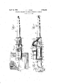
- FIG. 1 is a top plan view of an implement or machine embodying my invention
- Figure 2 is a transverse vertical sectional view taken on the line 2--2 of Figure 1, and
- Figure 3 is a sectional elevation of one of the nozzles.
- the implement comprises a reservoir or fountain A for containing the melted wax, said reservoir being shown as comprising a cylindrical tube 1 having caps 2 and 3 secured to opposite ends thereof with liquid tight joints.
- a filling opening l is provided at one side of the reservoir for receiving the lumps of wax to be melted or melted wax which may have been previously heated for example on a gas stove usual.
- One of the caps, in the present instance the cap 3 has an integral axial boss 5 upon which is fitted a heat insulated handle 6 formed of suitable material such as wood or fiber. Any suitable means may be provided for securing the handle to the boss, for example set screw 7.
- the other cap 2 has an outlet tube 8 projecting therefrom adjacent one side of the tube 1 in the outer end of which is removably fitted with a tapered friction engagement a nozzle or nib 9.
- Communication through the outlet tube Sand the interior of the reservoir is controlled by a frusto-conical valve head 10 formed with a stem 11 proj ecting outwardly through the reservoir and 7 having a pin and slot connection 12 with one end of a lever 13 pivotally mounted intermediate its ends at 14- and having a finger-piece 15 at its other end in convenient relation to the handle 6.
- the valve 10 is normally influenced into closed position by a compression spring 16, and may be opened by pressure of the finger of the operator on the finger piece 15. I j
- this coil consists of a helical winding 17 of high resistance wire upon a suitable rod 18 of insulating material such as glass.
- a suitable rod 18 of insulating material such as glass.
- one end of the rod 18 is .bent or offset as at 19 and fitted into the cap 3 so that the coil is located closely adjacent the bottom of the reservoir, that is the portion thereof nearest the outlet tube 8.
- This coill? is connected in an electric circuit by wardly into thehandle 6 and outwardly.
- the outer ends of the wires may be connected to a suitable known type of electric connector for connecting the wires to a source of electricity.
- the width or thickness of line D to be 'drawn maybe varied by changing the nozzle 9 for a larger nozzle 25 which projects into the outlet tube 8 farther than the nozzle 9. It takes longer for the wax to flow through the relatively longer passage in the nozzle 25, and as the nozzle is drawn over the silk at about the same speed for all operations, less wax will be supplied for any given time at the nozzle outlet of the nozzle 25 than at the outlet of the nozzle 9.
- Other nozzles of different length may be utilized for obtaining other variations in line thickness.
- the cap 3 is disconnected from the tube 1 so that when the cap 3is pulled away from the cylinder, the coil 17 being mounted on the cap is bodily withdrawn from the cylinder. Access to the valve may be had through the then open end of the tube.
- the wax will be maintained at a uniform temperature and consequently a uniform consistency, and will constantly freely flow by action of gravity through the nozzle 9 so that the operator may continuously perform without-any attention beinggiven to th'e'consistency or supply of the wax.
- the unyielding nib or nozzle 9 overcomes the difiiculties resulting from varying pressures upon the brushes now used, so that lines of uniform thickness may be drawn.
- the wax is such a thin liquid that several pieces of silk may be outlined at the same time by arranging the pieces in superposed relation on the frame E, the wax freely flowing through the several thicknesses whereby time and labor are saved.
- a brush as now used, only one thickness of silk being outlined at one time.
- thehand and arm of the operator are entirely free in all directions which great- 1y facilitates in the production of the artistic designs, especially those involving complex curves; and where it is desired to draw a perfectly strai ht line, a ruler may be used and the nozzle 9 moved along the edge of the ruler as is a pencil. This also is not possible with the brush now used.
- a machine of the character described comprising a substantially cylindrical reservoir to receive lumps of wax, a tubular coaxial heat insulating handle secured to one end thereof of a size and shape to be gripped like a fountain pen, an outlet nozzle projecting longitudinally from the other end adjacent one side thereof an electric heater within said reservoir for heating the contents thereof and disposed at one side of the reservoir adjacent said nozzle, and electrical wires connected to said heater and passing through said handle.
- a machine of the character described comprising a substantially cylindrical reservoir, a tubular coaxial heat-insulated handle secured to one end thereof and ofa size and shape to be gripped like a fountain pen, an outlet nozzle projecting longitudinally from the other end adjacent one side thereof, a valve for controlling communication between said nozzle and said reservoir, an electric heater within said reservoir for heating the contents thereof and disposed at one side of the reservoir adjacent said valve, means including a finger-piece adjacent said handle at the side of said reservoir opposite said nozzle outlet for actuating said valve, and elec trical wires connected to said heater and passing through said handle, whereby said machine can be held and manipulated like a fountain pen and said finger-piece can be operated by the index finger to control the valve.
Landscapes
- Special Spraying Apparatus (AREA)
Description
April 15, 1930. 1,754,330
OUTLININGIMPLEMENT FOB SURFACE ORNAMENTING PRQCESSES w Filed July 6, 1928 INVENTR Patented Apr. 15, 1930 Tr s FHQE
OUTLINING IMPLEMENT FOR SURFACE-ORNAMENTING PROCESSES Application filed July 6, 1928.
15 edreservoir for the wax and means communicating therewith for conducting the wax therefrom and applying it to the silk.
Further objects are to provide an implement of this character having novel and im- 20 proved features of construction whereby the reservoir and said means can be held in and manipulated by the hand of the operator; to provide such an implement wherein said means conducting and applying the wax is a nozzle or nib attached to said reservoir so that the melted WtlX may flow by gravity through said nozzle and spread thereby upon the silk; to provide an outlining implement of the character described including means for 30 regulating the flow of melted wax there from; to provide in such a device a plurality of nozzles whereby lines of different widths or thicknesses can be drawn; to provide a simple inexpensive and reliable construction,
will be brought out by the tion.
Referring to the accompanying drawing, in 4 which corresponding and like parts are designated throughout the several views by the same reference character. 7
Figure 1 is a top plan view of an implement or machine embodying my invention,
following desc i '45 for applying wax outlines to silk.
Figure 2 is a transverse vertical sectional view taken on the line 2--2 of Figure 1, and
Figure 3 is a sectional elevation of one of the nozzles.
50 Specifically describing the illustrated em- 5 and to obtain other advantages and results as j trlc heating 0011 B of any suitable construc- Seriel No. 290,861.
bodiment of the invention, the implement comprises a reservoir or fountain A for containing the melted wax, said reservoir being shown as comprising a cylindrical tube 1 having caps 2 and 3 secured to opposite ends thereof with liquid tight joints. A filling opening l is provided at one side of the reservoir for receiving the lumps of wax to be melted or melted wax which may have been previously heated for example on a gas stove usual. One of the caps, in the present instance the cap 3 has an integral axial boss 5 upon which is fitted a heat insulated handle 6 formed of suitable material such as wood or fiber. Any suitable means may be provided for securing the handle to the boss, for example set screw 7. The other cap 2 has an outlet tube 8 projecting therefrom adjacent one side of the tube 1 in the outer end of which is removably fitted with a tapered friction engagement a nozzle or nib 9. Communication through the outlet tube Sand the interior of the reservoir is controlled by a frusto-conical valve head 10 formed with a stem 11 proj ecting outwardly through the reservoir and 7 having a pin and slot connection 12 with one end of a lever 13 pivotally mounted intermediate its ends at 14- and having a finger-piece 15 at its other end in convenient relation to the handle 6. The valve 10 is normally influenced into closed position by a compression spring 16, and may be opened by pressure of the finger of the operator on the finger piece 15. I j
l fithin the reservoir A is arranged an election. As shown this coil consists of a helical winding 17 of high resistance wire upon a suitable rod 18 of insulating material such as glass. Preferably one end of the rod 18 is .bent or offset as at 19 and fitted into the cap 3 so that the coil is located closely adjacent the bottom of the reservoir, that is the portion thereof nearest the outlet tube 8. This coill? is connected in an electric circuit by wardly into thehandle 6 and outwardly.
through an axial opening 24: therein. The outer ends of the wires may be connected to a suitable known type of electric connector for connecting the wires to a source of electricity.
In operation of the implement, lumps of Wax are placed in the reservoir through the fillingopening 4 and the coil 17 is connected in an electric circuit. The heat from the coil quickly melts the lumps of wax into a thin liquid. Vhen the wax has been sufiiciently melted, the operator grasps the handle 6 in a manner similar to that in which a fountain pen is grasped, and opens the valve 10 by exerting pressure with the index linger on the finger-piece 15. The implement is sli htly atilted'andthe wax flows by gravity outwardly through the outlet tube 8 and the nozzle 9. The nozzle is applied to the silk C (Figure l) and drawn thereon in the desired direction according to the design to be produced so that thewax is spread upon the silk as indicated at J).
The width or thickness of line D to be 'drawn maybe varied by changing the nozzle 9 for a larger nozzle 25 which projects into the outlet tube 8 farther than the nozzle 9. It takes longer for the wax to flow through the relatively longer passage in the nozzle 25, and as the nozzle is drawn over the silk at about the same speed for all operations, less wax will be supplied for any given time at the nozzle outlet of the nozzle 25 than at the outlet of the nozzle 9. Other nozzles of different length may be utilized for obtaining other variations in line thickness.
Should it be desired to remove or repair the-coil 17 or the valve 10, the cap 3 is disconnected from the tube 1 so that when the cap 3is pulled away from the cylinder, the coil 17 being mounted on the cap is bodily withdrawn from the cylinder. Access to the valve may be had through the then open end of the tube.
With this construction it will be observed that the wax will be maintained at a uniform temperature and consequently a uniform consistency, and will constantly freely flow by action of gravity through the nozzle 9 so that the operator may continuously perform without-any attention beinggiven to th'e'consistency or supply of the wax. Furthermore the unyielding nib or nozzle 9 overcomes the difiiculties resulting from varying pressures upon the brushes now used, so that lines of uniform thickness may be drawn.
Another advantage of my device is that the wax is such a thin liquid that several pieces of silk may be outlined at the same time by arranging the pieces in superposed relation on the frame E, the wax freely flowing through the several thicknesses whereby time and labor are saved. This is not possible with a brush as now used, only one thickness of silk being outlined at one time. Alsothehand and arm of the operator are entirely free in all directions which great- 1y facilitates in the production of the artistic designs, especially those involving complex curves; and where it is desired to draw a perfectly strai ht line, a ruler may be used and the nozzle 9 moved along the edge of the ruler as is a pencil. This also is not possible with the brush now used.
It should be understood that the specific details of construction herein illustrated and described are primarily for the purpose of illustrating the principles of the invention, and that many modifications and changes may be made in said details without departing from the spirit or scope of the invention.
Having thus described my invention, what I claim is:
1. A machine of the character described comprising a substantially cylindrical reservoir to receive lumps of wax, a tubular coaxial heat insulating handle secured to one end thereof of a size and shape to be gripped like a fountain pen, an outlet nozzle projecting longitudinally from the other end adjacent one side thereof an electric heater within said reservoir for heating the contents thereof and disposed at one side of the reservoir adjacent said nozzle, and electrical wires connected to said heater and passing through said handle.
2. A machine of the character described comprising a substantially cylindrical reservoir, a tubular coaxial heat-insulated handle secured to one end thereof and ofa size and shape to be gripped like a fountain pen, an outlet nozzle projecting longitudinally from the other end adjacent one side thereof, a valve for controlling communication between said nozzle and said reservoir, an electric heater within said reservoir for heating the contents thereof and disposed at one side of the reservoir adjacent said valve, means including a finger-piece adjacent said handle at the side of said reservoir opposite said nozzle outlet for actuating said valve, and elec trical wires connected to said heater and passing through said handle, whereby said machine can be held and manipulated like a fountain pen and said finger-piece can be operated by the index finger to control the valve.
JOHN L. LITOMY.
Priority Applications (1)
| Application Number | Priority Date | Filing Date | Title |
|---|---|---|---|
| US290861A US1754330A (en) | 1928-07-06 | 1928-07-06 | Outlining implement for surface-ornamenting processes |
Applications Claiming Priority (1)
| Application Number | Priority Date | Filing Date | Title |
|---|---|---|---|
| US290861A US1754330A (en) | 1928-07-06 | 1928-07-06 | Outlining implement for surface-ornamenting processes |
Publications (1)
| Publication Number | Publication Date |
|---|---|
| US1754330A true US1754330A (en) | 1930-04-15 |
Family
ID=23117846
Family Applications (1)
| Application Number | Title | Priority Date | Filing Date |
|---|---|---|---|
| US290861A Expired - Lifetime US1754330A (en) | 1928-07-06 | 1928-07-06 | Outlining implement for surface-ornamenting processes |
Country Status (1)
| Country | Link |
|---|---|
| US (1) | US1754330A (en) |
Cited By (7)
| Publication number | Priority date | Publication date | Assignee | Title |
|---|---|---|---|---|
| US3711211A (en) * | 1971-02-01 | 1973-01-16 | Magic Circle Corp | Wax shaping tool |
| US3858985A (en) * | 1973-05-04 | 1975-01-07 | Daniel Enoch Fiveash | Hair removing applicator and process |
| US4052130A (en) * | 1975-12-01 | 1977-10-04 | Bruce Jan Forman | Wax application device |
| US4265618A (en) * | 1977-09-09 | 1981-05-05 | Solar Energy Technology, Inc. | Electrically heated endodontic syringe for injecting thermoplastic material into a root canal cavity |
| US4432715A (en) * | 1982-03-01 | 1984-02-21 | Ghim Duk K | Molten material dispensing apparatus |
| US5073696A (en) * | 1989-09-26 | 1991-12-17 | Kerr Manufacturing Company | Electrically heated wax shaping tool |
| USD325498S (en) | 1989-09-21 | 1992-04-21 | Kerr Manufacturing Company | Handpiece for wax shaping tool |
-
1928
- 1928-07-06 US US290861A patent/US1754330A/en not_active Expired - Lifetime
Cited By (7)
| Publication number | Priority date | Publication date | Assignee | Title |
|---|---|---|---|---|
| US3711211A (en) * | 1971-02-01 | 1973-01-16 | Magic Circle Corp | Wax shaping tool |
| US3858985A (en) * | 1973-05-04 | 1975-01-07 | Daniel Enoch Fiveash | Hair removing applicator and process |
| US4052130A (en) * | 1975-12-01 | 1977-10-04 | Bruce Jan Forman | Wax application device |
| US4265618A (en) * | 1977-09-09 | 1981-05-05 | Solar Energy Technology, Inc. | Electrically heated endodontic syringe for injecting thermoplastic material into a root canal cavity |
| US4432715A (en) * | 1982-03-01 | 1984-02-21 | Ghim Duk K | Molten material dispensing apparatus |
| USD325498S (en) | 1989-09-21 | 1992-04-21 | Kerr Manufacturing Company | Handpiece for wax shaping tool |
| US5073696A (en) * | 1989-09-26 | 1991-12-17 | Kerr Manufacturing Company | Electrically heated wax shaping tool |
Similar Documents
| Publication | Publication Date | Title |
|---|---|---|
| US1754330A (en) | Outlining implement for surface-ornamenting processes | |
| US2871587A (en) | Pressing iron | |
| US1619817A (en) | Wax-applying tool | |
| US1592148A (en) | Card-inscribing device | |
| US1769437A (en) | Electric waxing pencil | |
| US2214084A (en) | Cloth erasing tool | |
| US1815589A (en) | Batik wax lining tool | |
| GB985985A (en) | An implement for treating hair by the application of heat and vapour | |
| CN203623267U (en) | Batik painting pen | |
| US2151682A (en) | Fountain striping device | |
| US4009367A (en) | Steam-producing curling iron | |
| US1455842A (en) | Implement for writing | |
| US2248248A (en) | Bag sealing machine | |
| GB1430783A (en) | Steam iron | |
| CN203467882U (en) | Automatic hair curler | |
| US3864045A (en) | Waxing tool | |
| US1738916A (en) | Steam curling iron | |
| US1948605A (en) | Apparatus for producing closed ended tubes of celluloid or the like | |
| US2187670A (en) | Applicator | |
| US1457508A (en) | Fountain soldering tool | |
| US2175100A (en) | Soldering iron | |
| GB381351A (en) | Improvements in machines for treating floors | |
| US2482146A (en) | Batter dispensing cart for baking apparatus | |
| US1868416A (en) | Striping pencil | |
| US1911213A (en) | Sadiron |