US3751744A - Arrangement for tensioning the shank part of a shoe-upper - Google Patents
Arrangement for tensioning the shank part of a shoe-upper Download PDFInfo
- Publication number
- US3751744A US3751744A US00236869A US3751744DA US3751744A US 3751744 A US3751744 A US 3751744A US 00236869 A US00236869 A US 00236869A US 3751744D A US3751744D A US 3751744DA US 3751744 A US3751744 A US 3751744A
- Authority
- US
- United States
- Prior art keywords
- last
- shoe upper
- shoe
- bags
- arrangement
- Prior art date
- Legal status (The legal status is an assumption and is not a legal conclusion. Google has not performed a legal analysis and makes no representation as to the accuracy of the status listed.)
- Expired - Lifetime
Links
Images

Classifications
-
- A—HUMAN NECESSITIES
- A43—FOOTWEAR
- A43D—MACHINES, TOOLS, EQUIPMENT OR METHODS FOR MANUFACTURING OR REPAIRING FOOTWEAR
- A43D11/00—Machines for preliminary treatment or assembling of upper-parts, counters, or insoles on their lasts preparatory to the pulling-over or lasting operations; Applying or removing protective coverings
Definitions
- the invention relates to an arrangement for tensioning the shank part of a shoe upper, which has been already prior shaped, particularly for glued footwear.
- Tensioning elements are either finger-like wipers or spring loaded band wipers, or eventually elastic impermeable bags of a shape adjusted to the shank part of the shoe upper. They therefore take parts as a working element of the tensioning device in the working cycle of the machine and as they are in case of elastic impermeable bags adjusted in their shape to the shank of the tensioned footwear they do not stretch the shoe upper in its shank part, but solely develop a pressure thereon.
- Another drawback of this arrangement is a lack of operating space, particularly for machines where the toe cap and heel part are simultaneously tensioned.
- a substantial feature of this invention is the arrangement of the tensioning means of the shank part of the shoe upper on the mechanism serving for conveying the last with the lasted shoe upper to the working site, where the subsequent working operation on the footwear should be performed.
- Anotherfeature of this arrangement where for pressing the upper against the last elastic impermeable bags are used which can be filled with a pressure medium and which are provided at both sides of the space into which the last side with the lasted upper are introduced, is that the external walls of these elastic impermeable bags, distant from the space of the last with the lasted upper, are in contact with unyielding supports, whereas their walls facing the space with the last and extending with a stable upper and lower limitation the upper and lower circumference of the last plate after its introduction into this space, are free and when inoperative are beyond the circumference of this last, and in the course of filling of said elastic impermeable bags with a pressure medium their expansion in the longitudinal direction of the last being limited by stable rests, whereas in the lateral direction the expansion is limited in the upper part of the
- the arrangement according to this invention is furthermore provided with supports of these bags, having on their external walls eyelets support two arm levers, each of which has a replaceable rubber jaw on its upper arm for pressing the upper circumference of the shoe upper against the last and a planar surface on its lower arm which is in operating contact with a plunger of working cylinder of each of both supports, both working cylinders of these supports being slidable on a common guiding on the main supporting plate and each of them being connected with one of two pistons, provided oppositely in a common pressure cylinder fixed to the main supporting plate.
- the device for transfer of the last with the lasted upper to the working site where the subsequent operation on the worked footwear is performed consists of a swingable supporting arm bearing the main supporting plate with means for tensioning and pressing the shoe upper against the last, controlled by engagement of a toothed wheel on a supporting bolt of this supporting arm with a control rack slidable in a control guiding of a stand which stand can be displaced in a straight line between two positions along a track perpendicular to this control guiding, a vertical'cylindrical space being provided in the body of said control cam housing a piston damper connected with a common piston rod, with a tilting working piston engaging in a tilting working cylinder fixed to said common piston rod, the tilting working piston resting in the starting position of the supporting arm against the lower cover of the tilting working cylinder, the upper surface of the piston damper contacting the bottom of a vertical cylindrical space, the length of which is smaller than the operating track of the tilting working cylinder.
- Advantages which are offered by the arrangement according to this invention are that for tensioning of the shank part of the shoe upper 21 time interval is used, which is not part of the working cycle.
- the shoe upper is tensioned in its shank part after finished tensioning of the toe and heel part in the course of transport of the shoe upper on the last to the take off place.
- the elastic impermeable bags accordingto this invention enable a positive tensioning of the shank part ofthe shoe upper and not their sole pressing against the insole.
- the provisions of elastic impermeable bags as tensioning elements according to this invention enables the tensioning of the, whole footwear on a shoe upper conforming machine using glueing while leaving a suffient working space of the proper tensioning device of the toe and heel part.
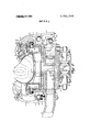
- FIG. 1 is an elevation of the arrangement in partia sectional view
- FIG. 2 a side view of the tensioning means with tensioning bags in partial sectional view.
- a transverse supporting carriage 3 of means for the transport of the last 74 with the lasted shoe upper 75 to the working site for perfonning the subsequent working operation is slidably supported by guiding ledges 2 fixed by screw bolts 201 to the working table 1.
- a rack 4 is provided on the supporting carriage 3, which is in constant engagement with a toothed driving wheel 5 firmly connected with a driven toothed wheel 6 engaging with a driving rack 7.
- This driving rack 7 is slidable on a working cylinder 8 and is linked by a cross-beam 10 with the piston rod 9.
- the piston rod 9 is fixed to the piston 11 and is guided slidingly in an opening of the lid 12 of the working cylinder 8, the working cylinder 8 with passages 801 and 802 for the pressure medium being suspended on a bolt 13 fixed on a bracked 14 fixed by screws 15 to the working table bracket
- a supporting bolt 16 is furthermore provided on the bracket 14 for rotatable supporting two firmly connected toothed wheels, namely the toothed driving wheel 5 and the toothed driven wheel 6.
- a stand 18 is supported slidably in a guiding 17 on the transverse supporting carriage 3. The movement is imparted to the stand 18 by a transverse motion screw 19.
- a vertical guiding 20 for a vertical working cylinder 21 having passages 211, 212 for the pressure medium with a vertical working piston 22 and a vertical piston rod 23 is provided on the stand 18.
- This vertical working piston rod 23 is firmly connected with a support plate 24 of a supporting arm 43 of the arrangement for tensioning the shank part of the shoe upper 75, the supporting plate 24 being slidable in the main guiding 25.
- a tilting working cylinder 27 having passages 271, 272 for the pressure medium with a lower lid 29, with a tilting working piston 28, a common piston rod 48 and an upper lid 30 with an opening is fixed on the supporting plate 24.
- the body of the vertical working cylinder 21 is provided with a thread for a motion screw 31 which is non rotatably connected with a toothed wheel 32 fixed on an auxiliary bolt 33 on the end of the vertical motion screw 31 if this auxiliary bolt 33 is rotatably arranged on the body of the stand 18.
- the toothed wheel 32 is in constant engagement with a pinion 36 fixed on a rotatable bolt 37 and can be adjusted by a manual knob 38.
- a forked bracket 39 for a suspension bolt 40 of both the supporting arm 43 and the toothed tilting wheel 41, fixed on the suspension bolt 40 by a feather key 42 is fixed on the upper end of the supporting plate 24.
- a control guiding 44 for the body of a control rack 45 which is in constant engagement with the toothed tilting wheel 41 is fixed on the forked bracket 39.
- a vertical cylindrical space 46 for a piston damper 47 connected with a common piston rod 48 is created within the body of the control cam 45.
- the cylindrical space 46 is at the top closed by a venting screw 49 and at the bottom, near the tilting working cylinder 27 closed by means of screws 51 by a lid 50 with an opening for the common piston rod 48.
- the main working plate 53 of the working site with a boss 54 and a sleeve 55 is rotatably supported by the stationary bolt 52.
- the boss 54 of the main working plate 53 is secured by a ring 521 with a safety screw 522.
- the plate 53 is urged by a torsion spring 56 against an adjustable stop with an extension 57 secured by a grooved screw 58.
- the arrangement for tensioning the shank part of the shoe upper 75 comprises a press cylinder 59 having a central passage 591 and two passages 592 and 593 at both ends of the cylinder for the pressure medium and two press pistons 60 actuated in opposite directions, with piston rods 61 passing through covers 62 fixed by screws 63.
- the cylinder 59 is fixed to the main supporting plate 53, and on guidings on this cylinder 59 parallel with its longitudinal axis two supporting cylinders 64 of elastic impermeable bags 66 are located slidably in opposite directions.
- the supporting cylinders 64 are controlled by means of cross-beams 67 fixed to the piston rods 61.
- Bag carriers are fixed to both supporting cylinders 64 by means of screws 68.
- the bag carriers 65 are furthermore provided with shields 69 of the elastic impermeable bags 66 having valves 661 fixed by nuts 663 with washers 662 to the bag carriers 65.
- the bag carriers 65 have in addition eyelets 70 for bolts 71 supporting oppositely arranged two arm pressure levers 73 transmitting pressure to the shoe upper 75 on the last 74.
- Safety rings 72 secure the position of both two arm pressure levers 73. Both these two arm pressure levers 73 have on their lower arms 732 planar surfaces 733 which are in constant engagement with plungers 76 of the supporting cylinders 64 by way of rollers 77 supported on bolts 78 fixed to the plungers 76.
- the plungers 76 are provided with channels 761 for passage of the pressure medium.
- the lower arm 732 of both two arm pressure levers 73 are urged against both rollers 77 by a helical pull spring 79, suspended on hanger pins 80, fixed on the lower arms 732 of both two arm pressure levers 73.
- the upper arms 931 of both two arm pressure levers 73 are provided with rubber jaws 81 vulcanized on inserts 82 engaging into dove tail grooves 83.
- the upper arms 731 of both two arm pressure levers 73 are provided with grooves 84 for locking levers 85, turning around pivots 86, fixed on the two arm pressure levers 73 and provided with washers 87 and safety rings 88.
- the locking levers are urged into grooves 89 of the inserts 82 by wire springs 90 situated in auxiliary grooves 91 of the locking levers 85, turning around the pivots 86 and resting with one end against the face of the auxiliary grooves 91 and with the other end against the face of grooves 84.
- a stationary rest plate 92 for the bags 66 is welded to the bottom part of one of both shields 69 in the space between both shields.
- the sequence of individual parts of the working cycle of the arrangement according to this invention can be chosen according to the machine, where the arrangement is applied. It can be for instance part of a glueing and tensioning machine tensioning simultaneously both the toe cap and the heel part.
- the task is to finish the shank part, to remove the footwear from the machine and pass it over for further operations of the technological cycle either to a take-01f platfonn or into a conveyor case.
- the arrangement according to this invention is brought below the last 74 with the shoe upper 75 tensioned in its toe and heel part, whereby the last 74 is maintained in the tensioning device by the holding frame 571.
- the movement is accomplished by shifting the piston 11 from the starting position by the action of the pressure medium introduced into the cylinder 12 over the passage 801 and released over passage 802.
- the driving rack 7 linked to the piston rod 9 of the piston 11 controls over both firmly connected toothed wheels, the driven wheel 6 and the driving wheel 5, the driven rack 4.
- the transverse supporting carriage 3 with the whole arrangement is thereby brought into its working position.
- the adjustment of the height is controlled by the vertical working piston 22 by admission of the pressure medium over passage 21 1 into the vertical working cylinder 21 below the piston 22.
- the fundamental adjustment of the piston of the vertical working cylinder 21 is accomplished by the motion screw 31 controlled by a manual knob 38 over a pinion 36 meshing with a toothed wheel 32, fixed to the motion screw 31.
- the adjustment of the resilient impermeable bags 66 in their proper working position with respect to the toe and heel part of the tensioned upper 75 is made by shifting the stand 18.
- the tensioning of the shoe upper 75 in its shank part proceeds as follows:
- the pressure medium entering over passages 592 and 593 shifts the press pistons 60 and the supporting cylinders 64 of the bag carriers 65 connected thereto toward the center of the press cylinder 59.
- the passages 591, 592, 593 are closed and the pressure medium in the spaces of the press cylinder 59 secures a constant position of the supporting cylinders 64 and thus also of the resilient impermeable bags 66.
- Pressure medium is thereafter introduced over channels 761 behind the faces of both plungers 76 which are forced out of their supporting cylinders 64, acting on the lower arms 732 of the two arm pressure levers 73 which press by means of the rubber jaws 81 the upper 75 with the last 74 against the shields 69.
- the channels 761 are thereafter closed and thus the position of the last 74 secured. Only now pressure medium is introduced over the valves 66] into the resilient impermeable bags 66, whichare from all sides surrounded by shields 69. They are now only able to extended in direction towards the.
- shoe upper 75 on the last 74 is thereby by means of these resilient impermeable bags 66 perfectly tensioned and pressed against the last 74.
- the pressure medium is finally released from the resilient impermeable bags: 66, the channels 761-of the plungers 76 are opened and by shifting the press pistons 60 into their starting position, th e last 74 with the tensioned shoe upper 75 is released and falls by gravity to the predetermined place.
- the supporting arm 43 with the tensioning device is now turned back by introduction of pressure medium over passage 272 above the tilting working piston 28.
- a shock free lowering of the tensioning device is again enabled by passage of the pressure medium in the vertical working space 46 over openings in the piston damper 47 to its other side.
- An arrangement for tensioning the shank part of a shoe upper held on a last in a shoe building machine comprising in combination:
- a stand supporting the last with the lasted shoe upper, menas for transferring said stand on a shoe upper conforming machine along a predetermined track, rigid supports for elastic impermeable bags provided on said stand at both lateral sides of said last with the lasted shoe upper,
- Arrangement as set forth in claim 1 comprising a supporting arm arranged vertically pivotably on said stand, a toothed tilting wheel on the near end of this arm,.a vertical tilting cylinder fixedto the stand, the piston rod of said cylinder extending into a rack engaging with said toothed tilting wheel, means for damping the movement of said arm, means determining the extreme positions of said rack, a main supporting plate supported by said supporting arm, a press cylinder with a couple of oppositely working press pistons with piston rods fixed to said main supporting plate, a couple of supporting cylinders slidably arranged on said main supporting plate, means for transmitting the movement of said piston rods of the press cylinder to said supporting cylinders, supports of elastic impermeable bags fixed to said supporting cylinders.
- said resilient means comprise elastic bags inflatable with a pressurized media to surround the elements of said shank parts to be glued.
Landscapes
- Footwear And Its Accessory, Manufacturing Method And Apparatuses (AREA)
- Sewing Machines And Sewing (AREA)
Applications Claiming Priority (1)
| Application Number | Priority Date | Filing Date | Title |
|---|---|---|---|
| CS2557A CS149840B1 (fr) | 1971-04-09 | 1971-04-09 |
Publications (1)
| Publication Number | Publication Date |
|---|---|
| US3751744A true US3751744A (en) | 1973-08-14 |
Family
ID=5363026
Family Applications (1)
| Application Number | Title | Priority Date | Filing Date |
|---|---|---|---|
| US00236869A Expired - Lifetime US3751744A (en) | 1971-04-09 | 1972-03-22 | Arrangement for tensioning the shank part of a shoe-upper |
Country Status (7)
| Country | Link |
|---|---|
| US (1) | US3751744A (fr) |
| BR (1) | BR7202063D0 (fr) |
| CS (1) | CS149840B1 (fr) |
| DE (1) | DE2264844A1 (fr) |
| FR (1) | FR2136304A5 (fr) |
| GB (1) | GB1382105A (fr) |
| IT (1) | IT951187B (fr) |
Cited By (4)
| Publication number | Priority date | Publication date | Assignee | Title |
|---|---|---|---|---|
| US3872531A (en) * | 1972-11-24 | 1975-03-25 | Eduardo Torrents | Device for continuous half-automatic production of cork soles for footwears |
| CN104669778A (zh) * | 2015-03-16 | 2015-06-03 | 董青山 | 一种气胀钳口绷网机 |
| CN108523314A (zh) * | 2018-05-29 | 2018-09-14 | 浙江柱达机械科技有限公司 | 中后帮弹性指压装置 |
| CN109793315A (zh) * | 2019-01-28 | 2019-05-24 | 东莞市意利自动化科技有限公司 | 一种用于中长靴制造的鞋楦夹具 |
Citations (4)
| Publication number | Priority date | Publication date | Assignee | Title |
|---|---|---|---|---|
| US1850151A (en) * | 1928-12-05 | 1932-03-22 | United Shoe Machinery Corp | Work-forwarding system |
| US3024480A (en) * | 1960-05-12 | 1962-03-13 | United Shoe Machinery Corp | Shoe handling devices |
| US3220033A (en) * | 1962-03-06 | 1965-11-30 | Morton S Bromfield | Apparatus for treating shoe uppers |
| US3594838A (en) * | 1970-05-28 | 1971-07-27 | Usm Corp | Lasting machines |
-
1971
- 1971-04-09 CS CS2557A patent/CS149840B1/cs unknown
-
1972
- 1972-02-17 DE DE2264844*A patent/DE2264844A1/de active Pending
- 1972-03-22 US US00236869A patent/US3751744A/en not_active Expired - Lifetime
- 1972-04-04 GB GB1551172A patent/GB1382105A/en not_active Expired
- 1972-04-07 BR BR2063/72A patent/BR7202063D0/pt unknown
- 1972-04-07 IT IT7222838A patent/IT951187B/it active
- 1972-04-10 FR FR7212535A patent/FR2136304A5/fr not_active Expired
Patent Citations (4)
| Publication number | Priority date | Publication date | Assignee | Title |
|---|---|---|---|---|
| US1850151A (en) * | 1928-12-05 | 1932-03-22 | United Shoe Machinery Corp | Work-forwarding system |
| US3024480A (en) * | 1960-05-12 | 1962-03-13 | United Shoe Machinery Corp | Shoe handling devices |
| US3220033A (en) * | 1962-03-06 | 1965-11-30 | Morton S Bromfield | Apparatus for treating shoe uppers |
| US3594838A (en) * | 1970-05-28 | 1971-07-27 | Usm Corp | Lasting machines |
Cited By (6)
| Publication number | Priority date | Publication date | Assignee | Title |
|---|---|---|---|---|
| US3872531A (en) * | 1972-11-24 | 1975-03-25 | Eduardo Torrents | Device for continuous half-automatic production of cork soles for footwears |
| CN104669778A (zh) * | 2015-03-16 | 2015-06-03 | 董青山 | 一种气胀钳口绷网机 |
| CN108523314A (zh) * | 2018-05-29 | 2018-09-14 | 浙江柱达机械科技有限公司 | 中后帮弹性指压装置 |
| CN108523314B (zh) * | 2018-05-29 | 2024-02-23 | 浙江柱达机械科技有限公司 | 中后帮弹性指压装置 |
| CN109793315A (zh) * | 2019-01-28 | 2019-05-24 | 东莞市意利自动化科技有限公司 | 一种用于中长靴制造的鞋楦夹具 |
| CN109793315B (zh) * | 2019-01-28 | 2023-07-21 | 广东意华鞋业科技研究院有限公司 | 一种用于中长靴制造的鞋楦夹具 |
Also Published As
| Publication number | Publication date |
|---|---|
| BR7202063D0 (pt) | 1973-06-07 |
| CS149840B1 (fr) | 1973-08-23 |
| IT951187B (it) | 1973-06-30 |
| FR2136304A5 (fr) | 1972-12-22 |
| GB1382105A (en) | 1975-01-29 |
| DE2264844A1 (de) | 1975-05-15 |
| DE2207316A1 (de) | 1972-10-19 |
| DE2207316B2 (de) | 1975-07-17 |
Similar Documents
| Publication | Publication Date | Title |
|---|---|---|
| US3751744A (en) | Arrangement for tensioning the shank part of a shoe-upper | |
| US3138810A (en) | Heel end assembling and back part molding machines | |
| US3284558A (en) | Injection molding composite bottoms | |
| US3849818A (en) | Adhesive control for shoe lasting machine | |
| US2423878A (en) | Shoe pressing apparatus | |
| US3000024A (en) | Shoe machine | |
| US2770822A (en) | Sole attaching machine | |
| US2201996A (en) | Sole laying machine | |
| US2828496A (en) | Sole pressing machine | |
| US2274063A (en) | Shoe-shaping machine | |
| US3523317A (en) | Heel and toe lasting apparatus | |
| US2059831A (en) | Shoe press | |
| US2265398A (en) | Method of and apparatus for making shoes | |
| US2558847A (en) | Machine for applying pressure to shoe bottoms | |
| US2694821A (en) | Machine for shaping shoe uppers | |
| US2594728A (en) | Shoe sole press | |
| US2050377A (en) | Machine for shaping uppers over lasts | |
| US2254369A (en) | Machine for shaping uppers over lasts | |
| US2787799A (en) | Fluid-pressure sole press | |
| US2679059A (en) | Shoe-sole laying press | |
| US2083777A (en) | Machine for applying pressure to shoe bottoms | |
| US2124654A (en) | Machine and method for applying pressure to shoe bottoms | |
| GB1275287A (en) | Apparatus for roughing the overlasted portions of the bottoms of shoe uppers | |
| US3102281A (en) | Wrapper-attaching machine for shoe manufacture | |
| US2720666A (en) | Pressure applying apparatus |