US3720875A - Differential encoding with lookahead feature - Google Patents
Differential encoding with lookahead feature Download PDFInfo
- Publication number
- US3720875A US3720875A US00195398A US3720875DA US3720875A US 3720875 A US3720875 A US 3720875A US 00195398 A US00195398 A US 00195398A US 3720875D A US3720875D A US 3720875DA US 3720875 A US3720875 A US 3720875A
- Authority
- US
- United States
- Prior art keywords
- sequence
- code
- value
- input
- pattern
- Prior art date
- Legal status (The legal status is an assumption and is not a legal conclusion. Google has not performed a legal analysis and makes no representation as to the accuracy of the status listed.)
- Expired - Lifetime
Links
- 238000000034 method Methods 0.000 claims abstract description 32
- 230000008569 process Effects 0.000 claims abstract description 16
- 230000004044 response Effects 0.000 claims description 25
- 238000005070 sampling Methods 0.000 claims description 13
- 238000005056 compaction Methods 0.000 claims description 4
- FGUUSXIOTUKUDN-IBGZPJMESA-N C1(=CC=CC=C1)N1C2=C(NC([C@H](C1)NC=1OC(=NN=1)C1=CC=CC=C1)=O)C=CC=C2 Chemical compound C1(=CC=CC=C1)N1C2=C(NC([C@H](C1)NC=1OC(=NN=1)C1=CC=CC=C1)=O)C=CC=C2 FGUUSXIOTUKUDN-IBGZPJMESA-N 0.000 claims 2
- 230000007704 transition Effects 0.000 abstract description 16
- 230000010363 phase shift Effects 0.000 abstract description 5
- 230000001447 compensatory effect Effects 0.000 abstract description 2
- 238000012360 testing method Methods 0.000 description 16
- 210000004027 cell Anatomy 0.000 description 6
- 230000008859 change Effects 0.000 description 6
- 230000003466 anti-cipated effect Effects 0.000 description 3
- 238000010586 diagram Methods 0.000 description 3
- 230000000694 effects Effects 0.000 description 3
- 238000012545 processing Methods 0.000 description 3
- 238000009825 accumulation Methods 0.000 description 2
- 230000009471 action Effects 0.000 description 2
- 238000013459 approach Methods 0.000 description 2
- 230000008901 benefit Effects 0.000 description 2
- 230000005540 biological transmission Effects 0.000 description 2
- 230000003190 augmentative effect Effects 0.000 description 1
- 238000006243 chemical reaction Methods 0.000 description 1
- 238000007796 conventional method Methods 0.000 description 1
- 230000003247 decreasing effect Effects 0.000 description 1
- 230000001934 delay Effects 0.000 description 1
- 230000003111 delayed effect Effects 0.000 description 1
- 230000036039 immunity Effects 0.000 description 1
- 230000010365 information processing Effects 0.000 description 1
- 230000000630 rising effect Effects 0.000 description 1
- 230000035945 sensitivity Effects 0.000 description 1
- 210000000352 storage cell Anatomy 0.000 description 1
Images


Classifications
-
- H—ELECTRICITY
- H03—ELECTRONIC CIRCUITRY
- H03M—CODING; DECODING; CODE CONVERSION IN GENERAL
- H03M7/00—Conversion of a code where information is represented by a given sequence or number of digits to a code where the same, similar or subset of information is represented by a different sequence or number of digits
- H03M7/30—Compression; Expansion; Suppression of unnecessary data, e.g. redundancy reduction
- H03M7/3002—Conversion to or from differential modulation
- H03M7/3048—Conversion to or from one-bit differential modulation only, e.g. delta modulation [DM]
- H03M7/3051—Conversion to or from one-bit differential modulation only, e.g. delta modulation [DM] adaptive, e.g. adaptive delta modulation [ADM]
-
- B—PERFORMING OPERATIONS; TRANSPORTING
- B65—CONVEYING; PACKING; STORING; HANDLING THIN OR FILAMENTARY MATERIAL
- B65G—TRANSPORT OR STORAGE DEVICES, e.g. CONVEYORS FOR LOADING OR TIPPING, SHOP CONVEYOR SYSTEMS OR PNEUMATIC TUBE CONVEYORS
- B65G60/00—Simultaneously or alternatively stacking and de-stacking of articles
Definitions
- ABSTRACT Analog input information is compacted by a differential encoding process that anticipates abrupt transitions in signal levels and initiates compensatory action in time to prevent the encoded representations of such transitions from being shifted out of phase due to slope overload.
- Digitized analog signal representations which are to be encoded are first passed through a shift register having L stages, the number L signifying the amount of lookahead, i.e., the number of sampled analog elements that are to be analyzed as a group prior to encoding.
- the contents of the shift register at any instant will furnish the history of variations in the respective levels of the first L signal elements which currently await encoding.
- the system is able to select an optimal encoded bit pattern which would most nearly represent in compact digital code form the apparent trend of these variations, and the leading bit or bits of this pattern will be fed out by the encoder.
- the optimal bit pattern is continually updated as the makeup of the lookahead code group changes. By anticipating rapid changes of level, the phase shift of elements having highly contrasting levels is avoided.
- images When images are converted into digitized form for transmission or storage purposes, their picture elements are represented at one stage or another by a coding notation which requires a relatively large number of bits per picture element.
- Eight bits (one byte), for example, may be used to represent various shades or grey levels on a scale of values from to 255, where the extreme values represent black and white (or vice versa), and the intermediate values represent intervening levels or shades of grey.
- adifferential encoding process such as delta modulation (AM) or differential pulse code modulation (DPCM); whereby the code for each picture element represents not the absolute grey level of that element but merely an approximate incremental difference between the grey level of the current picture element and the encoded greylevel representation of the element which immediately preceded it.
- a delta-modulation encoding scheme which utilizes only one bit per picture element, for example, a 0 bit may represent a transition to a darker shade, while a I bit may represent a transition to a lighter shade.
- Adjoining picture elements which are at approximately the same grey level may be represented by a string of alternate ls and Os denoting a steadystate condition.
- An object of the present invention is to improve the fidelity with which signals representing analog phenomena may be processed at high speed by differential encoding methods, and particularly to prevent phase shift due to slope overload where the analog signal being processed has many abrupt transitions between widely differing levels.
- lookahead encoding which enables rapid changes in the levels of adjoining signal elements to be anticipated in the coding more promptly than would otherwise be the case.
- a series of picture element representations is temporarily stored and analyzed for trends in grey level variations before being encoded by the delta modulation or other differential encoding process. Abrupt changes will be detected long before they are encoded, and the coding that represents such changes will be initiated in sufficient time so that it will be accurately placed in the encoded sequence, notwithstanding the slope constraints imposed by the response time of the encoding apparatus. This may cause some initial inaccuracy as the system starts to respond early to the anticipated change, but phase shifts at the extreme peak and valley points in the response waveform will be avoided, so that the overall accuracy is greatly improved.
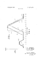
- FIG. 1 is a set of time-based graphs depicting the approximate manner in which a differential encoding system may respond to a given input signal representation, with and without the lookahead encoding feature of the present invention.
- FIG. 2 is a simple block diagram of a conversion system for differentially encoding and decoding data.
- FIG. 3 is a general block diagram of an illustrative differential encoder which embodies the lookahead feature of this invention.
- FIG. 4 is a more detailed schematic showing of the encoder represented in FIG. 3, assuming the number of lookahead stages (L) to be 3.
- the multibit grey level codes V are converted by encoder to differential codes N which, in some systems, may have only a single bit per code word.
- the image data may be highly compacted for efficient transmission or highdensity storage.
- the differential codes N are converted by a decoder 32 to multibit absolute codes A.
- the final codes A may or may not conform closely to the corresponding original codes V. (The word code is here used in the sense of a code symbol or coded representation.)
- FIG. 1 represents in greatly simplified form a typical sequence of events that may occur in the course of such an encoding operation.
- sampling times 1, 2, 3, etc. correspond respectively to various instants when the grey-level analog signal generated by the image scanning device is sampled and encoded into absolute codes to represent the shades or grey levels of discrete picture elements.
- the graph or curve 21 is a plot of the variations in shade or grey level of a series of these scanned picture elements.
- the graph 22 depicts the response of the encoding-decoding system, as represented by the decoded output A, FIG. 2, when the differential encoder does not have a lookahead feature.
- Graph 23 FIG.
- the differentially encoded signal will consist of alternating positive and negative pulses (FIG. 1). These cancel each other out in net effect, but they also produce what is known as granular noise.
- a slanted line having an angle of slope B represents the most rapid response that the differential encoding-decoding system can make to a transition between significantly different grey levels in succeeding picture elements.
- the encoder will be able to follow the transition accurately.
- the response of the conventional encoder will fall behind the true image representation (as illustrated by the behavior of the response characteristic 22, FIG. 1, between the sampling times 40 and 60), since it is limited to the maximum slope angle B which is con- I siderably less than the slope of the true image graph 21 between the sampling points 40 and 45.
- the conventional encoding technique will distort the image so that when it is reproduced, the picture elements that should have occurred at the peaked portion of graph 21, between points 45 and 60 of the sampling sequence, FIG. 1, will have no counterparts in graph 22, and the peak of graph 22 (which is of less amplitude than the peak' of 21) is shifted in phase relative thereto.
- the peak of graph 22 which is of less amplitude than the peak' of 21
- severe distortions of the image representation are apt to occur in the conventional differential encoding process.
- the maximum slope angle B of the response characteristic There are practical reasons for limiting the maximum slope angle B of the response characteristic. First, if the minimum increment by which the differentially e'ncoded signal level may change were made too large, this would increase the above-described granular noise which is. generated during steady-state intervals. Moreover, if this slope angle should approach too closely, the system then would become'unduly sensitive to extraneous noise pulses. A certain degree of noise immunity is needed, and to achieve this, the maximum slope angle B must be limited to a value substantially less than 90, even though this results in the condition known as slope overload in high-contrast regions. The purpose of the present invention is to permit slope overloading to occur while minimizing its undesirable effects.
- FIG. 3 is a functional representation of a differential encoder which is provided with a lookahead feature in accordance with the principle of the invention. Included in this encoder is a delay unit 40 comprising, for example, a shift register having L stages, where L is the number of picture-element code symbols contained in the lookahead sequence, i.e., the number of absolutevalue code words in the V series (FIG. 2) which will be analyzed to determine the differential encoding of the picture element currently under consideration.
- L is the number of picture-element code symbols contained in the lookahead sequence, i.e., the number of absolutevalue code words in the V series (FIG. 2) which will be analyzed to determine the differential encoding of the picture element currently under consideration.
- the subscript k will represent any integer from 1 to the total number of picture elements in the image being processed.
- a sequence of input code words V 1 equal in number to L is assembled in the shift register 40.
- the pattern of grey level variations represented by this sequence is analyzed by a pattern selector 42 to select a pattern of differential codes N N N 1 which, if decoded would yield a series of code words A A .AHL that conforms in optimum fashion to the lookahead code sequence currently stored in the delay unit 40.
- the first value N, in this series of values N N is read out as the code symbol for the current input code' V (i.e., the code symbol representing the grey level of the current picture element).
- register 40 The contents of register 40 then are shifted by one stage, a new input code word is entered into the V position of this register, and a new pattern of N codes is selected by the unit 42 to give the optimum representation of the lookahead sequence in differentially encoded form.
- This continual updating and analysis of the set of code words in the lookahead sequence insures that any sudden changes in shade will be detected soon enough to start a corresponding trend in the differentially encoded output, so that the high-contrast areas of the image are notunduly distorted.
- the pattern selector 42 operates in a manner such as to satisfy some definite performance criterion which has been specified.
- a number of different code patterns N Nk+L- must be tested for optimum response.
- L 3 and that the register 40 stores a series of codes V,, V, and V each containing, say, eight bits.
- each of the differential codes N N and N contains a single bit, 1 or 0, with l representing an upward step in a delta modulation type of encoding process, and 0 representing a downward step in that process.
- there will be eight possible bit patterns or sets of binary code words that must be considered by the pattern selector 42 namely:
- the pattern selector 42 now proceeds to apply some specified performance criterion to these various bit patterns in order to select the one which, when decoded, would yield a response that corresponds in optimum fashion to the history of the shading variations represented by the lookahead code sequence V V and V (or in general, V V currently stored in register 40. To do this, the selector 42 considers each bit pattern in turn, and it passes the bits of each pattern through a decoder 44 which performs the same function as decoder 32, FIG. 2, yielding an output code A,, having the same format as the input code V but not necessarily identical in value thereto. The selector 42 then computes a specified function of V,, Vkflr1 and A,, A which measures the performance that the system would exhibit if the current test pattern or test sequence N N N;, were chosen as the optimum encoded sequence. I
- Performance criteria other than the one specified above may be chosen if desired. The choice may depend upon the type of image data being processed (textual information as compared with pictures, for example). In the specific embodiment described hereafter, the minimum value of the function given above will be taken as the performance criterion.
- FIG. 4 there is shown a schematic layout of a differential encoder for performing the functions attributed to the units 40, 42 and 44 shown in FIG. 3.
- the shift register or delay unit 40 and the decoder 44 of FIG. 3, are identified by like reference numbers in FIG. 4.
- the shift register 40 has three stages which respectively store the absolute video input codes V V and V k being any integer from I to the total number of picture elements to be differentially encoded. Actually, only one bit-storing position of each register stage is shown in FIG. 4. Since each of the V codes is assumed, in the present embodiment, to constitute a multibit word, there will be as many bit storage cells per stage as there are bits per V code word. Thus, if the absolute grey-level value is represented by an eight-bit code, then each register stage such as V,,, for example, actually would consist of eight cells with parallel-bit inputs. For simplicity, however, the register 40 is shown in FIG. 4 as having only one bit-storage cell per stage. (The same convention is adopted for some of the other registers shown in FIG. 4, to be identified hereinafter.) The purpose of the cells marked V*,,.,, and V*,,.,; will be explained presently.
- the master clock 46 emits a sequence of timing pulses numbered from 1 through 14. These should not be confused with the sampling times I, 2, 3, etc., FIG. 1.
- the entire series of master clock pulses must be generated as many times as needed between each successive pair of sampling times (or in other words, between two successive entries of video codes into the shift register 40) in order to perform the required bit pattern tests.
- the performance criterion P which is used in this example will be the minimum valueof the function:
- the &" symbol is used in FIG. 4 to represent an AND circuit.
- the arithmetic unit 54 is adapted to perform an operation involving the calculation and accumulation of successive (V-A) values for each N bit pattern being tested.
- the comparator 56 compares the output value P furnished by the arithmetic unit 54 with a value P* stored in a multibit register 58 (of which only one bit-storage cell is shown), P* being the maximum value of P which is considered acceptable in the present state of the computations. If P is less than P, then the current value of P is substituted for the current value of I".
- Register 60 is a single-bit storage device for storing a bit having the value N*,,, which is tentatively the value of the encoded bit, subject to possible change if a different bit pattern is chosen before the encoded bit is read out.
- the master clock 46 emits its timing pulses in the numerical order indicated. Each timing pulse initiates a particular step of the operation, as will be described below.
- shift register 40 will be storing the three video (V) input codes which form the current lookahead sequence.
- Counter 50 stands at 000 to represent the first of the N bit patterns to be tested.
- Re-. gister 52 is storing the value A which is the absolute code corresponding to the encoded bit N,,., that most recently was generated by the encoder.
- the remaining A codes stored in register 52 are of only academic interest at this time.
- the initial value of P* in register 58 will have been set to the maximum possible value that P may have.
- the sequence of 14 steps described below will be performed eight times for each code bit that is fed out of the encoder. This involves setting up eight different sets of absolute codes A,,, A A to correspond with the differentially decoded equivalents of the eight different N-bit patterns, and performing eight calculations of the function P which is to be optimized. If the number of codes in the lookahead sequence (L) is changed, then a different number of calculations will be performed for each encoded bit fed out, and the number of clock pulses will be different.
- the encoding apparatus shown in FIG. 4 is designed specifically for a lookahead value L 3, and it assumes a simple deltamodulation type of encoding process for illustrative purposes.
- N the first bit of the test pattern now stored in counter 50
- A the absolute code corresponding to the last differentially encoded bit N that was fed out of the encoder
- Decoder M is enabled to calculate a new absolute code A using the former code A,, and the tentative value of the bit N,, in the current test pattern.
- the code A and the second bit N of the current test pattern are entered into decoder 44.
- the code A, and the first video input code V in the lookahead sequence are entered into the arithmetic unit 54.
- the decoder 44 is enabled to calculate a new code 7 A based upon the bit N of the current test pattern and the previously calculated value of A
- the arithmetic unit 54 is enabled to calculate P (A V,,) which is the first term in the summation of the function defined hereinabove. These P values will be accumulated by the arithmetic unit 54 until execution of the function is completed.
- the code A and the third bit N of the current test pattern are entered into decoder 44.
- the code A and the second input code V of the current lookahead series are entered into the arithmetic unit 54.
- the decoder 44 is enabled to calculate a new code A using as inputs the bit N of the test pattern and the previously calculated value of A
- the arithmetic unit 54 is enabled to calculate a new value of P consisting of the previously calculated P value now augmented y k+1"' in- 9.
- the code A calculated by decoder 44 is entered into the register 52. I
- the arithmetic unit 54 is enabled to calculate the value P P V A This completes the accumulation of the intermediate P values to give the final P value.
- the comparator 5a is enabled to compare the value of P calculated by the arithmetic unit 54 with the value P currently stored in register 58.
- the P* value in register 58 is set equal to the P value calculated by the arithmetic unit. This recognizes that the new P value more closely approaches the minimum value which corresponds to optimum performance of the lookahead encoder, under the presently assumed conditions.
- N is set equal to N, in register 50.
- A, in register 52 is set equal to A,, in the same register. if the current A code represents the optimum choice, then it must be saved for use in encoding the next input video code.
- the setting of the counter 50 is incremented by l to create a new bit pattern for testing. If counter 50 does not overflow, this means that the available bit patterns have not yet been exhausted. Under this condition, steps 1 to 14 merely are repeated, and no code bit is fed out. (The encoded N bit is not fed out until all of the available N-bit patterns have been tested.) If the incrementing of counter 50 causes it to overflow (i.e., go from a setting of 111 to 000, in this instance), this means that the last bit pattern in the series has been tested. In that event, the following actions take place concurrently:
- the V value in shift register 40 is set equal to the next input video code from the scanning digitizer.
- the former V value i.e., the present Vfi value
- the former V value i.e., the present V* value
- a synch pulse is sent back to the image scanning digitizer to make a new video input code available for use at the proper time.
- the P value stored in register 58 is set to have the maximum possible value which P may have.
- Steps l-l4 described above are repeated without interruption while the encoder is operating.
- Special-purpose encoding hardware such as that shown in FIG. 4 enables the testing of the various N-bit patterns to take place very rapidly, and high encoding accuracy can be achieved with only a moderate sacrifice of the encoding rate, as compared with the conventional type of differential encoding without the lookahead feature, which is a little more rapid but much less accurate.
- the invention is not limited to special hardware implementations, however, and can readily be carried out by programming a general-purpose computer to perform operations which are analogous to those just described.
- L The effect ofincreasing L is to increase the encoding accuracy while decreasing the speed. In most situations it is found that very little additional accuracy is gained by increasing L beyond a certain small value (e.g., 4). Hence, for practical purposes, the encoding rate can be kept reasonably high without appreciably sacrificing the high accuracy that lookahead encoding is capable of providing.
- the video (V) input may be kept in analog form, and the computation of P may be performed by an analog calculator with A codes being converted to analog form for input to the calculator, if this mode of operation is found more convenient.
- V and A code sequences may be used for measuring the correlation between V and A code sequences.
- One such criterion has been given as an example.
- Another (which perhaps is more likely to be used in practice) would be the minimum of the accumulated absolute values of the differences V, A where i varies from k to k+L-l for each of the test code patterns.
- a lookahead encoding method which comprises the steps of:
- step c calculating the value of a performance function that measures the correlation between such output value sequence and the current input value sequence
- step d is the summation of values (V, A,) where V represents an input value to be encoded, A represents a decoded output value, as calculated by step c, i is an integer whose value ranges from k (the serial number of the leading input value currently stored in said delay means) to k+L+, and L is the number of input values stored in said delay means, and step e involves selecting the code pattern which yields a performance function of minimum value for a given value of k.
- Apparatus for encoding absolute input values of a sampled analog signal into digitized code symbols that represent the variations of such input values with respect to each other comprising:
- delay means for temporarily storing a sequence of input values attained by the sampled analog signal
- digital code pattern generating means for making a series of code patterns successively available, each such pattern representing a possible sequence of code symbols tentatively representing in differentially encoded form the variations of said temporarily stored sequence of input values
- differential decoding means operable in response to each of said code patterns as it becomes available to generate the sequence of output value representations which would be produced by such a code pattern in the event it were selected to represent the sequence of input values currently stored in said delay means;
- calculating means responsive to each sequence of output value representations generated by said decoding means to calculate the value of a performance function that measures the correlation between such output value sequence and the current input value Sequence;
- output means utilizing said stored code pattern portion as a differentially encoded representation of a corresponding portion of said input value sequence.
- the performance function calculated by calculating means d is the summation of values (V, AM, where V represents an input value to be encoded, A represents a calculated output value, 1' is an integer whose value ranges from k (the serial number of the leading input value currently stored in delay means a) to k+L-l-, where is the number of input values stored in said delay means, and comparing means e determines which of said code patterns has the performance function of minimum value.
- a differential encoding apparatus of the delta modulation type comprising:
- a shift register for storing a sequence of input code symbols representing sampled analog signal amplitudes
- a binary counter operable to generate a series of bit patterns, each such pattern representing a possible sequence of signal amplitude changes which could represent said sampled analog signal amplitudes in differentially encoded form;
- differential decoding means operable in response to each of said bit patterns as it becomes available to generate the sequence of output code symbols which would be produced by such a bit pattern if it were to serve as the differentially encoded representation of said input code symbol sequence;
- calculating means responsive to each sequence of output code symbols generated by said decoding means for calculating the value of a performance function that measures the correlation between the respective input and output code symbol sequences;
- comparing means for determining which of the output means utilizing the leading bit of said optimum bit pattern to furnish an output signal representing in differentially encoded form the leading input signal amplitude stored in said shift register.
Landscapes
- Engineering & Computer Science (AREA)
- Theoretical Computer Science (AREA)
- Compression, Expansion, Code Conversion, And Decoders (AREA)
- Transmission Systems Not Characterized By The Medium Used For Transmission (AREA)
- Image Input (AREA)
Applications Claiming Priority (1)
| Application Number | Priority Date | Filing Date | Title |
|---|---|---|---|
| US19539871A | 1971-11-03 | 1971-11-03 |
Publications (1)
| Publication Number | Publication Date |
|---|---|
| US3720875A true US3720875A (en) | 1973-03-13 |
Family
ID=22721271
Family Applications (1)
| Application Number | Title | Priority Date | Filing Date |
|---|---|---|---|
| US00195398A Expired - Lifetime US3720875A (en) | 1971-11-03 | 1971-11-03 | Differential encoding with lookahead feature |
Country Status (7)
| Country | Link |
|---|---|
| US (1) | US3720875A (enExample) |
| JP (1) | JPS528141B2 (enExample) |
| CA (1) | CA1017865A (enExample) |
| DE (1) | DE2253064A1 (enExample) |
| FR (1) | FR2158231A1 (enExample) |
| GB (1) | GB1342447A (enExample) |
| IT (1) | IT967903B (enExample) |
Cited By (5)
| Publication number | Priority date | Publication date | Assignee | Title |
|---|---|---|---|---|
| US3806918A (en) * | 1973-03-26 | 1974-04-23 | Recognition Equipment Inc | Digital phase lock loop |
| US3829779A (en) * | 1972-02-04 | 1974-08-13 | Nippon Electric Co | Multilevel code transmission system |
| US4039948A (en) * | 1974-06-19 | 1977-08-02 | Boxall Frank S | Multi-channel differential pulse code modulation system |
| US4051470A (en) * | 1975-05-27 | 1977-09-27 | International Business Machines Corporation | Process for block quantizing an electrical signal and device for implementing said process |
| EP0198924A4 (en) * | 1984-05-22 | 1989-01-19 | Advance Kaihatsu Kenkyusho | SIGNAL PROCESSING SYSTEM. |
Families Citing this family (3)
| Publication number | Priority date | Publication date | Assignee | Title |
|---|---|---|---|---|
| JPS55129346U (enExample) * | 1979-03-09 | 1980-09-12 | ||
| FR2543380B1 (fr) * | 1983-03-24 | 1985-07-26 | Labo Cent Telecommunicat | Procede et dispositif de transcodage d'un signal numerique mic et application au codage analogique-numerique d'un signal analogique a large bande |
| DE3404828C2 (de) * | 1984-02-09 | 1986-07-24 | Berolina Elektronik Beratungs- und Vertriebs GmbH, 1000 Berlin | Verfahren zur Kompression der die Grauwertstufen repräsentierenden Information eines digital zu übertragenen Bildsignals |
Citations (3)
| Publication number | Priority date | Publication date | Assignee | Title |
|---|---|---|---|---|
| US3394352A (en) * | 1965-07-22 | 1968-07-23 | Electronic Image Systems Corp | Method of and apparatus for code communication |
| US3596267A (en) * | 1969-01-28 | 1971-07-27 | Bell Telephone Labor Inc | Digital code converter for converting a delta modulation code to a different permutation code |
| US3601702A (en) * | 1969-03-17 | 1971-08-24 | Gte Automatic Electric Lab Inc | High speed data transmission system utilizing nonbinary correlative techniques |
-
1971
- 1971-11-03 US US00195398A patent/US3720875A/en not_active Expired - Lifetime
-
1972
- 1972-09-05 GB GB4108072A patent/GB1342447A/en not_active Expired
- 1972-09-27 IT IT29722/72A patent/IT967903B/it active
- 1972-10-06 JP JP47099976A patent/JPS528141B2/ja not_active Expired
- 1972-10-11 FR FR7236798A patent/FR2158231A1/fr not_active Withdrawn
- 1972-10-28 DE DE2253064A patent/DE2253064A1/de active Pending
- 1972-11-01 CA CA155,566A patent/CA1017865A/en not_active Expired
Patent Citations (3)
| Publication number | Priority date | Publication date | Assignee | Title |
|---|---|---|---|---|
| US3394352A (en) * | 1965-07-22 | 1968-07-23 | Electronic Image Systems Corp | Method of and apparatus for code communication |
| US3596267A (en) * | 1969-01-28 | 1971-07-27 | Bell Telephone Labor Inc | Digital code converter for converting a delta modulation code to a different permutation code |
| US3601702A (en) * | 1969-03-17 | 1971-08-24 | Gte Automatic Electric Lab Inc | High speed data transmission system utilizing nonbinary correlative techniques |
Cited By (5)
| Publication number | Priority date | Publication date | Assignee | Title |
|---|---|---|---|---|
| US3829779A (en) * | 1972-02-04 | 1974-08-13 | Nippon Electric Co | Multilevel code transmission system |
| US3806918A (en) * | 1973-03-26 | 1974-04-23 | Recognition Equipment Inc | Digital phase lock loop |
| US4039948A (en) * | 1974-06-19 | 1977-08-02 | Boxall Frank S | Multi-channel differential pulse code modulation system |
| US4051470A (en) * | 1975-05-27 | 1977-09-27 | International Business Machines Corporation | Process for block quantizing an electrical signal and device for implementing said process |
| EP0198924A4 (en) * | 1984-05-22 | 1989-01-19 | Advance Kaihatsu Kenkyusho | SIGNAL PROCESSING SYSTEM. |
Also Published As
| Publication number | Publication date |
|---|---|
| DE2253064A1 (de) | 1973-05-10 |
| FR2158231A1 (enExample) | 1973-06-15 |
| CA1017865A (en) | 1977-09-20 |
| JPS528141B2 (enExample) | 1977-03-07 |
| GB1342447A (en) | 1974-01-03 |
| IT967903B (it) | 1974-03-11 |
| JPS4854856A (enExample) | 1973-08-01 |
Similar Documents
| Publication | Publication Date | Title |
|---|---|---|
| US4216460A (en) | Transmission and/or recording of digital signals | |
| KR0161511B1 (ko) | 데이타 워드 송신장치 및 수신장치 | |
| EP0199088B1 (en) | Method and apparatus for modifying a run-length limited code | |
| JPS6346611B2 (enExample) | ||
| US3720875A (en) | Differential encoding with lookahead feature | |
| US3727037A (en) | Variable increment digital function generator | |
| US7069481B2 (en) | Data recovery circuit for minimizing power consumption by non-integer times oversampling | |
| US4882585A (en) | Method and apparatus for high resolution analog-digital-analog transformations | |
| US3573729A (en) | Error detection in multilevel transmission | |
| US4910517A (en) | Digital data detector | |
| JPS63108566A (ja) | デイジタルミユ−テイング回路 | |
| KR950013805B1 (ko) | 디지탈신호수신용 동기신호검출회로 | |
| US4199722A (en) | Tri-state delta modulator | |
| US6288657B1 (en) | Encoding apparatus and method, decoding apparatus and method, and distribution media | |
| JPS62274948A (ja) | フレーム同期装置 | |
| JP3083119B2 (ja) | 適応デルタ変調方式を利用した符号化/復号化回路 | |
| KR100191754B1 (ko) | 자기 기록 매체를 이용한 영상기기의 신호 기록 장치 | |
| JP3123134B2 (ja) | 画像縮小装置 | |
| SU920814A1 (ru) | Устройство дл контрол телеметрической информации | |
| SU696437A1 (ru) | Устройство дл ввода информации в вычислительную машину | |
| JP3225824B2 (ja) | Nパラレル連続カウント判別回路 | |
| KR100258559B1 (ko) | 디지탈 광 기록/재생 시스템용 비터비 디코더 | |
| US5914678A (en) | Triplet decoding circuit and triplet decoding method | |
| JP2536489B2 (ja) | 圧縮デ−タ復号化装置 | |
| SU849517A1 (ru) | Устройство дл приема сообщений вСиСТЕМАХ пЕРЕдАчи иНфОРМАции C РЕшА-ющЕй ОбРАТНОй СВ зью |