US3693904A - Weft bobbin stand - Google Patents
Weft bobbin stand Download PDFInfo
- Publication number
- US3693904A US3693904A US95396A US3693904DA US3693904A US 3693904 A US3693904 A US 3693904A US 95396 A US95396 A US 95396A US 3693904D A US3693904D A US 3693904DA US 3693904 A US3693904 A US 3693904A
- Authority
- US
- United States
- Prior art keywords
- weft
- thread
- weft thread
- bobbin
- stand
- Prior art date
- Legal status (The legal status is an assumption and is not a legal conclusion. Google has not performed a legal analysis and makes no representation as to the accuracy of the status listed.)
- Expired - Lifetime
Links
- 238000004804 winding Methods 0.000 claims description 2
- 239000004744 fabric Substances 0.000 description 11
- 230000007246 mechanism Effects 0.000 description 9
- 238000009941 weaving Methods 0.000 description 7
- 239000003086 colorant Substances 0.000 description 5
- 230000008878 coupling Effects 0.000 description 5
- 238000010168 coupling process Methods 0.000 description 5
- 238000005859 coupling reaction Methods 0.000 description 5
- 230000004323 axial length Effects 0.000 description 3
- 238000004329 water eliminated fourier transform Methods 0.000 description 3
- 230000015572 biosynthetic process Effects 0.000 description 2
- 230000008859 change Effects 0.000 description 2
- 239000004020 conductor Substances 0.000 description 2
- 238000010276 construction Methods 0.000 description 2
- 238000000034 method Methods 0.000 description 2
- 238000005192 partition Methods 0.000 description 2
- 230000008569 process Effects 0.000 description 2
- 235000014676 Phragmites communis Nutrition 0.000 description 1
- 244000208734 Pisonia aculeata Species 0.000 description 1
- 238000009825 accumulation Methods 0.000 description 1
- 238000003491 array Methods 0.000 description 1
- 230000008901 benefit Effects 0.000 description 1
- 230000000694 effects Effects 0.000 description 1
- 238000003780 insertion Methods 0.000 description 1
- 230000037431 insertion Effects 0.000 description 1
- 238000012986 modification Methods 0.000 description 1
- 230000004048 modification Effects 0.000 description 1
- 230000002028 premature Effects 0.000 description 1
- 230000009467 reduction Effects 0.000 description 1
- 230000000284 resting effect Effects 0.000 description 1
- 230000000717 retained effect Effects 0.000 description 1
- 239000012780 transparent material Substances 0.000 description 1
Images


Classifications
-
- D—TEXTILES; PAPER
- D03—WEAVING
- D03D—WOVEN FABRICS; METHODS OF WEAVING; LOOMS
- D03D47/00—Looms in which bulk supply of weft does not pass through shed, e.g. shuttleless looms, gripper shuttle looms, dummy shuttle looms
Definitions
- the present invention pertains to a movable weft thread bobbin stand for looms of the type in which the weft thread supply is retained outside the shed, and
- the weft bobbin creel is disposed in the vicinity of the weaving plane on the picking side of the loom, either vin fixed position or swingably on a hinged supporting frame.
- This construction makes it difficult to obtain access to certain portions of the loom such as the heddle driving mechanism, the picking mechanism, the yarn feeding device, weft tensioner and pull-back mechanism, the heddle reversing mechanism and, especially in looms employing plural wefts, the weft change mechanism.
- Provision on the loom of a weft bobbin creel and of intermediate weft thread storage apparatus however restricts access to various parts of the loom structure on the picking side thereof.
- the present application is intended to surmount this difficulty. It provides a movable weft bobbin stand which includes a creel and intermediate weft thread storage apparatus through which the weft threads pass from the bobbins to the picking mechanism of the loom.
- the apparatus of the invention can be employed with looms not having intermediate weft thread storage apparatus in order to fit them for higher picking rates without necessarily removing therefrom the original weft bobbin supporting apparatus, which retains its utility for weaving at lower picking rates.
- the weft thread bobbin stand of the invention possesses in this respect the advantage that such a stand can be prepared in advance for a new type of cloth.
- the weft bobbin stand previously employed can be replaced with a fresh one having the desired weft bobbins suitably mounted therein, with minim um loss of weaving time.
- the bobbin stand of the invention does not need to be positioned with high accuracy with respect to its loom, the essential requirement being simply that the threads from the several weft bobbins or weft bobbin pairs shall pass freely from exit guide eyes on the stand into an entrance eye or eyes on the loom.
- the stand of the invention may include for each weft thread (e.g. for each pair of weft thread bobbins) a weft thread brake, which may be of any suitable type. These brakes are disposed downstream of the bobbins, in the sense of weft thread motion, and their function is to hold constant the tension of the threads as pulled from those bobbins and to prevent premature withdrawal of coils therefroml
- the bobbin stand of the invention includes for each of the separate typesor colors of weft to be woven into the cloth, or alternatively for each group of such threads to be simultaneously picked through the shed as by means of a common shuttle, a separate intermediate weft thread storage device having its own exit guide eye disposed adjacent the corresponding inlet eye of the loom.
- the drive or drives for the intermediate weft thread storage devices are desirably disposed in the stand immediately adjacent those devices, each of those devices including desirably its own automatic control, such as the photoelectric control disclosed in the copending application Ser. No. 584,131, now Pat. No. 3,411,548 whereby there is maintained in storage in each of those devices a length of thread between a minimum and a maximum.
- the intermediate weft thread storage devices are driven by an electric motor or motors connected via a flexible cable to an electric power receptacle on the loom.
- FIG. 1 is an end elevation of a loom with a weft bobbin stand in accordance with the invention, the loom being seen from the cloth end thereof;
- FIG. 2 is a view in elevation at an enlarged scale of the weft bobbin creel of the stand of the invention, seen at an enlarged scale and partially in cross-section;
- FIG. 3 is a diagrammatic plan view-of the creel of FIG. 2; 1
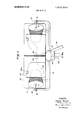
- FIG. 4 is a view partly in vertical elevation and partly in section, illustrating an intermediate weft thread storage device which can be used in the weft bobbin stand of the invention.
- FIG. 5 is a sectional view taken on the line 2-2 of FIG. 4.
- the stand of the invention is generally indicated at l, disposed at the picking side of a loom generally indicated at 2.
- reference character 3 identifies the cloth beam, the picking and catching side frame members thereof being identified at reference characters 30 and 31.
- the main drive motor 4 drives the main loom shaft through a belt connection to a combined flywheel and clutch 5.
- Reference character 6 identifies heddle frames for formation of a shed.
- the picking mechanism is indicated at 7 and a gripper shuttle is shown at 9 passing through the shed to a catcher 8.
- One or more weft threads 23 may be simultaneously picked through the shed by meansof the same shuttle.
- the catching mechanism 8 may be moved back towards the picking side, for example to the position indicated at 8a in dot-dash lines.
- the shuttle is braked to a stop in the catcher and is returned or restored a short distance toward the picking side of the loom in order to-compensate for irregularities in the distance required for braking.
- the weft is similarly drawn back toward the picking side by means of a thread tensioner 10. his then grasped by edge clamps not shown and cutoff on the picking side. The weft so inserted is then beaten up by the reed and is bound into thecloth with the next shed change.
- the weft ends initially extending beyond the edges of the cloth are tucked into the next shed by means of tuck-in needles not shown and are beaten up with the next weft to form a secure selvage.
- the heddles 6 are driven by a dobby 11, for example of the card or eccentric type, which can also control the weft feeders for selection in proper order of wefts from the various pairs of weft bobbins 22 (FIG. 2) in the creel 13 of thestand 1 in FIG. 1.
- a dobby 11 for example of the card or eccentric type
- one or more intermediate weft thread storage devices 12 are provided in accordance with the invention in the stand 1, downstream (in the sense of weft thread motion) of the bobbins 22 or of their respective thread-guiding eyes 24 in the creel.
- These intermediate weft thread storage devices may be of the type disclosed in the copending application Ser. No. 584,131 now US. Pat. No.
- a weft thread brake 24a disposed in the stand 1 between each of the eyes 24 and its intermediate weft thread storage device 12 serves to effect withdrawal of the weft threads in optimum fashion and with formation of a thread balloon between the bobbins 22 and eye 24, for delivery at substantially constant tension through the devices 12 and the exit guide eyes 29 of the stand to the entrance eyes 32 of the loom.
- the devices 12 are driven by means of common motor 12a, mounted on the stand, the motor being energized via a flexible cord 12b connecting to a power outlet on the loom.
- the creel 13 is fastened to the base 27 of the stand 1 by means of a strut 14 and is so disposed that in operating condition it is located above the thread -feeding devices 10 of the loom at the picking side thereof.
- the base 27 is supported on wheels 35.
- the creel 13 is disposed above the weaving plane and is rotatable about a vertical axis on a bearing 15.
- FIG. 4 Apparatus suitable to constitute each of the intermediate weft thread storage devices 12 is shown in FIG. 4.
- the device of FIG. 4 includes a set of bearings generally indicated at 124 supported on the arm 123.
- the ball bearings proper are shown at 125.
- a hollow shaft 126 is supported by means of ball bearing races from the bearing support 124.
- a pulley 127 mounted to turn freely on the shaft 126'. This pulley is driven by means of a belt 128 from the drive pulley 129 of a motor 120.
- the pulley 127 has affixed thereto a clutch plate 132 which cooperates by means of a magnetic coupling with a disc 133 fixed on the shaft 126.
- the disc 133 includes electromagnets 134 which can be energized via brushes 135 in a circuit including a switching device 136. When the magnetic coupling is energized, rotation of the disc 132 is imparted to the shaft 126.
- the shaft 126 includes an extension 142 inside the hollow cone 139.
- a drum 144 is rotatably supported with respect to the shaft in this space via ball bearings 143. Whereas the shaft 126 with its end 142 rotates, the drum 144 is held stationary as will hereinafter be further explained.
- the drum 144 At its left end as seen in FIG. 4, the drum 144 includes a conical enlargement 145 disposed substantially in the plane defined by the rotating eye 141, which plane is normally vertical.
- the right end of the drum 144 as seen in FIG. 4 is disposed within a ring 146 affixed to the support arm 123 so as to leave an annular space 147 between the ring and the drum.
- the ring 146 supports two permanent magnets 148 as shown in FIG. 5.
- the cylinder 144 carries two armatures or keepers 149 which cooperate with the magnets 148. In this way the drum 144 is prevented from following the rotation of the elements 126, 139, 141 and 142.
- the support arm 123 additionally carries a light source 151 whose beam 152 is obliquely incident on the drum 144.
- the reflected beam 153 impinges on a photocell 154 which is shielded from the source 151 by means of a mask 150.
- the photocell is connected by conductors 155 to the switching device 136;
- the source 151 and switching device are additionally connected via conductors 156 and 157 to a source of voltage 158.
- the mode of operation is as follows:
- the motor 12a is energized from a voltage source 130, and rotates.
- the hollow shaft 126 rotates with its cone 139 at uniform speed.
- the weft thread 110 is fed from the bobbin 22 through an eye 24 and through a thread tensioner 164 into the hollow shaft 126.
- the thread emerges from the shaft at 138 to pass outside the cone 139 and then through the rotating eye 141 toward the axis of the shaft.
- a number of turns of the weft thread are built up on the drum.
- the arrangement is such that the turn nearest the eye 141 is formed on the conical enlargement 145 of the drum.
- the drum has a polished surface so that the arriving coils cause those already wound to slip to the right in FIG. 4 and thus move onto the cylindrical portion of the drum. After a number of revolutions have been executed by theshaft, several such turns will build up on that cylindrical portion. By reason of the polished nature of the drum surface and because of the looseness with which the turns are wound, each turn will be shifted to the right by the turn to the left of it.
- the thread 110 is pulled off the stationary drum 144 toward the right, in FIG. 4, passing through the annular space 147. As may be seen from FIG. 4, no balloon of thread forms in the region 110a. The thread then passes through an eye 29.
- the average axial length 173 of the space occupied by the turns of thread on the drum 144 which axial length is so far as possible to be maintained constant, is desirably made of such size that the length of the thread wound up on the drum corresponds approximately to the width of the cloth, i.e. to the length of one pick. If the axial length 173 of the space occupied by the coils on the drum extends to the right so as to cover the point 174 at which the light beam 152 is reflected, the reflected beam 153 will be interrupted, reflection occurring at most in a diffuse manner from the thread on the drum.
- the photocell 154 and the switching device 136 are so adjusted that with this reduction of light incident on the photocell, the supply of current to the magnetic coupling 132, 133, 134 is interrupted.
- the hollow shaft 126 and cone 139 accordingly come to rest and the further accumulation of thread on the drum 144 is temporarily halted, whereas the elements 131, 129,127 and 132 continue to'rotate.
- the construction of the creel itself may be of the type disclosed in the copending application entitled WEFT BOBBIN CREEL, above-identified. Details thereof are shown in FIGS. 2 and 3.
- the creel includes a hub 16 resting on the bearing 15 with a cam 18 on the hub and a notch 18a on the bearing to prevent inadvertent rotation of the creel and consequent tangling of the threads.
- Spoke-like arms 17 are affixed to the hub 16.
- a hinge 20 rotatable about a vertical axis and having affixed thereto an arm 19 carrying at its end a stub shaft 21.
- the arms 19 are substantially tangential to the circular array of bobbins, so that the stub shafts 21 are directed radially inward for support of the bobbins 22.
- FIG. 2 two adjacent bobbins 22 are shown combined into a pair with the inner end of the thread of the first bobbin connected to the outer end of the second.
- the two bobbins of each pair are disposed inside a screen 25 which limits the size of the thread balloon formed from thread pulled from either of those spools.
- a partition wall 26 is disposed between the two spools of each pair with a pad of felt 26a on its upper edge and onto which there may be laid the connecting thread between the two spools.
- the screen 25 and par tition 26 are advantageously made of transparent material and fastened to the arm 17.
- the thread after passing through the eye 24, passes downwardly through the hub 16 and the hollow bearing 15, through a thread brake 24a and thence to the intermediate weftthread storage device 12 and to its exit eye 29 from the stand 1.
- the stand can be fastened to the loom by means of a coupler or linkage 28. Since however the only forces exerted between the stand and the loom are those produced by the weft threads being pulled from the creel, which forces are negligible, the coupling 28 can be dispensed with and the stand can be fixed in position with respect to the loom by means of a brake 33, operating on the wheels 35 thereof.
- the invention is not limited to the embodiment disclosed.
- a plurality of creels 13 can be provided superposed one above another.
- the bobbins 22 can be supported in a movable stand to be positioned substantially in the weaving plane to the left of the intermediate weft thread storage devices 12 as seen in FIG. 1.
- the invention includes all modifications of and departures from the embodiment shown properly falling within the spirit and scope of the appended claims.
- a movable weft bobbin stand comprising a base, means to support a plurality of bobbins on the base, and at least one intermediate weft thread storage device mounted on the base, each of said devices including a substantially cylindrical body rotatably mounted from one end thereof whereby a weft thread wound onto said body may be pulled off the other and thereof, means to wind a weft thread onto said body, and means to energize said winding means to maintain on said body a number of turns of weft thread between limiting minimum and maximum values.
- a movable weft bobbin stand according to claim 1 5 including wheels for support of said base.
- a movable weft bobbin stand according to claim 2 including a brake operating on the wheels thereof.
Landscapes
- Engineering & Computer Science (AREA)
- Textile Engineering (AREA)
- Looms (AREA)
Applications Claiming Priority (1)
| Application Number | Priority Date | Filing Date | Title |
|---|---|---|---|
| CH1247967A CH479731A (de) | 1967-09-06 | 1967-09-06 | Fahrbares Spulengestell für Webmaschinen |
Publications (1)
| Publication Number | Publication Date |
|---|---|
| US3693904A true US3693904A (en) | 1972-09-26 |
Family
ID=4383393
Family Applications (1)
| Application Number | Title | Priority Date | Filing Date |
|---|---|---|---|
| US95396A Expired - Lifetime US3693904A (en) | 1967-09-06 | 1970-12-04 | Weft bobbin stand |
Country Status (7)
| Country | Link |
|---|---|
| US (1) | US3693904A (cs) |
| AT (1) | AT272223B (cs) |
| CH (1) | CH479731A (cs) |
| CS (1) | CS152305B2 (cs) |
| DE (2) | DE1710355C3 (cs) |
| FR (1) | FR1579309A (cs) |
| GB (1) | GB1237766A (cs) |
Cited By (11)
| Publication number | Priority date | Publication date | Assignee | Title |
|---|---|---|---|---|
| US4454997A (en) * | 1982-03-04 | 1984-06-19 | Leesona Corporation | Inlet guide means for strand user devices |
| US4540138A (en) * | 1984-04-09 | 1985-09-10 | Alandale Knitting Company | Textile yarn creel |
| US4572458A (en) * | 1984-11-14 | 1986-02-25 | American Barmag Corporation | Compact creel for large diameter yarn supply packages |
| US4948067A (en) * | 1989-12-05 | 1990-08-14 | Alandale Industries, Inc. | Textile Yarn Creel |
| US5107904A (en) * | 1989-03-02 | 1992-04-28 | Sulzer Brothers Limited | Loom having a compact bobbin holder |
| US5323982A (en) * | 1993-01-08 | 1994-06-28 | Ligon Lang S | Low profile yarn supply apparatus for a loom having pneumatic yarn threading |
| US5624082A (en) * | 1995-09-11 | 1997-04-29 | Ligon; Lang S. | In-line yarn feed creel |
| US5806773A (en) * | 1996-03-22 | 1998-09-15 | Sucker-Muller-Hacoba Gmbh & Co. | Creel with antiballooning guides |
| US5857497A (en) | 1985-08-05 | 1999-01-12 | Wangner Systems Corporation | Woven multilayer papermaking fabric having increased stability and permeability |
| US20070084960A1 (en) * | 2005-10-11 | 2007-04-19 | Invista North America S.A.R.L. | Compact single mandrel creel for over end take-off thread delivery |
| US20190010637A1 (en) * | 2015-08-03 | 2019-01-10 | Btsr International S.P.A. | Storage yarn feeder with braking organ and interchangeable elements |
Families Citing this family (1)
| Publication number | Priority date | Publication date | Assignee | Title |
|---|---|---|---|---|
| CN112278988B (zh) * | 2020-11-10 | 2022-09-27 | 湖南大力科技咨询有限公司 | 一种纺织原料转运装置 |
Citations (3)
| Publication number | Priority date | Publication date | Assignee | Title |
|---|---|---|---|---|
| US2527700A (en) * | 1945-07-26 | 1950-10-31 | Nye Wait Company Inc | Portable loom creel and tensioning means therefor |
| US3168911A (en) * | 1961-11-10 | 1965-02-09 | Sulzer Ag | Looms |
| US3276484A (en) * | 1964-01-28 | 1966-10-04 | Sulzer Ag | Gripper shuttle type looms |
-
1967
- 1967-09-06 CH CH1247967A patent/CH479731A/de not_active IP Right Cessation
- 1967-09-12 AT AT832267A patent/AT272223B/de active
- 1967-11-25 DE DE1710355A patent/DE1710355C3/de not_active Expired
- 1967-11-25 DE DE6610222U patent/DE6610222U/de not_active Expired
-
1968
- 1968-09-03 GB GB41880/68A patent/GB1237766A/en not_active Expired
- 1968-09-05 FR FR1579309D patent/FR1579309A/fr not_active Expired
- 1968-09-06 CS CS6266A patent/CS152305B2/cs unknown
-
1970
- 1970-12-04 US US95396A patent/US3693904A/en not_active Expired - Lifetime
Patent Citations (3)
| Publication number | Priority date | Publication date | Assignee | Title |
|---|---|---|---|---|
| US2527700A (en) * | 1945-07-26 | 1950-10-31 | Nye Wait Company Inc | Portable loom creel and tensioning means therefor |
| US3168911A (en) * | 1961-11-10 | 1965-02-09 | Sulzer Ag | Looms |
| US3276484A (en) * | 1964-01-28 | 1966-10-04 | Sulzer Ag | Gripper shuttle type looms |
Cited By (14)
| Publication number | Priority date | Publication date | Assignee | Title |
|---|---|---|---|---|
| US4454997A (en) * | 1982-03-04 | 1984-06-19 | Leesona Corporation | Inlet guide means for strand user devices |
| US4540138A (en) * | 1984-04-09 | 1985-09-10 | Alandale Knitting Company | Textile yarn creel |
| US4572458A (en) * | 1984-11-14 | 1986-02-25 | American Barmag Corporation | Compact creel for large diameter yarn supply packages |
| US5857497A (en) | 1985-08-05 | 1999-01-12 | Wangner Systems Corporation | Woven multilayer papermaking fabric having increased stability and permeability |
| US5107904A (en) * | 1989-03-02 | 1992-04-28 | Sulzer Brothers Limited | Loom having a compact bobbin holder |
| US4948067A (en) * | 1989-12-05 | 1990-08-14 | Alandale Industries, Inc. | Textile Yarn Creel |
| EP0607832A1 (de) * | 1993-01-08 | 1994-07-27 | Lang Ligon And Company, Inc. | Garnliefer-Vorrichtung |
| US5323982A (en) * | 1993-01-08 | 1994-06-28 | Ligon Lang S | Low profile yarn supply apparatus for a loom having pneumatic yarn threading |
| US5624082A (en) * | 1995-09-11 | 1997-04-29 | Ligon; Lang S. | In-line yarn feed creel |
| US5806773A (en) * | 1996-03-22 | 1998-09-15 | Sucker-Muller-Hacoba Gmbh & Co. | Creel with antiballooning guides |
| US20070084960A1 (en) * | 2005-10-11 | 2007-04-19 | Invista North America S.A.R.L. | Compact single mandrel creel for over end take-off thread delivery |
| US7731119B2 (en) | 2005-10-11 | 2010-06-08 | INVISTA North America S.á rL. | Compact single mandrel creel for over end take-off thread delivery |
| US20190010637A1 (en) * | 2015-08-03 | 2019-01-10 | Btsr International S.P.A. | Storage yarn feeder with braking organ and interchangeable elements |
| US10655253B2 (en) * | 2015-08-03 | 2020-05-19 | Btsr International S.P.A. | Storage yarn feeder with braking organ and interchangeable elements |
Also Published As
| Publication number | Publication date |
|---|---|
| FR1579309A (cs) | 1969-08-22 |
| GB1237766A (en) | 1971-06-30 |
| CS152305B2 (cs) | 1973-12-19 |
| DE1710355C3 (de) | 1973-12-06 |
| DE1710355A1 (de) | 1972-04-20 |
| DE1710355B2 (de) | 1973-05-03 |
| DE6610222U (de) | 1973-06-20 |
| CH479731A (de) | 1969-10-15 |
| AT272223B (de) | 1969-06-25 |
Similar Documents
| Publication | Publication Date | Title |
|---|---|---|
| US3411548A (en) | Weft thread supply apparatus for gripper shuttle looms | |
| US3693904A (en) | Weft bobbin stand | |
| US3759300A (en) | Intermediate weft thread supply apparatus for looms | |
| US3761031A (en) | Storage apparatus for filamentary material | |
| JPS6245342B2 (cs) | ||
| HU9600063D0 (en) | Casting up stand | |
| KR100388371B1 (ko) | 씨실모니터용장치를갖는원형직기 | |
| CS277589B6 (en) | Thread feeding device for textile machines, particularly for weaving machines | |
| US3902644A (en) | Apparatus for the treatment of yarn | |
| US4799517A (en) | Weft yarn store for a loom | |
| US3526253A (en) | Weft bobbin creel | |
| US3411547A (en) | Weft thread supply apparatus for looms | |
| US3276484A (en) | Gripper shuttle type looms | |
| US2710631A (en) | Selvage thread feeding means for looms | |
| JPH06104943B2 (ja) | 織機用ヨコ糸貯蔵器 | |
| EP0580267B1 (en) | A device for feeding a periodically operating yarn-consuming device | |
| US3542084A (en) | Thread feeding device and process | |
| US3470922A (en) | Unwinding device for filling furnishing mechanism | |
| JPS621024B2 (cs) | ||
| JP2798734B2 (ja) | 環状織機のよこ糸補充方法及び装置 | |
| SU279509A1 (cs) | ||
| US1372315A (en) | Setts | |
| US3041007A (en) | Spinning packages | |
| US2114093A (en) | Silk throwing and quill or cop forming apparatus | |
| SU1467105A1 (ru) | Устройство дл подготовки уточных нитей к прокладыванию на бесчелночном ткацком станке |