US3599756A - Rock drill feed mast with integral muffler and oil separator - Google Patents
Rock drill feed mast with integral muffler and oil separator Download PDFInfo
- Publication number
- US3599756A US3599756A US33475A US3599756DA US3599756A US 3599756 A US3599756 A US 3599756A US 33475 A US33475 A US 33475A US 3599756D A US3599756D A US 3599756DA US 3599756 A US3599756 A US 3599756A
- Authority
- US
- United States
- Prior art keywords
- drill
- plate
- exhaust
- compressed gas
- chamber
- Prior art date
- Legal status (The legal status is an assumption and is not a legal conclusion. Google has not performed a legal analysis and makes no representation as to the accuracy of the status listed.)
- Expired - Lifetime
Links
- 239000011435 rock Substances 0.000 title description 11
- 239000007789 gas Substances 0.000 abstract description 57
- 239000007787 solid Substances 0.000 abstract description 12
- 230000036961 partial effect Effects 0.000 description 6
- 230000000694 effects Effects 0.000 description 4
- 230000009467 reduction Effects 0.000 description 4
- 125000006850 spacer group Chemical group 0.000 description 4
- 230000001050 lubricating effect Effects 0.000 description 3
- 238000005461 lubrication Methods 0.000 description 3
- 238000004891 communication Methods 0.000 description 2
- 239000007788 liquid Substances 0.000 description 2
- 239000000463 material Substances 0.000 description 2
- 230000004048 modification Effects 0.000 description 2
- 238000012986 modification Methods 0.000 description 2
- 238000005507 spraying Methods 0.000 description 2
- 239000011358 absorbing material Substances 0.000 description 1
- 230000009471 action Effects 0.000 description 1
- 238000004140 cleaning Methods 0.000 description 1
- 238000010276 construction Methods 0.000 description 1
- 230000002950 deficient Effects 0.000 description 1
- 230000008014 freezing Effects 0.000 description 1
- 238000007710 freezing Methods 0.000 description 1
- 230000002401 inhibitory effect Effects 0.000 description 1
- 230000014759 maintenance of location Effects 0.000 description 1
- 230000007257 malfunction Effects 0.000 description 1
- 230000007246 mechanism Effects 0.000 description 1
- 238000000034 method Methods 0.000 description 1
- 230000037361 pathway Effects 0.000 description 1
- 230000002829 reductive effect Effects 0.000 description 1
- 230000000717 retained effect Effects 0.000 description 1
- 238000000926 separation method Methods 0.000 description 1
- 238000004513 sizing Methods 0.000 description 1
- 238000006467 substitution reaction Methods 0.000 description 1
Images


Classifications
-
- E—FIXED CONSTRUCTIONS
- E21—EARTH OR ROCK DRILLING; MINING
- E21B—EARTH OR ROCK DRILLING; OBTAINING OIL, GAS, WATER, SOLUBLE OR MELTABLE MATERIALS OR A SLURRY OF MINERALS FROM WELLS
- E21B7/00—Special methods or apparatus for drilling
- E21B7/02—Drilling rigs characterised by means for land transport with their own drive, e.g. skid mounting or wheel mounting
- E21B7/025—Rock drills, i.e. jumbo drills
-
- B—PERFORMING OPERATIONS; TRANSPORTING
- B25—HAND TOOLS; PORTABLE POWER-DRIVEN TOOLS; MANIPULATORS
- B25D—PERCUSSIVE TOOLS
- B25D17/00—Details of, or accessories for, portable power-driven percussive tools
- B25D17/11—Arrangements of noise-damping means
- B25D17/12—Arrangements of noise-damping means of exhaust silencers
-
- E—FIXED CONSTRUCTIONS
- E21—EARTH OR ROCK DRILLING; MINING
- E21B—EARTH OR ROCK DRILLING; OBTAINING OIL, GAS, WATER, SOLUBLE OR MELTABLE MATERIALS OR A SLURRY OF MINERALS FROM WELLS
- E21B19/00—Handling rods, casings, tubes or the like outside the borehole, e.g. in the derrick; Apparatus for feeding the rods or cables
- E21B19/08—Apparatus for feeding the rods or cables; Apparatus for increasing or decreasing the pressure on the drilling tool; Apparatus for counterbalancing the weight of the rods
- E21B19/084—Apparatus for feeding the rods or cables; Apparatus for increasing or decreasing the pressure on the drilling tool; Apparatus for counterbalancing the weight of the rods with flexible drawing means, e.g. cables
-
- Y—GENERAL TAGGING OF NEW TECHNOLOGICAL DEVELOPMENTS; GENERAL TAGGING OF CROSS-SECTIONAL TECHNOLOGIES SPANNING OVER SEVERAL SECTIONS OF THE IPC; TECHNICAL SUBJECTS COVERED BY FORMER USPC CROSS-REFERENCE ART COLLECTIONS [XRACs] AND DIGESTS
- Y10—TECHNICAL SUBJECTS COVERED BY FORMER USPC
- Y10S—TECHNICAL SUBJECTS COVERED BY FORMER USPC CROSS-REFERENCE ART COLLECTIONS [XRACs] AND DIGESTS
- Y10S173/00—Tool driving or impacting
- Y10S173/02—Sound muffling
Definitions
- a muffler element having two spaced plates is located in an expansion chamber between the exhaust ports on the drill and the guide mast.
- One of these plates is solid and acts as a baffle; the other of these plates is perforated and is placed adjacent to the openings in the guide mast whereby exhaust gases are deflected by the muffler structure and flow around the muffler structure and through the perforated plate.
- This invention relates to the field of pneumatic tools. More particularly, this invention relates to a system for both muffling the exhaust of pneumatic tools, especially drill-type tools movably mounted on a guide mast, and also for lubricating operating parts with oil separated from the exhaust.
- U.S. Pat. No. 3,385,395 can malfunction due to clogging of the long flexible hose connecting the exhaust port of the drill motor with the inlet in the ho]- low drill mast.
- the hose has to be long enough to allow for full travel of the drill along the drill mast; it adds weight to the drill; and it may introduce undesired back pressure on the drill.
- the drop in temperature ac companying the expansion of the air often causes freezing of the moisture vapor in the exhaust as the exhaust travels through the hose, therefore clogging the hose.
- this invention sets forth apparatus wherein a compressed gas actuated working tool is adapted to travel along guide means mounted on a boxlike walled support structure.
- a plurality of openings or orifices in an outer surface of the walled support structure are disposed in relation to the exhaust structure of the working tool so that the exhaust is directed through the openings as the tool travels along the guide means.
- the exhaust enters an enclosure defined by the support structure where both the sound of the exhaust is muffled and entrained oil is separated from the exhaust to be used for lubricating purposes.
- the positioning of the openings on the outer surface of the support structure can be used to provide for automatic control, such as starting and stopping, of the working tool as it travels along the guide means.
- An expansion chamber is formed between the drill structure and the guide means whereby the exhaust gases immediately enter the expansion chamber upon leaving the drill structure prior to passing through the openings in the walled support structure.
- a double-plated muffler element is positioned in the expansion chamber immediately adjacent the walled structure. The plate closest to the support structure is perforated, and the other plate is solid. The exhaust gases from the drill impinge on the solid plate and are deflected around the ends thereof and then pass between the two plates and through the perforated plate into the openings of the support structure.
- one object of the present invention is to provide a novel and improved pneumatic tool wherein the exhaust noise is reduced.
- Another object ofthe present invention is to provide a novel and improved pneumatic tool wherein the exhaust is directed into an enclosure to prevent indiscriminate spraying of the ex haust to the surrounding environment.
- Still another object of the present invention is to provide a novel and improved pneumatic tool wherein oil in the exhaust is separated as the exhaust is muffled and then used for lubrication.
- Still another object of the present invention is to provide a novel and improved pneumatic tool wherein the exhaust from a working device is directed into the interior of the support structure on which the working device is mounted for travel to muffle the sound of the exhaust without requiring any flexible conduits connecting the working device to the interior of the support structure.
- Still another object of the present invention is to provide a novel and improved pneumatic tool wherein the exhaust from a working device is directed into an expansion chamber having a muffler element therein and thence into the interior of support structure on which the working device is mounted.
- Still another object of the present invention is to provide a novel and improved pneumatic tool wherein the exhaust from a working device is immediately directed into an expansion chamber wherein a double-plated muffler device is located, one of the plates being a solid baffle plate and the other plate being a perforated plate to allow passage of the exhaust gas.
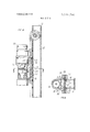
- FIG. I is a side elevation of a tractor mounted rock drill incorporating the features ofthe present invention.
- FIG. 2 is a partial side view in partial section of the upper end of a rock drill and mast assembly built in accordance with the teachings of the invention.
- FIG. 3 is a section along lines 3-3 of FIG. 2.
- FIG. 4 is a partial front view of the rock drill and drill mast assembly shown in FIG. 2.
- FIG. 5 is a partial side view in partial section of another embodiment of the rock drill and drill mast assembly incorporating the features of the invention.
- FIG. 6 is a partial front view of the rock drill and drill mast assembly shown in FIG. 5.
- FIG. 7 is a section along lines 7-7 of FIG. 5.
- FIG. 8 is a view similar to FIG. 2 showing the modification incorporating the double-plated muffler.
- FIG. 9 is a view similar to FIG. 3 taken along line 9-9 of FIG. 8.
- FIG. 1 shows a compressed gas actuated assembly in the form of a rock drill system consisting of a crawler 10 with a frame 12 from which a drill mast 14 is supported by means of a plurality of hydraulic cylinders 16. As is standard in the art, the mast is positioned by means of the hydraulic cylinders 16 and a power cone cylinder 18.
- a pneumatic drill apparatus shown generally at 20 is mounted on drill mast 14.
- a drill rod 22 extends from the drill apparatus 20 past the bottom of the drill mast 14 and is positioned by a drill centralizer 24 protruding from the bottom of the drill mast 14.
- a foot support 26 extending from the bottom of the drill mast 14 is used to anchor the drill mast during operations of the drill.
- the upper end 28 and the lower end 30 of drill mast 14 may, in accordance with the present invention, be either open or closed.
- the hoses and other accessory equipment used to deliver compressed air to the drill are known in the art and are omitted here for purposes ofsimplicity.
- the drill mast is constructed from a box section member generally indicated at 32, having sidewalls 34 and 36, a front wall 38 and rear wall 40, all of which cooperate to define an enclosed elongated space or chamber designated generally at 42 which extends substantially the entire length of drill mast 14.
- a rear stiffening plate 44 is welded to rear wall 40, and a front stiffening plate 46 is welded to rear wall 40, and a front stiffening plate 46 iS welded to the front wall of the box section.
- the edges of front stiffening plate 46 protrude beyond the sidewalls 34 and 36 of the box section to form a pair of guides 48.
- Each guide has an upper surface 50 and a lower surface 52.
- a drill motor generally identified at 54 is mounted on drill mast 14.
- the motor has a drill motor housing 56 which encloses a valve 58 used to control the flow of compressed gas to actuate the piston 60 which piston produces the impact action of the drill.
- the drill housing is slidably mounted on the drill guides 48 by a multielement mounting means.
- a wear plate 64 and a clamping plate 66 are in slidable contact with the upper guide surfaces 50 and the lower guide surfaces 52 respectively of drill guides 48.
- a shim 68 is disposed between wear plate 64 and clamping plate 66 to space the wear plate from the clamping plate to prevent the plates from squeezing the drill guides and thereby inhibiting the sliding motion of these elements on the drill guides.
- the drill motor housing 56 is rigidly connected to a drill mount 62, sometimes referred to as a slabback," by means of bolting lugs 70 protruding from walls 72 which in turn extend from the drill motor housing 56.
- the drill motor housing is moved along the length of the drill mast 14 by means of a feed motor 76, shown in FIG. 1 which draws a chain 78 connected to the drill motor mount 62 at a forward chain attaching point 80 and a rear chain attaching point 82.
- the chain runs alongthe front of the drill mast l4 and then passes through a slot 87 near mast top 28 and into the interior chamber 42 of the drill mast as shown in FIG. 3 The chain then runs down the drill mast inside chamber 42 and emerges near the bottom of the mast.
- the chain drive mechanism is fairly conventional as shown by the upper half of the system in FIG. 2.
- the chain 78 runs over a sprocket 84 mounted to the drill mast by means of an axle 86.
- a similar sprocket arrangement is provided at the bottom of the drill mast but is not shown for purposes of simplicity.
- the chain is fed to the advance motor through a slot in the back of the drill mast and a conventional chain guide system which have also not been shown for purposes of simplicity.
- Exhaust Means for Drill Motor Compressed gas used to actuate the drill by reciprocating the piston 60 leaves the drill motor housing 56 through exhaust ports 88 when, as shown schematically in FIG. 2, piston 60 is in a position which uncovers the exhaust ports.
- the compressed gas exhausted through exhaust ports 88 enters a plenum chamber 90 formed by walls 72 and passes through a drill mount passage 92 and wear plate passage 94 and finally passes into elongated chamber 42 through a plurality of drill guide exhaust openings or orifices 96 located in the front stiffening plate 46 and front wall 38 of the drill mast 14.
- the plenum chamber 90 and the passages in the wear plate 64 and drill mount 62 form a manifold which conducts the compressed gas leaving exhaust ports 88 into the drill guide exhaust orifices which are in turn in communication with chamber 42.
- the exhaust gas In traveling from exhaust 88 to plenum 90 and then to chamber 42, the exhaust gas passes through chambers or volumes of increasing size, and thus a distinct muffling or noise-reducing effect is obtained. After entering chamber 42 the exhaust gas expands and then flows, as indicated by the flow arrows, to the atmosphere through passages 96 which are open to atmosphere above the below drill mount 62. Since the drill is shown in FIG. 2 at the top of the mast, most of the exhaust flow is shown directed to passages below the drill; however, as the drill moves sown the mast there are open passages 96 above and below the drill through which exhaust gas passes to atmosphere.
- the elongated boxlike mast 14 by virtue of chamber 42, itself acts as a muffler chamber for the drill.
- the crosssectional box shape of mast l4 imparts added strength and rigidity to the mast and improves the dimensional integrity of the mast, especially the width, thereby minimizing side play or wobble of the drill on the mast.
- FIGS. 5, 6 and 7. A second embodiment of the invention is set forth in FIGS. 5, 6 and 7.
- the drill motor 20 shown in FIG. 5 includes a rotation motor 100 connected to the drill motor housing 56.
- the rotation motor is a separate compressed gas actuated device used to provide torque to the drill rod.
- the compressed gas used to actuate the rotation motor is discharged from the rotating motor through an exhaust port (not shown) into a rotation motor exhaust tube 102 which is connected to a passage 104 through one of the plenum walls 72.
- the compressed gas entering plenum chamber 90 through passage 104 then mixes with the compressed gas exhausted from the drill motor housing exhaust ports 88 and passes into the drill guide enclosure 42 through the drill guide exhaust pathways 96 as previously described.
- Sound-absorbing material 106 is disposed in the drill guide enclosure 42 to reduce the noise level produced by the exhaust from the drill motor and rotation motor as it enters the drill guide enclosure. Though shown disposed halfway between the front and rear walls of the drill mast, the soundabsorbing material could be disposed in many other convenient locations within the drill guide enclosure 42.
- the drill motor mount 62 has an elongated front skirt 108 extending along the drill mast forward of the drill motor mount, and an elongated rear skirt 100 extending along the drill mast behind the drill motor mount.
- the purpose of these skirts is to block off drill guide exhaust openings immediately in front of and behind the drill motor mount thereby requiring the compressed gas which has passed into the drill guide enclosure 42 to travel a greater distance before exiting to the ambient atmosphere through the uncovered drill guide exhaust openings. By extending the distance the gas must travel through the drill guide enclosure, increased sound reduction is achieved.
- a section of the front wall of the drill mast identified as 112 is solid and does not contain any of the drill guide exhaust openings 96.
- the drill mount 62 travels along the drill guides it will reach a position on the drill mast where the drill motor mount passage 92 and wear plate passage 90 are no longer in communication with any of the drill guide exhaust openings 96.
- the exhaust manifold consisting of the plenum chamber 90 and drill motor passage 92 and wear plate passage 94 coact with the solid section 112 to become a relatively air tight chamber.
- the pressure within the relatively airtight chamber will rapidly build up as the exhaust gas enters until the pressure in the airtight chamber is close to or equal to the pressure within the drill motor housing 56.
- Muffler 200 is composed of a pair of plates 202 and 204 separated by a pair of spacers o whereby a chamber 200 is formed between the plates 202 and 204.
- Plate 204 occupies substantially the entire area of drill mount passage 92, and plate 204 is perforated over its entire surface with a large number of small diameter passages 210 on the order of about one'eighth of an inch in diameter.
- Plate 202 is spaced from plate 204 on the side closer to exhaust ports 88, and spacers 206 are welded between the plates 202 and 204 to form a fixed structure.
- the length of solid plate 202 is less than the length of perforated plate 204 (FIG. 8) but the width of solid plate 202 is greater than the width of perforated plate 204 (FIG. 9).
- This relative sizing of these parts allows for retention of the muffler in the drill structure while enabling these parts to perform their function of diverting and muffling the exhaust gases.
- FlG. 9 the manner in which muffler 200 is retained in the drill structure is shown.
- the side edges 2l2 of plate 202 engage the ends of walls 72, and rubber spacer elements 214 are wedged between wear plates 64 and perforated plate 204.
- the rubber spacer elements 214 serve to force or wedge the ends of plate 202 against walls 72 thereby retaining the muffler structure in place.
- the exhaust gases from exhaust ports 88 enter into plenum chamber 90 as previously described.
- the gases are first caused to encounter and come under the influence of muffler 200.
- the gases exiting from exhaust 88 strike plate 202, which is positioned in the line of flow of the gases from exhaust 80.
- Solid plate 202 acts as a baffle plate whereby the direction of flow of the exhaust gases impinging thereon is varied so that the gases turn and flow along plate 202.
- These turned exhaust gases then flow around top and bottom edges, 216 and 218, respectively, of plate 202 whereby the direction of the gases is again turned.
- the gases then flow both into chamber 200 between plates 202 and 204 and through the many perforations of plate 204 to then pass through openings 96 into chamber 42 for ultimate exhaust to atmosphere as previously described.
- chamber 208 acts as a resonating chamber for the gas passing through that chamber, and the exhaust gases are caused to expand when passing through holes 210 as well as when first entering the expansion chamber and when passing through openings 96.
- solid plate 202 also forces the gases to travel a longer path then would otherwise be the case if they were allowed to proceed directly to passages 96.
- the multiple turning of the direction offlow of the gases and the resonating chamber effect and the additional expansion through holes 210 when the gases come under the influence of muffler 200 all result in a substantial reduction in the velocity of the exhaust gases and a substantial reduction in the noise level of these gases. Accordingly, in addition to all of the features of the embodiments previously discussed, the embodiment of FIGS. 0 and 9 produces a further significant reduction in the noise level of the exhaust gases.
- a compressed gas actuated device comprising:
- a compressed gas actuated tool mounted on said walled structure for travel along said walled structure;
- exhaust chamber means on said tool communicating with an exhaust port on said tool for exhausting working gas from said tool;
- said exhaust chamber means communicating with said internal chamber through at least one of said orifices to exhaust the working gas into said internal chamber.
- said second plate having a plurality of openings therethrough.
- a compressed gas actuated device as in claim 2 wherein:
- said first plate is of a size less than the cross-sectional size of said exhaust chamber at the location of said second plate.
- said first plate forms a baffle plate
- said first and second plates define a chamber therebetween'
- said second plate has openings therethrough distributed substantially uniformly spaced over the entire plate.
- a compressed gas actuated device as in claim 4 wherein:
- each of said first and second plates has a length and a width dimension, at least one of said dimensions of said second plate being greater than the corresponding dimension of said first plate.
- openings in said second plate communicate with said orifices in said walled structure, each of said openings in said second plate being smaller than one of said orifices in said walled structure.
- said tool and further including; retaining means urging said muffler means against the ends of said walls to retain said muffler means in position.
Landscapes
- Engineering & Computer Science (AREA)
- Geology (AREA)
- Life Sciences & Earth Sciences (AREA)
- Mining & Mineral Resources (AREA)
- Physics & Mathematics (AREA)
- Environmental & Geological Engineering (AREA)
- Fluid Mechanics (AREA)
- Mechanical Engineering (AREA)
- General Life Sciences & Earth Sciences (AREA)
- Geochemistry & Mineralogy (AREA)
- Earth Drilling (AREA)
- Percussive Tools And Related Accessories (AREA)
- Drilling And Exploitation, And Mining Machines And Methods (AREA)
Applications Claiming Priority (2)
| Application Number | Priority Date | Filing Date | Title |
|---|---|---|---|
| US85455169A | 1969-09-02 | 1969-09-02 | |
| US3347570A | 1970-04-30 | 1970-04-30 |
Publications (1)
| Publication Number | Publication Date |
|---|---|
| US3599756A true US3599756A (en) | 1971-08-17 |
Family
ID=26709751
Family Applications (1)
| Application Number | Title | Priority Date | Filing Date |
|---|---|---|---|
| US33475A Expired - Lifetime US3599756A (en) | 1969-09-02 | 1970-04-30 | Rock drill feed mast with integral muffler and oil separator |
Country Status (5)
| Country | Link |
|---|---|
| US (1) | US3599756A (OSRAM) |
| JP (1) | JPS4949282B1 (OSRAM) |
| CA (1) | CA926855A (OSRAM) |
| FR (1) | FR2060851A5 (OSRAM) |
| GB (1) | GB1291907A (OSRAM) |
Cited By (11)
| Publication number | Priority date | Publication date | Assignee | Title |
|---|---|---|---|---|
| US3757875A (en) * | 1971-11-24 | 1973-09-11 | Kent Air Tool Co | Air hammer and combined support and muffler therefor |
| US3993159A (en) * | 1975-01-06 | 1976-11-23 | Dresser Industries, Inc. | Muffler for a governed pneumatic tool |
| US4402383A (en) * | 1981-09-01 | 1983-09-06 | Joy Manufacturing Company | Drill motor enclosure |
| US20080115953A1 (en) * | 2004-10-07 | 2008-05-22 | Kurt Andersson | Rock Drilling Device |
| US20090090530A1 (en) * | 2007-07-13 | 2009-04-09 | Longyear Tm, Inc. | Noise abatement device for a pneumatic tool |
| US20090294211A1 (en) * | 2008-05-28 | 2009-12-03 | Longyear Tm, Inc. | Noise reducing device for a pneumatic tool |
| US20110126541A1 (en) * | 2009-12-02 | 2011-06-02 | Longyear Tm, Inc. | Muffler system for noise abatement and ice control |
| RU2554985C1 (ru) * | 2011-06-07 | 2015-07-10 | Сок Син ИН | Устройство опорной направляющей |
| EP2475839A4 (en) * | 2009-09-08 | 2018-02-14 | Sandvik Mining and Construction Oy | Rock drilling unit, feed beam, and method for damping vibration |
| CN110397406A (zh) * | 2019-08-21 | 2019-11-01 | 北京三一智造科技有限公司 | 旋挖钻机随动架滑耳及旋挖钻机随动架 |
| CN117027762A (zh) * | 2023-07-18 | 2023-11-10 | 中国科学院声学研究所 | 一种测井用扶正减震器 |
Families Citing this family (1)
| Publication number | Priority date | Publication date | Assignee | Title |
|---|---|---|---|---|
| CN102943630B (zh) * | 2012-10-30 | 2015-05-13 | 北京探矿工程研究所 | 一种轻便地质钻机通用钻架 |
Citations (2)
| Publication number | Priority date | Publication date | Assignee | Title |
|---|---|---|---|---|
| US2028320A (en) * | 1934-12-06 | 1936-01-21 | Cleveland Rock Drill Co | Rock drill supporting frame |
| US3385395A (en) * | 1966-05-02 | 1968-05-28 | Ingersoll Rand Co | Muffling system for compressed airoperated drilling apparatus |
-
1970
- 1970-04-30 US US33475A patent/US3599756A/en not_active Expired - Lifetime
- 1970-08-26 CA CA091693A patent/CA926855A/en not_active Expired
- 1970-09-02 GB GB41920/70A patent/GB1291907A/en not_active Expired
- 1970-09-02 FR FR7031942A patent/FR2060851A5/fr not_active Expired
- 1970-09-02 JP JP45076388A patent/JPS4949282B1/ja active Pending
Patent Citations (2)
| Publication number | Priority date | Publication date | Assignee | Title |
|---|---|---|---|---|
| US2028320A (en) * | 1934-12-06 | 1936-01-21 | Cleveland Rock Drill Co | Rock drill supporting frame |
| US3385395A (en) * | 1966-05-02 | 1968-05-28 | Ingersoll Rand Co | Muffling system for compressed airoperated drilling apparatus |
Cited By (18)
| Publication number | Priority date | Publication date | Assignee | Title |
|---|---|---|---|---|
| US3757875A (en) * | 1971-11-24 | 1973-09-11 | Kent Air Tool Co | Air hammer and combined support and muffler therefor |
| US3993159A (en) * | 1975-01-06 | 1976-11-23 | Dresser Industries, Inc. | Muffler for a governed pneumatic tool |
| US4402383A (en) * | 1981-09-01 | 1983-09-06 | Joy Manufacturing Company | Drill motor enclosure |
| US20080115953A1 (en) * | 2004-10-07 | 2008-05-22 | Kurt Andersson | Rock Drilling Device |
| US7628223B2 (en) * | 2004-10-07 | 2009-12-08 | Atlas Copco Rock Drills Ab | Rock drilling device |
| US20100155174A1 (en) * | 2007-07-13 | 2010-06-24 | Longyear Tm, Inc. | Noise abatement device for a pneumatic tool |
| US20090090530A1 (en) * | 2007-07-13 | 2009-04-09 | Longyear Tm, Inc. | Noise abatement device for a pneumatic tool |
| US7845464B2 (en) | 2007-07-13 | 2010-12-07 | Longyear Tm, Inc. | Noise abatement device for a pneumatic tool |
| US7681690B2 (en) | 2007-07-13 | 2010-03-23 | Longyear Tm, Inc. | Noise abatement device for a pneumatic tool |
| US7735603B2 (en) | 2008-05-28 | 2010-06-15 | Longyear Tm, Inc. | Noise reducing device for a pneumatic tool |
| US20090294211A1 (en) * | 2008-05-28 | 2009-12-03 | Longyear Tm, Inc. | Noise reducing device for a pneumatic tool |
| EP2475839A4 (en) * | 2009-09-08 | 2018-02-14 | Sandvik Mining and Construction Oy | Rock drilling unit, feed beam, and method for damping vibration |
| US20110126541A1 (en) * | 2009-12-02 | 2011-06-02 | Longyear Tm, Inc. | Muffler system for noise abatement and ice control |
| US8215449B2 (en) | 2009-12-02 | 2012-07-10 | Longyear Tm, Inc. | Muffler system for noise abatement and ice control |
| RU2554985C1 (ru) * | 2011-06-07 | 2015-07-10 | Сок Син ИН | Устройство опорной направляющей |
| CN110397406A (zh) * | 2019-08-21 | 2019-11-01 | 北京三一智造科技有限公司 | 旋挖钻机随动架滑耳及旋挖钻机随动架 |
| CN110397406B (zh) * | 2019-08-21 | 2024-04-19 | 北京三一智造科技有限公司 | 旋挖钻机随动架滑耳及旋挖钻机随动架 |
| CN117027762A (zh) * | 2023-07-18 | 2023-11-10 | 中国科学院声学研究所 | 一种测井用扶正减震器 |
Also Published As
| Publication number | Publication date |
|---|---|
| GB1291907A (en) | 1972-10-04 |
| JPS4949282B1 (OSRAM) | 1974-12-26 |
| CA926855A (en) | 1973-05-22 |
| DE2043582A1 (de) | 1971-03-04 |
| FR2060851A5 (OSRAM) | 1971-06-18 |
Similar Documents
| Publication | Publication Date | Title |
|---|---|---|
| US3635299A (en) | Muffler for pneumatic tool | |
| US6196331B1 (en) | Air supply and exhaust system for pneumatic tool | |
| US3856439A (en) | Sound proofed and air cooled shell for portable air compressor | |
| US3757875A (en) | Air hammer and combined support and muffler therefor | |
| US3224527A (en) | Percussive drill with noise silencer | |
| US2789653A (en) | Muffler attachment for air driven tools of the impact type | |
| US3255844A (en) | Multi-passage silencer for pneumatic tool | |
| CA1103114A (en) | Air hammer and muffler combination | |
| WO2004113699A1 (ja) | 建設機械のエンジンフード,建設機械のエンジンルーム構造及び建設機械の冷却装置 | |
| FI66558C (fi) | Ljuddaempare foer luftdrivna slagverktyg | |
| CA1156154A (en) | Power tool muffler cooling | |
| US2166218A (en) | Muffling device | |
| US3202239A (en) | Acoustic shield for a tool powered by a gas-operated motor | |
| US4079809A (en) | Muffler for pneumatic drill | |
| CN102597444B (zh) | 用于消除噪音和防冰控制的消音系统 | |
| GB1291907A (en) | Muffling the exhaust of compressed gas actuated tools | |
| US3547222A (en) | Rock drill feed mast with integral muffler and oil separator | |
| US3225861A (en) | Sound suppressing device comprising elastic tubular sleeve for air actuated percussive type tools | |
| US2924296A (en) | Dry muffler and mounting means therefor | |
| CA1207611A (en) | Pneumatically operated impact tool | |
| US3847232A (en) | Pneumatic percussive tool | |
| SU1093803A1 (ru) | Пневмоударный механизм | |
| JP3954924B2 (ja) | 空圧式固着具打込機の減音装置 | |
| JP3605419B2 (ja) | エゼクタ装置 | |
| JP2017160639A (ja) | 作業機械の排気装置 |