US3071083A - Monocable aerial ropeway - Google Patents
Monocable aerial ropeway Download PDFInfo
- Publication number
- US3071083A US3071083A US56793A US5679360A US3071083A US 3071083 A US3071083 A US 3071083A US 56793 A US56793 A US 56793A US 5679360 A US5679360 A US 5679360A US 3071083 A US3071083 A US 3071083A
- Authority
- US
- United States
- Prior art keywords
- cable
- line
- pulley
- stations
- roll
- Prior art date
- Legal status (The legal status is an assumption and is not a legal conclusion. Google has not performed a legal analysis and makes no representation as to the accuracy of the status listed.)
- Expired - Lifetime
Links
- 238000007665 sagging Methods 0.000 claims description 4
- 230000001276 controlling effect Effects 0.000 description 5
- 230000015572 biosynthetic process Effects 0.000 description 2
- 230000008878 coupling Effects 0.000 description 2
- 238000010168 coupling process Methods 0.000 description 2
- 238000005859 coupling reaction Methods 0.000 description 2
- 230000007812 deficiency Effects 0.000 description 2
- 239000000314 lubricant Substances 0.000 description 2
- 230000001105 regulatory effect Effects 0.000 description 2
- 208000008784 apnea Diseases 0.000 description 1
- 238000013459 approach Methods 0.000 description 1
- 230000005540 biological transmission Effects 0.000 description 1
- 230000002950 deficient Effects 0.000 description 1
- 238000009434 installation Methods 0.000 description 1
- 230000002093 peripheral effect Effects 0.000 description 1
- 239000004576 sand Substances 0.000 description 1
- 230000001360 synchronised effect Effects 0.000 description 1
Images
Classifications
-
- B—PERFORMING OPERATIONS; TRANSPORTING
- B61—RAILWAYS
- B61B—RAILWAY SYSTEMS; EQUIPMENT THEREFOR NOT OTHERWISE PROVIDED FOR
- B61B12/00—Component parts, details or accessories not provided for in groups B61B7/00 - B61B11/00
- B61B12/10—Cable traction drives
-
- B—PERFORMING OPERATIONS; TRANSPORTING
- B61—RAILWAYS
- B61B—RAILWAY SYSTEMS; EQUIPMENT THEREFOR NOT OTHERWISE PROVIDED FOR
- B61B12/00—Component parts, details or accessories not provided for in groups B61B7/00 - B61B11/00
Definitions
- the present invention relates to 'monocable aerial ropeways of the type having an endless cable and a rotary drive for the cable.
- aerial cableways are increasing, since this form of transport is relatively inexpensive. Moreover, it is in many cases the only available way for opening otherwise inaccessible regions to traffic.
- Chair-lifts are an example of a monocable aerial ropeway which are very popular as they are able to convey a large number of people at a minimum cost.
- the chair of the lift is not enclosed, thereby avoiding the necessity and consequent cost of an enclosure.
- Chair-lifts generally accommodate single chairs or two-seaters and the seats hang directly on an endless cable driven by an electromotor.
- Such a rotary drive for a cable of the above device has, however, a drawback in that it is not adaptable to the variations in weight of the load, so that the motor must operate at full power even though only a few persons are transported.
- the cable passes around a pair of grooved pulleys, one of which is driven, whereby the cable is driven in a closed loop path having parallel reaches moving in opposite directions.
- the driving of the motor at full power regardless of the magnitude of the load on the device, is a serious deficiency in transporting persons in absolute safety, since overload, low friction due to lubricants, or ice formation on the cable may cause the cable to slip in the groove of the drive pulley, resulting in accidents.
- An advantage offered by the present invention in providing a power supply and control therefor at the mountain station is that the loads of the opposite reaches of the cable are balanced. if there is only one power supply, for example, at the valley station and if a great number of persons or heavy loads are transported, the hauling portion of the cable, i.e. one of the reaches of the cable, will be highly stretched and taut, while the carrying portion or other reach of the cable will be relaxed the masts due to the load 13.
- the arrangement according to the invention eliminates the above disadvantage in that in cases where heavy loads are to be transported, the mountain station motor can be actuated to reduce the tension in the hauling portion of the cable and to increase the tension in the carrying portion to thereby avoid sagging of the carrying portion. This permits varying the size of the load While maintaining approximately equal tensile stresses in both reaches of the cable.
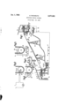
- ES. 1 is a diagrammatic View of the device according to the invention.
- FIGS. 2-5 show in detail various types of control means.
- the end stations of the aerial cable device hereinafter described as the mountain station and the valley station each are provided with a separate power supply, which power supplies are preferably of equal rating.
- the lower supply may be a motor I, II, such as an electromotor, a diesel motor or some other rotary drive.
- the motors I, II are each adapted to respectively, continuously drive grooved pulleys 1, in through couplings 4, 4a and gear 3, Be.
- a cable 9 is tensioned in known way by the counterweight 6 connected over the roll 10 to the movable support 11 of pulley 1.
- the magnitude of the tension in the cable 9 controls the sag of the cable between
- an emergency dynamo 14 adapted for use in the event of interruptions of current or of any other service difficulties that may occur in the power supply.
- the tension in the reaches of the cable are equal whereas in the single pulley drive devices only one reach is substantially stressed and the other is relaxed. This exposes the single pulley drive devices to the risks of slippage of the cable due to the high stress. This is of particular importance since the cable device according to the invention may be used in cold climates where ice and snow on the cable lowers the coeflicient of friction thereof and the use of excessive tension in the cable may apnoea result in slippage thereof. Similarly, the cables are of necessity lubricated and if excessive stress is provided in the cable, then the cable will slip on the pulleys.
- Another important advantage of the arrangement in accordance with the invention is that service must not necessarily be interrupted if one of the drive devices is out of service, since the other drive device may be operatcd. Service of the motor associated with the defective part can be switched oil and the other motor operated.
- the selector switch 7 it is possible, by operating the selector switch 7, to selectively energizes the motor I or the motor H, or to energize both motors simultaneously.
- the emergency dynamo is connected to the pulley to constitute the driving source to keep the installation in service. This is obtained by moving switch tl to the appropriate position.
- the invention also provides an automatic control of the power supplies by use of known means (such as thyratrons, ignitrons and the like) which regulate the energization of the second motor in relation with the magnitude of the energization on the cable load.
- known means such as thyratrons, ignitrons and the like
- FIGS. 2-5 show various types of control means capable of effecting the above operation.
- the control means is shown associated with pulley l for controlling the operation of motor ll.
- the control means may be associated with pulley 2a for controlling motor I if desired.
- a roll 15 supporting a finger i6 is rotatably mounted at the periphery of the grooved pulley 1 so as to project beyond the circumference of said pulley. As long as the friction between the cable 9 and the groove pulley 1 remains normal, the roll 15 remains fixed on its axis 17. Thus, roll 15 is supported on pulley 1 for rotation about axis 17.
- the cable 9 drives pulley 1 and roll 15 such that when no slippage between pulley 1 and cable 9 exists, roll 15 and pulley l have no relative movement. If the cable 9 starts slipping on pulley 1, i.e.
- the roll 15 rotates relative to the pulley 1 and the necessary synchronized movement of the periphery of roll 15 and the periphery of pulley 1 is upset and finger 16 contacts lug 18.
- the contact of finger 16 with lug it may be associated with the motor II on the other pulley to energize the same. This may be accomplished in conventional manner, wherein finger l6 and lug 18 constitute a switch for coupling an energy source to the motor II on the other pulley.
- FIGS. 3 and 4 show another embodiment of the controlling device in accordance with the invention.
- FIG. 3 is a top view of the device represented diagrammatically in FIG. 4.
- the cable 9 runs between the grooved pulley 1 and roll 19.
- a pendulum 20 is suspended from the roll 19 in freely oscillatable fashion such that the pendulum 20 assumes an angular position with respect to the roll 19.
- the roll rotates about the axis of rotation thereof.
- the pendulum is at an angle or with respect to the roll 19. If the velocity of the roll 19 exceeds the normal velocity, the angle a between the pendulum and the roll 19 increases. If the angle reaches an angle [3 the pendulum contacts the contact ring 21 which may be adapted to close a circuit, thereby switching on the second motor in a manner as shown in FIG. 2.
- FIG. is a schematic view of still another embodiment.
- Two rolls 22 and 23 of identical diameter are in contact, one with cable 9, the other with the grooved pulley 1.
- Each roll is connected to a small dynamo (not shown).
- the taps are coupled so that the dynamcs oppose one another and when the peripheral speed of the pulley is the same as the speed of the cable 9, i.e. no slippage, a zero voltage will be indicated at U.
- the control system in accordance with the invention furnishes complete safety against slippage of the cable, as the second motor is immediately switched on automatically as soon as sli page is detected. It is thus ascertained that the present invention supplies advantages from an economical point of view as well as with regard to the safety of transported persons and goods.
- a driving system for a cable way of the type having a movable endless line adapted to support and transport a load, the line extending between first and second stations, the driving system comprising means at each of said stations engaging said line in driving engagement to define a closed path therefor constituted by parallel reaches running in opposite directions, the line sagging under the influence of the load, means coupled to each of the first said means for driving the same to impart a drive to said line thereat, and control means coupled to the latter said means for selectively energizing the same in response to relative slippage between the line and the first said means at the stations whereby the line may be selectively driven at either of said stations and simultaneously at both said stations.
- a driving system for a cable way of the type having an endless line adapted to support a load, the line extending between first and second stations, the driving system comprising a pulley at each of said stations, the line passing around the pulleys to form a continuous closed loop path for the line constituted by parallel reaches running in opposite directions, one of the reaches constituting a hauling line and the other reach constituting a return line, the load being adapted to be supported on the hauling line, drive means coupled to each of said pulleys for driving the same, the hauling line sagging under the influence of the load, said line normally being in frictionally engagement with said pulleys to pass there-,
- control means normally energizing the drive means associated with one of said pulleys and adapted for selectively energizing the drive means associated with the other of said pulleys in response to slipping of said line around said pulleys whereby the line can be driven simultaneously at both said stations.
- control means comprises a roll rotatably supported on one of said pulleys, said line engaging said roll and said associated pulley to cause rotation thereof about respective axis of rotation such that the relative position of said roll with respect to said pulley is unchanged when slippage is absent between said line and the roll and pulley respectively, a finger extending from said roll, and a lug on said one pulley and normally spaced from said finger, said roll rotating with respect to said pulley in response to slippage between said line and said pulley to engage said lug, and energize the drive means associated with the other of said pulleys.
- a driving system as claimed in claim 2 comprising a roll engaging said one pulley at the periphery thereof, a second roll engaging the line around said one pulley, means operativcly associated with each of said rolls to 8,071,083 5 6 generate a voltage in response to the speed of rotation References Cited in the file of this patent thereof, the last said rneans associated with each roll being UNITED STATES PATENTS connected in opposing relatlon to normally cancel sa1d voltages, said voltages producing a difference when the 1,294,813 Lammert et a1 1919 line slips with respect to said one pulley and means re- 5 2,057,173 Waalkes 1936 sponsive to the diflference between said voltages to ener- O N
- PA 2:56:26 drive means assoclated mm the other of sand 1,070,763 France Feb. 24 1954
Landscapes
- Engineering & Computer Science (AREA)
- Transportation (AREA)
- Mechanical Engineering (AREA)
- Pulleys (AREA)
Applications Claiming Priority (2)
| Application Number | Priority Date | Filing Date | Title |
|---|---|---|---|
| CH7845859A CH373415A (de) | 1959-09-21 | 1959-09-21 | Antriebsvorrichtung an Transporteinrichtung |
| CH3071083X | 1959-09-21 |
Publications (1)
| Publication Number | Publication Date |
|---|---|
| US3071083A true US3071083A (en) | 1963-01-01 |
Family
ID=25738387
Family Applications (1)
| Application Number | Title | Priority Date | Filing Date |
|---|---|---|---|
| US56793A Expired - Lifetime US3071083A (en) | 1959-09-21 | 1960-09-19 | Monocable aerial ropeway |
Country Status (2)
| Country | Link |
|---|---|
| US (1) | US3071083A (de) |
| CH (1) | CH373415A (de) |
Cited By (13)
| Publication number | Priority date | Publication date | Assignee | Title |
|---|---|---|---|---|
| US3115847A (en) * | 1962-11-08 | 1963-12-31 | Gen Tech Inc | Aerial tramways |
| US3140670A (en) * | 1961-05-05 | 1964-07-14 | Doppelmayr & Sohn | Aerial cableways |
| US3274954A (en) * | 1963-05-10 | 1966-09-27 | Doppelmayr Emil | Cable operating control mechanism |
| US3302588A (en) * | 1964-07-07 | 1967-02-07 | Bennett William Frederick | Aerial tramway safety devices |
| US3377959A (en) * | 1966-04-01 | 1968-04-16 | Alan B. Hawes | Aerial cable roundabout |
| US3405478A (en) * | 1965-03-05 | 1968-10-15 | Lehmann Ernst Paul | Toy cable car device |
| US3728972A (en) * | 1971-05-19 | 1973-04-24 | Goforth Brothers Inc | Tension means for aerial tramways |
| US3951073A (en) * | 1974-12-04 | 1976-04-20 | Sowder Tony R | Self centering tension drive terminal for tramway |
| US4401034A (en) * | 1979-02-27 | 1983-08-30 | Cie Miniere De L'ogooue (Comilog) | Aerial cableway having a return sheave with a speed stabilization device |
| US4802416A (en) * | 1986-06-03 | 1989-02-07 | Konrad Doppelmayr & Sohn Maschinenfabrik Gesellschaft Mbh & Co. Kg | Cableway having a multipass lift cable |
| US20050263095A1 (en) * | 2004-05-05 | 2005-12-01 | Arno Inauen | Apparatus for exercising animals |
| US7290722B1 (en) | 2003-12-16 | 2007-11-06 | Snow Machines, Inc. | Method and apparatus for making snow |
| EP1757338A3 (de) * | 2005-08-26 | 2008-02-13 | Pieter Christoffel Maria Van Beers | Seilschwebebahn für Wasserski |
Families Citing this family (2)
| Publication number | Priority date | Publication date | Assignee | Title |
|---|---|---|---|---|
| AT2306U1 (de) * | 1997-07-16 | 1998-08-25 | Girak Garaventa Gmbh | Standseilbahn |
| AT405733B (de) * | 1997-07-16 | 1999-11-25 | Girak Garaventa Gmbh | Standseilbahn |
Citations (3)
| Publication number | Priority date | Publication date | Assignee | Title |
|---|---|---|---|---|
| US1294813A (en) * | 1917-10-23 | 1919-02-18 | Lammert And Mann Company | Traction system for package-trucks. |
| US2057173A (en) * | 1932-02-15 | 1936-10-13 | Anchor Steel & Engineering Co | Conveyer system |
| FR1070763A (fr) * | 1953-02-11 | 1954-08-12 | Installation pour la pratique du ski nautique |
-
1959
- 1959-09-21 CH CH7845859A patent/CH373415A/de unknown
-
1960
- 1960-09-19 US US56793A patent/US3071083A/en not_active Expired - Lifetime
Patent Citations (3)
| Publication number | Priority date | Publication date | Assignee | Title |
|---|---|---|---|---|
| US1294813A (en) * | 1917-10-23 | 1919-02-18 | Lammert And Mann Company | Traction system for package-trucks. |
| US2057173A (en) * | 1932-02-15 | 1936-10-13 | Anchor Steel & Engineering Co | Conveyer system |
| FR1070763A (fr) * | 1953-02-11 | 1954-08-12 | Installation pour la pratique du ski nautique |
Cited By (13)
| Publication number | Priority date | Publication date | Assignee | Title |
|---|---|---|---|---|
| US3140670A (en) * | 1961-05-05 | 1964-07-14 | Doppelmayr & Sohn | Aerial cableways |
| US3115847A (en) * | 1962-11-08 | 1963-12-31 | Gen Tech Inc | Aerial tramways |
| US3274954A (en) * | 1963-05-10 | 1966-09-27 | Doppelmayr Emil | Cable operating control mechanism |
| US3302588A (en) * | 1964-07-07 | 1967-02-07 | Bennett William Frederick | Aerial tramway safety devices |
| US3405478A (en) * | 1965-03-05 | 1968-10-15 | Lehmann Ernst Paul | Toy cable car device |
| US3377959A (en) * | 1966-04-01 | 1968-04-16 | Alan B. Hawes | Aerial cable roundabout |
| US3728972A (en) * | 1971-05-19 | 1973-04-24 | Goforth Brothers Inc | Tension means for aerial tramways |
| US3951073A (en) * | 1974-12-04 | 1976-04-20 | Sowder Tony R | Self centering tension drive terminal for tramway |
| US4401034A (en) * | 1979-02-27 | 1983-08-30 | Cie Miniere De L'ogooue (Comilog) | Aerial cableway having a return sheave with a speed stabilization device |
| US4802416A (en) * | 1986-06-03 | 1989-02-07 | Konrad Doppelmayr & Sohn Maschinenfabrik Gesellschaft Mbh & Co. Kg | Cableway having a multipass lift cable |
| US7290722B1 (en) | 2003-12-16 | 2007-11-06 | Snow Machines, Inc. | Method and apparatus for making snow |
| US20050263095A1 (en) * | 2004-05-05 | 2005-12-01 | Arno Inauen | Apparatus for exercising animals |
| EP1757338A3 (de) * | 2005-08-26 | 2008-02-13 | Pieter Christoffel Maria Van Beers | Seilschwebebahn für Wasserski |
Also Published As
| Publication number | Publication date |
|---|---|
| CH373415A (de) | 1963-11-30 |
Similar Documents
| Publication | Publication Date | Title |
|---|---|---|
| US3071083A (en) | Monocable aerial ropeway | |
| FR2670451A1 (fr) | Telecabine ou telesiege debrayage a deux boucles de cable. | |
| US20210078829A1 (en) | Rope-climbing self propelled elevator system | |
| US20070283840A1 (en) | Transport installation with aerial rope conveying chairs and gondola cars | |
| US5363951A (en) | Over and under belt conveyor system | |
| US5526754A (en) | Conveying system with tensioning assembly and method | |
| US4608930A (en) | Cableway with transport path having one or more lateral inflection points | |
| US4401034A (en) | Aerial cableway having a return sheave with a speed stabilization device | |
| US2922625A (en) | Car haul | |
| CN209535048U (zh) | 一种煤矿用混合巷道闭式大循环架空乘人索道 | |
| US3565216A (en) | Cable-propelled vehicle-inclined track system | |
| CN216836719U (zh) | 用于输送系统的扶手带驱动装置和输送系统 | |
| US3218988A (en) | Mono cable transporting device | |
| GB1076497A (en) | Improvements in or relating to conveyors | |
| CN109677423B (zh) | 一种煤矿用混合巷道闭式大循环架空乘人索道 | |
| US2322774A (en) | Counterweight apparatus for elevators | |
| US2096583A (en) | Moving stairway protective device | |
| US2318090A (en) | Elevator door operating mechanism | |
| GB329172A (en) | Improvements in and relating to aerial cableways | |
| US763989A (en) | Apparatus for utilizing power from a single prime mover, &c. | |
| SU1058815A1 (ru) | Самоходна система подвесной канатной дороги | |
| SU1088974A1 (ru) | Регул тор скорости перемещени транспортного средства канатной дороги | |
| US3326326A (en) | Vehicular transportation having protection against improper operation | |
| GB1182575A (en) | Emergency Brake for Conveyors | |
| US1115242A (en) | Operating mechanism for turn-tables. |