US20220184886A1 - Method and device for producing three-dimensional components with the aid of an overfeed sensor - Google Patents
Method and device for producing three-dimensional components with the aid of an overfeed sensor Download PDFInfo
- Publication number
- US20220184886A1 US20220184886A1 US17/553,944 US202117553944A US2022184886A1 US 20220184886 A1 US20220184886 A1 US 20220184886A1 US 202117553944 A US202117553944 A US 202117553944A US 2022184886 A1 US2022184886 A1 US 2022184886A1
- Authority
- US
- United States
- Prior art keywords
- overfeed
- coating
- particulate material
- sensors
- coating unit
- Prior art date
- Legal status (The legal status is an assumption and is not a legal conclusion. Google has not performed a legal analysis and makes no representation as to the accuracy of the status listed.)
- Granted
Links
Images


Classifications
-
- B—PERFORMING OPERATIONS; TRANSPORTING
- B29—WORKING OF PLASTICS; WORKING OF SUBSTANCES IN A PLASTIC STATE IN GENERAL
- B29C—SHAPING OR JOINING OF PLASTICS; SHAPING OF MATERIAL IN A PLASTIC STATE, NOT OTHERWISE PROVIDED FOR; AFTER-TREATMENT OF THE SHAPED PRODUCTS, e.g. REPAIRING
- B29C64/00—Additive manufacturing, i.e. manufacturing of three-dimensional [3D] objects by additive deposition, additive agglomeration or additive layering, e.g. by 3D printing, stereolithography or selective laser sintering
- B29C64/10—Processes of additive manufacturing
- B29C64/141—Processes of additive manufacturing using only solid materials
- B29C64/153—Processes of additive manufacturing using only solid materials using layers of powder being selectively joined, e.g. by selective laser sintering or melting
-
- B—PERFORMING OPERATIONS; TRANSPORTING
- B22—CASTING; POWDER METALLURGY
- B22F—WORKING METALLIC POWDER; MANUFACTURE OF ARTICLES FROM METALLIC POWDER; MAKING METALLIC POWDER; APPARATUS OR DEVICES SPECIALLY ADAPTED FOR METALLIC POWDER
- B22F12/00—Apparatus or devices specially adapted for additive manufacturing; Auxiliary means for additive manufacturing; Combinations of additive manufacturing apparatus or devices with other processing apparatus or devices
- B22F12/60—Planarisation devices; Compression devices
- B22F12/67—Blades
-
- B—PERFORMING OPERATIONS; TRANSPORTING
- B22—CASTING; POWDER METALLURGY
- B22F—WORKING METALLIC POWDER; MANUFACTURE OF ARTICLES FROM METALLIC POWDER; MAKING METALLIC POWDER; APPARATUS OR DEVICES SPECIALLY ADAPTED FOR METALLIC POWDER
- B22F12/00—Apparatus or devices specially adapted for additive manufacturing; Auxiliary means for additive manufacturing; Combinations of additive manufacturing apparatus or devices with other processing apparatus or devices
- B22F12/90—Means for process control, e.g. cameras or sensors
-
- B—PERFORMING OPERATIONS; TRANSPORTING
- B29—WORKING OF PLASTICS; WORKING OF SUBSTANCES IN A PLASTIC STATE IN GENERAL
- B29C—SHAPING OR JOINING OF PLASTICS; SHAPING OF MATERIAL IN A PLASTIC STATE, NOT OTHERWISE PROVIDED FOR; AFTER-TREATMENT OF THE SHAPED PRODUCTS, e.g. REPAIRING
- B29C64/00—Additive manufacturing, i.e. manufacturing of three-dimensional [3D] objects by additive deposition, additive agglomeration or additive layering, e.g. by 3D printing, stereolithography or selective laser sintering
- B29C64/10—Processes of additive manufacturing
- B29C64/165—Processes of additive manufacturing using a combination of solid and fluid materials, e.g. a powder selectively bound by a liquid binder, catalyst, inhibitor or energy absorber
-
- B—PERFORMING OPERATIONS; TRANSPORTING
- B29—WORKING OF PLASTICS; WORKING OF SUBSTANCES IN A PLASTIC STATE IN GENERAL
- B29C—SHAPING OR JOINING OF PLASTICS; SHAPING OF MATERIAL IN A PLASTIC STATE, NOT OTHERWISE PROVIDED FOR; AFTER-TREATMENT OF THE SHAPED PRODUCTS, e.g. REPAIRING
- B29C64/00—Additive manufacturing, i.e. manufacturing of three-dimensional [3D] objects by additive deposition, additive agglomeration or additive layering, e.g. by 3D printing, stereolithography or selective laser sintering
- B29C64/20—Apparatus for additive manufacturing; Details thereof or accessories therefor
- B29C64/205—Means for applying layers
- B29C64/214—Doctor blades
-
- B—PERFORMING OPERATIONS; TRANSPORTING
- B29—WORKING OF PLASTICS; WORKING OF SUBSTANCES IN A PLASTIC STATE IN GENERAL
- B29C—SHAPING OR JOINING OF PLASTICS; SHAPING OF MATERIAL IN A PLASTIC STATE, NOT OTHERWISE PROVIDED FOR; AFTER-TREATMENT OF THE SHAPED PRODUCTS, e.g. REPAIRING
- B29C64/00—Additive manufacturing, i.e. manufacturing of three-dimensional [3D] objects by additive deposition, additive agglomeration or additive layering, e.g. by 3D printing, stereolithography or selective laser sintering
- B29C64/30—Auxiliary operations or equipment
- B29C64/386—Data acquisition or data processing for additive manufacturing
- B29C64/393—Data acquisition or data processing for additive manufacturing for controlling or regulating additive manufacturing processes
-
- B—PERFORMING OPERATIONS; TRANSPORTING
- B33—ADDITIVE MANUFACTURING TECHNOLOGY
- B33Y—ADDITIVE MANUFACTURING, i.e. MANUFACTURING OF THREE-DIMENSIONAL [3D] OBJECTS BY ADDITIVE DEPOSITION, ADDITIVE AGGLOMERATION OR ADDITIVE LAYERING, e.g. BY 3D PRINTING, STEREOLITHOGRAPHY OR SELECTIVE LASER SINTERING
- B33Y10/00—Processes of additive manufacturing
-
- B—PERFORMING OPERATIONS; TRANSPORTING
- B33—ADDITIVE MANUFACTURING TECHNOLOGY
- B33Y—ADDITIVE MANUFACTURING, i.e. MANUFACTURING OF THREE-DIMENSIONAL [3D] OBJECTS BY ADDITIVE DEPOSITION, ADDITIVE AGGLOMERATION OR ADDITIVE LAYERING, e.g. BY 3D PRINTING, STEREOLITHOGRAPHY OR SELECTIVE LASER SINTERING
- B33Y30/00—Apparatus for additive manufacturing; Details thereof or accessories therefor
-
- B—PERFORMING OPERATIONS; TRANSPORTING
- B33—ADDITIVE MANUFACTURING TECHNOLOGY
- B33Y—ADDITIVE MANUFACTURING, i.e. MANUFACTURING OF THREE-DIMENSIONAL [3D] OBJECTS BY ADDITIVE DEPOSITION, ADDITIVE AGGLOMERATION OR ADDITIVE LAYERING, e.g. BY 3D PRINTING, STEREOLITHOGRAPHY OR SELECTIVE LASER SINTERING
- B33Y40/00—Auxiliary operations or equipment, e.g. for material handling
-
- B—PERFORMING OPERATIONS; TRANSPORTING
- B33—ADDITIVE MANUFACTURING TECHNOLOGY
- B33Y—ADDITIVE MANUFACTURING, i.e. MANUFACTURING OF THREE-DIMENSIONAL [3D] OBJECTS BY ADDITIVE DEPOSITION, ADDITIVE AGGLOMERATION OR ADDITIVE LAYERING, e.g. BY 3D PRINTING, STEREOLITHOGRAPHY OR SELECTIVE LASER SINTERING
- B33Y50/00—Data acquisition or data processing for additive manufacturing
- B33Y50/02—Data acquisition or data processing for additive manufacturing for controlling or regulating additive manufacturing processes
-
- B—PERFORMING OPERATIONS; TRANSPORTING
- B22—CASTING; POWDER METALLURGY
- B22F—WORKING METALLIC POWDER; MANUFACTURE OF ARTICLES FROM METALLIC POWDER; MAKING METALLIC POWDER; APPARATUS OR DEVICES SPECIALLY ADAPTED FOR METALLIC POWDER
- B22F10/00—Additive manufacturing of workpieces or articles from metallic powder
- B22F10/10—Formation of a green body
- B22F10/14—Formation of a green body by jetting of binder onto a bed of metal powder
-
- B—PERFORMING OPERATIONS; TRANSPORTING
- B22—CASTING; POWDER METALLURGY
- B22F—WORKING METALLIC POWDER; MANUFACTURE OF ARTICLES FROM METALLIC POWDER; MAKING METALLIC POWDER; APPARATUS OR DEVICES SPECIALLY ADAPTED FOR METALLIC POWDER
- B22F12/00—Apparatus or devices specially adapted for additive manufacturing; Auxiliary means for additive manufacturing; Combinations of additive manufacturing apparatus or devices with other processing apparatus or devices
-
- B—PERFORMING OPERATIONS; TRANSPORTING
- B29—WORKING OF PLASTICS; WORKING OF SUBSTANCES IN A PLASTIC STATE IN GENERAL
- B29K—INDEXING SCHEME ASSOCIATED WITH SUBCLASSES B29B, B29C OR B29D, RELATING TO MOULDING MATERIALS OR TO MATERIALS FOR MOULDS, REINFORCEMENTS, FILLERS OR PREFORMED PARTS, e.g. INSERTS
- B29K2105/00—Condition, form or state of moulded material or of the material to be shaped
- B29K2105/25—Solid
- B29K2105/251—Particles, powder or granules
Definitions
- the present invention relates to a method for producing three-dimensional components, amorphous particulate material being applied in layers to a build space, particulate material being placed on a build space in front of a scraper apparatus and then spread out, and the particulate material being subsequently solidified.
- the invention furthermore relates to a device for producing three-dimensional components, comprising a coating device which includes a scraper apparatus and comprising a selective solidification apparatus.
- a method for producing three-dimensional objects from computer data is described in the European patent specification EP 0 431 924 B1.
- a particulate material is applied in a thin layer to a platform with the aid of a coater, and a binder material is selectively printed onto this particulate material, using a print head.
- the particle area onto which the binder is printed is bound and solidifies under the influence of the binder and possible an additional hardener.
- the building platform is then lowered by the thickness of one layer, or the coater/print head unit is raised, and a new layer of particulate material is applied, which is also selectively printed upon as described above. These steps are repeated until the desired height of the object is reached.
- a three-dimensional object (molded part) is thus produced from the printed and solidified areas.
- this object produced from solidified particulate material is embedded in loose particulate material and is subsequently removed therefrom. This is done, for example, using an extractor. This leaves the desired objects, from which powder deposits are removed, for example by manual brushing.
- 3D printing based on powdered materials and the supply of liquids with the aid of a print head is the fastest method.
- This method may be used to process different fluids, such as particulate materials, including natural biological raw materials, polymers, metals, ceramics and sands (not an exhaustive list).
- FDM fused deposition modeling
- powder-supported rapid prototyping processes work in a similar manner, for example selective laser sintering or electron beam sintering, in which a loose particulate material is also deposited in layers and selectively solidified with the aid of a controlled physical radiation source. The material is thus solidified by high-energy radiation.
- the components are frequently produced in layers vertically from top to bottom.
- powders are the basis for the process. They are repeatedly applied in thin layers onto a building platform and printed with binder. The building platform is lowered for each new layer. Similarly, the coater plane may be raised, or the building platform may be designed as a conveyor belt.
- the material may be provided, for example, in a silo and transferred to the production machine with the aid of screw conveyors.
- the binder is introduced by manually inserting binder-filled canisters, and the build container may be set up by means of rails or simply using a transport frame. In doing so, the spatial directions of all movements cross each other. In many cases, movements in individual operations are possible in multiple or all spatial directions.
- powder is placed, for example, in front of a scraper apparatus, spread out over the build space and smoothed.
- a scraper apparatus Various devices are used for this purpose.
- the powder may be provided upstream from the beginning of the build space. Slides that place a quantity of powder in the active area of the scraper apparatus are suitable for this purpose.
- powder may be continuously delivered in front of the scraper apparatus during the coating process.
- overfeed is the quantity of powder that is pushed in front of the coater at the end of the build space during the coating pass.
- the layer has not been completely filled to a relatively great degree of certainty.
- the presence of the overfeed at the end of the coating path is an indication that too much powder is being processed but the layer has been completely filled.
- the object of this invention is to provide a method and a device which use this knowledge to document a reliable process flow and also to regulate it according to one preferred specific embodiment.
- a method for producing three-dimensional components amorphous particulate material being applied in layers to a build space in a receiving plane, particulate material being placed on a build space in front of a scraper apparatus and then spread out, and the particulate material subsequently being selectively solidified.
- a measurement of an overfeed of particulate material is carried out.
- the disclosure relates to a device for producing three-dimensional components, comprising a coating device which includes a scraper apparatus and comprising a selective solidification apparatus, at least one sensor for measuring an overfeed of particulate material being provided downstream from the coating device in the coating direction.
- aspects of the disclosure may be further characterized by one or any combination of the features disclosed herein.
- these aspects of the disclosure may be further characterized by one or any combination of the following features: the measurement takes place during a coating pass; the measurement takes place at the end of a coating pass; the measurement takes place locally resolved; the measurement takes place over an entire coater width; a supply of particulate material is controlled directly by the measurement; the sensor is provided at the end of a coating path; one or more sensors are binary; one or more sensors are digital; one or more sensors are analog; one or more sensors are/or chromatographic sensors; a particulate material supply means is provided for supplying particulate material to a build space (preferably during a coating pass); or the particulate material supply means is controllable by the one or more sensors.
- FIG. 1 shows a sectional view of a device for producing three-dimensional components by means of the binder jetting technique.
- FIG. 2 shows an illustration of the overfeed during the coating operation, different positions of the coater being shown in FIG. 2A , FIG. 2B , and FIG. 2C .
- FIG. 3 shows an illustration of a propagation of coating defects during the coating operation.
- FIG. 4 shows a resulting overfeed over the length of the coater during the coating operation from FIG. 3 .
- FIG. 5 shows a representation of a device for determining the overfeed quantity with the aid of a weighing device.
- FIGS. 6A and 6B shows a representation of a binary method for determining the presence of overfeed with the aid of a sensor.
- material is flowing out of the coater ( 202 ) and in FIG. 6B , the coater ( 202 ) is clogged ( 601 ).
- FIG. 7 shows a representation of an expanded, locally resolved determination of the overfeed.
- FIGS. 8A, 8B, and 8C shows a representation of an implementation of the spatial overfeed distribution in a time signal with the aid of a light barrier.
- FIG. 8A is an top view showing illustrative features of a build space.
- FIG. 8B is an cross-sectional side view showing illustrative features of a waste shaft.
- FIG. 8C is a chart showing an illustrative signal.
- layering method and “3D printing method” are all methods known from the prior art which facilitate the construction of components in three-dimensional molds and are compatible with the described process components and devices.
- Molded body or “component” within the meaning of the invention are all three-dimensional objects that are produced with the aid of the method according to the invention and/or the device according to the invention and which have a nondeformability.
- Build space is the plane or, in the broader sense, the geometric place on or in which the particulate material feedstock grows during the build process, due to repeated coating with particulate material.
- the build space is frequently delimited by a base, the “building platform,” by walls and an open cover surface, the build plane.
- a “reception plane” is understood to be the plane to which the build material is applied. It does not necessarily have to be a straight surface but may also have a curvature. This plane also does not absolutely have to correspond to a platform or conveyor belt plane. Instead, the reception plane may also be, for example, a material cone side of the build material.
- swipe out means any way in which the particulate material is distributed.
- a large amount of powder may be provided at the start position of a coating pass and be distributed into the layer volume or spread out by a blade or a rotating roller.
- All free-flowing materials known for 3D printing may be used as “particulate material,” in particular in powdered form, as slag or as a liquid.
- This may be, for example, sands, ceramic powders, glass powders and other powders made of inorganic materials, metal powders, plastics, wood particles, fibrous materials, celluloses and/or lactose powders as well as other types of organic, powdered materials.
- the particulate material is preferably a dry, free-flowing powder, although a cohesive, firm powder may also be used. This cohesiveness may also result from the admixture of a binder material or an auxiliary material.
- the “overflow quantity” or “overfeed” is the quantity of particulate material that is pushed in front of the coater at the end of the build space during the coating pass.
- any known 3D printing device for layering that contains the necessary components may be used as the “device” for carrying out the method according to the invention.
- Common components include a coater, a build space, a means for moving the build space or other components, a dosing device and a heating means and other components which are known to those skilled in the art and therefore do not need to be listed in greater detail here.
- a “coater” or “recoater” is the unit by means of which the particulate material is applied to or onto the build space. It may comprise a fluid storage container and a fluid application unit, the fluid application unit, according to the present invention, including a fluid outlet and a “scraper apparatus.”
- This scraper apparatus could be a coater blade.
- suitable scraper apparatus could also be used. For example, rotating rollers are conceivable.
- a “selective solidification apparatus” may be, for example, a radiation source which solidifies the particulate material by supplying radiation. However, it may also be a print head which selectively applies the binder material and/or activator material or the like to the particulate material.
- the “print head” is usually assembled from different components. These are the print modules, among other things. They are oriented relative to the print head. The print head is oriented relative to the machine. As a result, the location of a nozzle may be assigned to the machine coordinate system.
- Binder jetting layering is understood to mean that powder is applied in layers onto a building platform, a liquid binder is printed onto the cross sections of the component on this powder layer, the position of the building platform is changed from the last position by one layer thickness, and these steps are repeated until the component is finished.
- “Laser sintering layering” is understood to mean that powder is applied in layers onto a building platform, the cross sections of the component on this powder layer are melted with the aid of a laser beam and solidified by cooling, the position of the building platform is changed from the last position by one layer thickness, and these steps are repeated until the component is finished.
- the cross sections of the component are solidified by a laser beam in a container having a liquid, by means of a chemical reaction.
- the position of the building platform is changed from the last position by one layer thickness, and these steps are repeated until the component is finished.
- the invention relates to a method for producing three-dimensional components, amorphous particulate material being applied in layers to a build space in a receiving plane, particulate material being placed on a build space in front of a scraper apparatus and then spread out, and the particulate material subsequently being selectively solidified. A measurement of an overfeed of particulate material is then carried out.
- overfeed is the quantity of powder that is pushed in front of the coater at the end of the build field during the coating pass.
- the present invention uses this property to document a secure process flow with regard to the particulate material coating.
- the method is carried out in such a way that the measurement of the overfeed takes place at the end of and/or during a coating pass.
- the measurement of the overfeed is locally resolved and is preferably carried out over an entire coater width.
- multiple sensors may be disposed a short distance downstream from the build space in the width of the coater, and its signals may be distinctively evaluated. It is also conceivable to use a quasi-analog, locally resolved sensor. This analog signal must then be analyzed in terms of time.
- the overfeed, as described in this specification, may also be time-resolved by a special design of the device.
- Process defects are sites which are not filled with particulate material after the passage of the coater. Tests have shown that serious process defects begin on the build space and usually spread in the direction of the end of the coating path. A resolution which is relevant to the particular system may thus be determined. The density of the sensing elements may be determined or the evaluation method assessed with the aid of this resolution.
- the measurement of the particulate material distribution may also preferably take place during the coating pass, and a particulate material supply means may be controlled directly by the measurement.
- a type of actuator should also be provided, which acts upon the powder quantity.
- the invention also relates to a device for producing three-dimensional components, comprising a coating device which includes a scraper apparatus and comprising a selective solidification apparatus. At least one sensor for measuring an overfeed of particulate material is provided downstream from the coating device in the coating direction.
- whether an overfeed is or is not present may be measured at the end. As was already described above, coating defects spread over the application path and are thus also detectable at the end of the coating pass.
- the sensors for measuring the overfeed may be binary, digital, analog and/or chromatographic sensors.
- sensors suitable for detecting the presence of powder may be used.
- Optical sensors, capacitive sensors as well as load cells are examples thereof.
- a passive design could be, for example, a powder waste shaft, into which the overfeed powder falls and is detected while falling.
- the powder may likewise be first pushed to a measuring point and then into a waste shaft by the coater. This movement may also run in an integrated, continuous manner.
- the status is forcibly reestablished by an add-on element.
- One example thereof could be a flap, on which the overfeed powder is sensed and subsequently flipped into a waste container.
- a binary sensor within the meaning of the invention only determines whether overfeed powder is or is not present after the coating process.
- An arrangement of this type may be achieved, for example, with the aid of an initiator which is disposed downstream from the build space, beneath the coater plane. Its sensitive surface must be disposed in the direction of the overfeed powder.
- Optical and capacitive sensors are suitable.
- An arrangement of this type is suitable only for detecting very serious faults in the coating operation. A defect location may not be made out.
- a similar effect may be achieved by arranging multiple sensors downstream from the build space, transversely to the coating direction. Due to the increased resolution, this “digital sensor” is much more suitable for monitoring the coating operation. Much smaller defects may be detected with the aid of this arrangement, and the quantity of sensors may be adapted to the process conditions. The signal is locally resolved in this method.
- a sensor of this type may be a weighing apparatus.
- the signal may quantitatively reflect the seriousness of the fault. A local resolution is not possible.
- waste shaft is disposed at an angle to the coater and combines the powder in the waste shaft with the aid of an adjuster, conclusions may be drawn about the location of the fault by measuring the powder throughput over time.
- a large number of methods are suitable for this measurement. For example, light barriers as well as load cells may be used.
- a particulate material supply means is provided for supplying particulate material to a build space during a coating pass.
- a type of actuator should also be provided, which acts upon the powder quantity.
- Such a control of the particulate material supply means is controllable, for example, with the aid of sensors.
- the basic device for applying the invention is a device used in production in the sense of additive manufacturing. Powder-based methods are essential in this case.
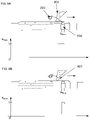
- FIGS. 1 and 2 A particle layer is applied to a building platform ( 102 ), which is provided in a build container ( 104 ).
- this building platform ( 102 ) and its movement define the shape and geometry of the layer. Layers having exactly parallel bases and cover surfaces ( 204 ) are usually desirable. Building platform ( 102 ) is therefore precisely guided, and its movement defines the layer thickness.
- This volume ( 206 ) is filled with powder by the so-called coater ( 202 ).
- a large amount of powder is usually provided at the start position of the coating pass and spread out into layer volume ( 206 ) by blade ( 205 ) or a rotating roller.
- the powder may also be delivered during the coating operation.
- the quantity of powder may also be stored ( 201 ), for example, in the coater itself.
- the coater begins to dispense powder in the direction of travel at the beginning of the build space. Powder is continuously dispensed during the coating pass to compensate for the loss due to the filling of the layer or at least to ensure that sufficient material remains for filling at the end of the coating pass. Overfeed powder present at the end of the coating pass may be pushed past the edge of the build space and allowed to fall there ( 209 ).
- the quantity of powder in front of the coater should not be unnecessarily large. Too large a quantity of powder is harmful to the layering process in two respects. On the one hand, a large quantity in front of the coater results in comparatively high forces on the emerging components in the powder. This may cause deformations. On the other hand, a large overfeed at the end of the coating pass is undesirable, since the material actually unused may be fed back to the process only after complex sieving. There is a high probability that this powder contains contaminants such as component fragments or traces of binding agent
- the flow of powder of the exemplary coating system with “inner storage” is switched by vibrations with the aid of an eccentric drive ( 203 ).
- the coater itself is designed as an elongated silo, which has a narrow opening on its lower end in the coating direction.
- the powder is unable to leave the narrow gap without vibrations, since bridges made of the particles form, or the powder flows out in a longitudinal gap ( 601 ). Either the bridges are broken or the material angle of repose is changed by the energy of the vibrations. The material flows out.
- the outflow is limited by the quantity that forms the overfeed of the filling in front of the coater. A self-regulating principle is thus implemented.
- a coater ( 202 ), driven via an eccentric ( 203 ), as illustrated in the example, is particularly suitable for a regulation.
- the upper limit of the powder quantity is regulated by the mechanism described.
- the lower limit may be easily observed by evaluating the overfeed.
- the coater pushes overfeed ( 200 ) onward to a waste shaft ( 208 ) downstream from the build space, so that the powder does not disturb the rest of the build process.
- the part of the device downstream from the build space is usually covered by a thin quantity of powder ( 207 ), which is built up by the overfeed before the actual build process begins, like on the building platform.
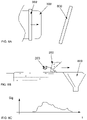
- FIG. 4 shows a diagram that represents the mass flow from the coater at a point in time.
- the figure shows an example of the defect status of the coater which is to be detected by the method. It is apparent how blockages in the powder gap influence the outflow quantity.
- FIG. 5 shows a specific embodiment, in which overfeed ( 200 ) falls over the edge of build space ( 209 ) and then lands in the bowl of a weighing device ( 500 ), whereby overfeed ( 200 ) may be measured by weighing. After weighing, bowl ( 500 ) may be automatically emptied with the aid of a pivot joint ( 501 ).
- capacitive sensors ( 600 ) are disposed upstream from waste shaft ( 208 ).
- One or multiple sensors is/are installed, depending on the desired resolution. They are adjusted in such a way that they do not detect the thin powder layer situated above them, which does not change during the build process. However, if an additional quantity of powder passes over sensors ( 600 ), they emit a signal.
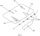
- FIG. 7 shows the arrangement of the sensors relative to the build space. This may take place by precisely determining the position and matching it to the signal over time.
- the controller may likewise be designed in such a way that the coater with the overfeed stops at the height of the sensors and is moved backward a short distance, so that the sensor signal is not influenced. The measurement is thus no longer time-critical, and the requirements imposed on the evaluation are much less strict.
- multiple sensors ( 600 ) are installed in the exemplary device in a line in parallel to the coater.
- the coater is to be able to cover a build space width of 550 mm, and the sensors are distributed evenly over this length.
- defects having a dimension of approximately 50 mm may be reliably detected at the end of the build space.
- FIGS. 8A, 8B, and 8C illustrates another option for achieving a spatial resolution.
- the build space is illustrated from above, including the coater and a rotated powder waste shaft.
- the waste powder flow is collected in a hopper.
- the overfeed powder would fall little by little into the hopper when it passes over the waste shaft, and thus results in a way to detect the local powder outflow quantity.
- FIG. 8C shows an example of a signal. It illustrates an outflow behavior in which less powder exits at the edges of the coater.
- five sensors are evaluated as follows: If one of the sensors does not supply a signal, the vibration is intensified during the generation of the next layer of the build process, in this case via the rotational speed of eccentric excitation means ( 203 ). If all sensors supply signals, the rotational speed is reduced for the next layer. This maintains the coating operation for the build process in a nearly optimum corridor.
- Coater ( 202 ) itself is designed as an elongated silo, which has a narrow opening on its lower end in the coating direction.
- the powder is unable to leave the narrow gap without vibrations, since bridges made of the particles form, or the powder flows out in a longitudinal gap ( 601 ). Either the bridges are broken or the material angle of repose is changed by the energy of the vibrations. The material flows out.
- Typical rotational speeds for the vibration excitation in the arrangement described above are around 3,000 rpm.
- the regulation adjusts the rotational speed of the coating by discrete values for each layer—the rotational speed is discretely reduced or increased, depending on the sensor result.
- the rotational speed is preferably adjusted in increments of 10 rpm. Increments of 50 rpm are even more preferable. Rapid changes in powder qualities may also be processed at 300 rpm—although the defect susceptibility continues to increase. In principle, there is no limit to the increment sizes in the rotational speed range of 0 to 6,000 rpm.
- the regulation may also act upon other parameters, for example if the powder dispensing quantity is not controlled via the rotational speed.
- the lift of a storage cylinder may be adapted. The lift is increased or reduced, depending on the sensor result.
- the device described may also be used only for monitoring the process.
- the signal of sensors ( 600 ) is logged layer by layer for this purpose. This approach may be desirable when the parameters, which may be adjusted, influence, for example, the component properties, and this is unacceptable.
- the information may be additionally used to display a warning to the machine operator.
- the printing of the build space using a print head ( 100 ) follows the coating pass. This may be followed by additional steps, depending on the process. After they are carried out, building platform ( 102 ) is moved and brought into a position which makes it possible to generate the next layer with the aid of the coater. The parameters which were changed by the regulation are used for this next coating pass. The coating pass is again evaluated by the regulating mechanism.
- Components ( 103 ) are completed by continuously repeating this sequence.
Landscapes
- Chemical & Material Sciences (AREA)
- Engineering & Computer Science (AREA)
- Materials Engineering (AREA)
- Manufacturing & Machinery (AREA)
- Physics & Mathematics (AREA)
- Optics & Photonics (AREA)
- Mechanical Engineering (AREA)
- Analytical Chemistry (AREA)
- Automation & Control Theory (AREA)
Abstract
Description
- The present application is a divisional application of U.S. patent application 15/364,613, filed on Nov. 30, 2016 which claims priority to German Patent Application DE 10 2015 015 353.6 filed on Dec. 1, 2015, by Ederer et al. The contents of U.S. patent application 15/364,613 and German Patent Application DE 10 2015 015 353.6 are each incorporated herein by reference in its entirety.
- The present invention relates to a method for producing three-dimensional components, amorphous particulate material being applied in layers to a build space, particulate material being placed on a build space in front of a scraper apparatus and then spread out, and the particulate material being subsequently solidified.
- The invention furthermore relates to a device for producing three-dimensional components, comprising a coating device which includes a scraper apparatus and comprising a selective solidification apparatus.
- A method for producing three-dimensional objects from computer data is described in the European patent specification EP 0 431 924 B1. In this method, a particulate material is applied in a thin layer to a platform with the aid of a coater, and a binder material is selectively printed onto this particulate material, using a print head. The particle area onto which the binder is printed is bound and solidifies under the influence of the binder and possible an additional hardener. The building platform is then lowered by the thickness of one layer, or the coater/print head unit is raised, and a new layer of particulate material is applied, which is also selectively printed upon as described above. These steps are repeated until the desired height of the object is reached. A three-dimensional object (molded part) is thus produced from the printed and solidified areas.
- After it is completed, this object produced from solidified particulate material is embedded in loose particulate material and is subsequently removed therefrom. This is done, for example, using an extractor. This leaves the desired objects, from which powder deposits are removed, for example by manual brushing.
- Of the layering techniques, 3D printing based on powdered materials and the supply of liquids with the aid of a print head is the fastest method.
- This method may be used to process different fluids, such as particulate materials, including natural biological raw materials, polymers, metals, ceramics and sands (not an exhaustive list).
- In addition, other methods exist, such as the fused deposition modeling (FDM) layering method, in which the cross sections of the component are built up by a liquid medium which solidifies outside a nozzle, the position of the building platform is changed from the last position by one layer thickness, and these steps are be repeated until the component is finished.
- All these methods are referred to collectively below as “layering methods,” “three-dimensional printing methods” or 3D printing methods.
- Other powder-supported rapid prototyping processes work in a similar manner, for example selective laser sintering or electron beam sintering, in which a loose particulate material is also deposited in layers and selectively solidified with the aid of a controlled physical radiation source. The material is thus solidified by high-energy radiation. In conventional production systems, the components are frequently produced in layers vertically from top to bottom.
- In 3D printing using the binder jetting technique, powders are the basis for the process. They are repeatedly applied in thin layers onto a building platform and printed with binder. The building platform is lowered for each new layer. Similarly, the coater plane may be raised, or the building platform may be designed as a conveyor belt.
- The material may be provided, for example, in a silo and transferred to the production machine with the aid of screw conveyors. The binder is introduced by manually inserting binder-filled canisters, and the build container may be set up by means of rails or simply using a transport frame. In doing so, the spatial directions of all movements cross each other. In many cases, movements in individual operations are possible in multiple or all spatial directions.
- In the layering process of the aforementioned methods, powder is placed, for example, in front of a scraper apparatus, spread out over the build space and smoothed. Various devices are used for this purpose. On the one hand, the powder may be provided upstream from the beginning of the build space. Slides that place a quantity of powder in the active area of the scraper apparatus are suitable for this purpose. On the other hand, powder may be continuously delivered in front of the scraper apparatus during the coating process.
- All methods generate an overfeed, which accumulates up to the end of the coating path and/or is depleted from the original volume, depending on the method and setting. In this specification, this quantity is referred to as overfeed (overflow quantity). The overfeed is the quantity of powder that is pushed in front of the coater at the end of the build space during the coating pass.
- If no overfeed occurs at the end of the coating path, the layer has not been completely filled to a relatively great degree of certainty. The presence of the overfeed at the end of the coating path is an indication that too much powder is being processed but the layer has been completely filled.
- The object of this invention, therefore, is to provide a method and a device which use this knowledge to document a reliable process flow and also to regulate it according to one preferred specific embodiment.
- This object is achieved by a method and a device according to the teachings herein.
- In one aspect, disclosed is a method for producing three-dimensional components, amorphous particulate material being applied in layers to a build space in a receiving plane, particulate material being placed on a build space in front of a scraper apparatus and then spread out, and the particulate material subsequently being selectively solidified. A measurement of an overfeed of particulate material is carried out.
- In another aspect, the disclosure relates to a device for producing three-dimensional components, comprising a coating device which includes a scraper apparatus and comprising a selective solidification apparatus, at least one sensor for measuring an overfeed of particulate material being provided downstream from the coating device in the coating direction.
- These aspects of the disclosure may be further characterized by one or any combination of the features disclosed herein. For example, these aspects of the disclosure may be further characterized by one or any combination of the following features: the measurement takes place during a coating pass; the measurement takes place at the end of a coating pass; the measurement takes place locally resolved; the measurement takes place over an entire coater width; a supply of particulate material is controlled directly by the measurement; the sensor is provided at the end of a coating path; one or more sensors are binary; one or more sensors are digital; one or more sensors are analog; one or more sensors are/or chromatographic sensors; a particulate material supply means is provided for supplying particulate material to a build space (preferably during a coating pass); or the particulate material supply means is controllable by the one or more sensors.
-
FIG. 1 : shows a sectional view of a device for producing three-dimensional components by means of the binder jetting technique. -
FIG. 2 : shows an illustration of the overfeed during the coating operation, different positions of the coater being shown inFIG. 2A ,FIG. 2B , andFIG. 2C . -
FIG. 3 : shows an illustration of a propagation of coating defects during the coating operation. -
FIG. 4 : shows a resulting overfeed over the length of the coater during the coating operation fromFIG. 3 . -
FIG. 5 : shows a representation of a device for determining the overfeed quantity with the aid of a weighing device. -
FIGS. 6A and 6B : shows a representation of a binary method for determining the presence of overfeed with the aid of a sensor. InFIG. 6A , material is flowing out of the coater (202) and inFIG. 6B , the coater (202) is clogged (601). -
FIG. 7 : shows a representation of an expanded, locally resolved determination of the overfeed. -
FIGS. 8A, 8B, and 8C : shows a representation of an implementation of the spatial overfeed distribution in a time signal with the aid of a light barrier.FIG. 8A is an top view showing illustrative features of a build space.FIG. 8B is an cross-sectional side view showing illustrative features of a waste shaft.FIG. 8C is a chart showing an illustrative signal. - A number of terms are defined in greater detail below. Otherwise, the meanings known to those skilled in the art are to be understood for the terms used.
- Within the meaning of the invention, “layering method” and “3D printing method” are all methods known from the prior art which facilitate the construction of components in three-dimensional molds and are compatible with the described process components and devices.
- “Molded body” or “component” within the meaning of the invention are all three-dimensional objects that are produced with the aid of the method according to the invention and/or the device according to the invention and which have a nondeformability.
- “Build space” is the plane or, in the broader sense, the geometric place on or in which the particulate material feedstock grows during the build process, due to repeated coating with particulate material. The build space is frequently delimited by a base, the “building platform,” by walls and an open cover surface, the build plane.
- According to the present description, a “reception plane” is understood to be the plane to which the build material is applied. It does not necessarily have to be a straight surface but may also have a curvature. This plane also does not absolutely have to correspond to a platform or conveyor belt plane. Instead, the reception plane may also be, for example, a material cone side of the build material.
- According to the present invention, “spread out” means any way in which the particulate material is distributed. For example, a large amount of powder may be provided at the start position of a coating pass and be distributed into the layer volume or spread out by a blade or a rotating roller.
- All free-flowing materials known for 3D printing may be used as “particulate material,” in particular in powdered form, as slag or as a liquid. This may be, for example, sands, ceramic powders, glass powders and other powders made of inorganic materials, metal powders, plastics, wood particles, fibrous materials, celluloses and/or lactose powders as well as other types of organic, powdered materials. The particulate material is preferably a dry, free-flowing powder, although a cohesive, firm powder may also be used. This cohesiveness may also result from the admixture of a binder material or an auxiliary material.
- The “overflow quantity” or “overfeed” is the quantity of particulate material that is pushed in front of the coater at the end of the build space during the coating pass.
- Any known 3D printing device for layering that contains the necessary components may be used as the “device” for carrying out the method according to the invention. Common components include a coater, a build space, a means for moving the build space or other components, a dosing device and a heating means and other components which are known to those skilled in the art and therefore do not need to be listed in greater detail here.
- A “coater” or “recoater” is the unit by means of which the particulate material is applied to or onto the build space. It may comprise a fluid storage container and a fluid application unit, the fluid application unit, according to the present invention, including a fluid outlet and a “scraper apparatus.” This scraper apparatus could be a coater blade. However, any other conceivable, suitable scraper apparatus could also be used. For example, rotating rollers are conceivable.
- A “selective solidification apparatus” may be, for example, a radiation source which solidifies the particulate material by supplying radiation. However, it may also be a print head which selectively applies the binder material and/or activator material or the like to the particulate material.
- The “print head” is usually assembled from different components. These are the print modules, among other things. They are oriented relative to the print head. The print head is oriented relative to the machine. As a result, the location of a nozzle may be assigned to the machine coordinate system.
- “Binder jetting layering” is understood to mean that powder is applied in layers onto a building platform, a liquid binder is printed onto the cross sections of the component on this powder layer, the position of the building platform is changed from the last position by one layer thickness, and these steps are repeated until the component is finished.
- “Laser sintering layering” is understood to mean that powder is applied in layers onto a building platform, the cross sections of the component on this powder layer are melted with the aid of a laser beam and solidified by cooling, the position of the building platform is changed from the last position by one layer thickness, and these steps are repeated until the component is finished.
- In “stereo lithography layering,” the cross sections of the component are solidified by a laser beam in a container having a liquid, by means of a chemical reaction. The position of the building platform is changed from the last position by one layer thickness, and these steps are repeated until the component is finished.
- Different aspects of the invention are described below.
- In one aspect, the invention relates to a method for producing three-dimensional components, amorphous particulate material being applied in layers to a build space in a receiving plane, particulate material being placed on a build space in front of a scraper apparatus and then spread out, and the particulate material subsequently being selectively solidified. A measurement of an overfeed of particulate material is then carried out.
- Common to all layering methods is that they have an overflow quantity of particulate material, which collects up to the end of the coating path and/or is depleted from the original volume, depending on the method and setting. This quantity is also referred to as overfeed. The overfeed is the quantity of powder that is pushed in front of the coater at the end of the build field during the coating pass.
- If no overfeed occurs at the end of the coating path, it can usually be assumed that the layer has not been completely filled. The presence of the overfeed at the end of the coating path is an indication that too much powder is being processed, but the layer has been completely filled.
- The present invention uses this property to document a secure process flow with regard to the particulate material coating.
- According to one preferred specific embodiment of the invention, the method is carried out in such a way that the measurement of the overfeed takes place at the end of and/or during a coating pass.
- According to one particularly preferred specific embodiment of the present invention, in the method, the measurement of the overfeed is locally resolved and is preferably carried out over an entire coater width.
- This may take place using different methods. For example, multiple sensors may be disposed a short distance downstream from the build space in the width of the coater, and its signals may be distinctively evaluated. It is also conceivable to use a quasi-analog, locally resolved sensor. This analog signal must then be analyzed in terms of time. The overfeed, as described in this specification, may also be time-resolved by a special design of the device.
- In a method of this type, it is now possible to obtain information, locally resolved, transversely to the coating direction. However, it should be noted here that this resolution is limited by the running together of the powder, due to the method.
- Process defects, as used in the present case, are sites which are not filled with particulate material after the passage of the coater. Tests have shown that serious process defects begin on the build space and usually spread in the direction of the end of the coating path. A resolution which is relevant to the particular system may thus be determined. The density of the sensing elements may be determined or the evaluation method assessed with the aid of this resolution.
- In a method according to the invention, the measurement of the particulate material distribution may also preferably take place during the coating pass, and a particulate material supply means may be controlled directly by the measurement.
- If a regulation is to take place in addition to the measurement, a type of actuator should also be provided, which acts upon the powder quantity.
- According to another aspect, the invention also relates to a device for producing three-dimensional components, comprising a coating device which includes a scraper apparatus and comprising a selective solidification apparatus. At least one sensor for measuring an overfeed of particulate material is provided downstream from the coating device in the coating direction.
- If the sensor is provided at the end of a coating path, according to one preferred specific embodiment, whether an overfeed is or is not present may be measured at the end. As was already described above, coating defects spread over the application path and are thus also detectable at the end of the coating pass.
- The sensors for measuring the overfeed may be binary, digital, analog and/or chromatographic sensors.
- In principle, all sensors suitable for detecting the presence of powder may be used. Optical sensors, capacitive sensors as well as load cells are examples thereof.
- All sensors should be disposed in such a way that they reliable detect the overfeed powder, and the same conditions again prevail layer by layer. To achieve the second effect, passive or active designs may be used. A passive design could be, for example, a powder waste shaft, into which the overfeed powder falls and is detected while falling.
- The powder may likewise be first pushed to a measuring point and then into a waste shaft by the coater. This movement may also run in an integrated, continuous manner. In an active device, within the meaning of this invention, the status is forcibly reestablished by an add-on element. One example thereof could be a flap, on which the overfeed powder is sensed and subsequently flipped into a waste container.
- A binary sensor within the meaning of the invention only determines whether overfeed powder is or is not present after the coating process. An arrangement of this type may be achieved, for example, with the aid of an initiator which is disposed downstream from the build space, beneath the coater plane. Its sensitive surface must be disposed in the direction of the overfeed powder. Optical and capacitive sensors, for example, are suitable.
- An arrangement of this type is suitable only for detecting very serious faults in the coating operation. A defect location may not be made out.
- A similar effect may be achieved by arranging multiple sensors downstream from the build space, transversely to the coating direction. Due to the increased resolution, this “digital sensor” is much more suitable for monitoring the coating operation. Much smaller defects may be detected with the aid of this arrangement, and the quantity of sensors may be adapted to the process conditions. The signal is locally resolved in this method.
- If the overfeed powder is detected by an analog measuring apparatus, this may further improve the monitoring of the coating operation. A sensor of this type may be a weighing apparatus. The signal may quantitatively reflect the seriousness of the fault. A local resolution is not possible.
- If the waste shaft is disposed at an angle to the coater and combines the powder in the waste shaft with the aid of an adjuster, conclusions may be drawn about the location of the fault by measuring the powder throughput over time. A large number of methods are suitable for this measurement. For example, light barriers as well as load cells may be used.
- According to one preferred specific embodiment, in a device according to the invention, a particulate material supply means is provided for supplying particulate material to a build space during a coating pass.
- If a regulation is to additionally take place, a type of actuator should also be provided, which acts upon the powder quantity.
- Such a control of the particulate material supply means is controllable, for example, with the aid of sensors.
- The present invention is explained in greater detail below on the basis of examples which illustrate the preferred specific embodiments.
- The basic device for applying the invention is a device used in production in the sense of additive manufacturing. Powder-based methods are essential in this case.
- In powder-based methods, a thin layer of powder must be generated as the basis for the process. Examples thereof are illustrated in
FIGS. 1 and 2 . A particle layer is applied to a building platform (102), which is provided in a build container (104). In the method according to the prior art, this building platform (102) and its movement define the shape and geometry of the layer. Layers having exactly parallel bases and cover surfaces (204) are usually desirable. Building platform (102) is therefore precisely guided, and its movement defines the layer thickness. - This volume (206) is filled with powder by the so-called coater (202). A large amount of powder is usually provided at the start position of the coating pass and spread out into layer volume (206) by blade (205) or a rotating roller. However, the powder may also be delivered during the coating operation.
- The quantity of powder may also be stored (201), for example, in the coater itself. The coater begins to dispense powder in the direction of travel at the beginning of the build space. Powder is continuously dispensed during the coating pass to compensate for the loss due to the filling of the layer or at least to ensure that sufficient material remains for filling at the end of the coating pass. Overfeed powder present at the end of the coating pass may be pushed past the edge of the build space and allowed to fall there (209).
- The quantity of powder in front of the coater should not be unnecessarily large. Too large a quantity of powder is harmful to the layering process in two respects. On the one hand, a large quantity in front of the coater results in comparatively high forces on the emerging components in the powder. This may cause deformations. On the other hand, a large overfeed at the end of the coating pass is undesirable, since the material actually unused may be fed back to the process only after complex sieving. There is a high probability that this powder contains contaminants such as component fragments or traces of binding agent
- The flow of powder of the exemplary coating system with “inner storage” is switched by vibrations with the aid of an eccentric drive (203). The coater itself is designed as an elongated silo, which has a narrow opening on its lower end in the coating direction. The powder is unable to leave the narrow gap without vibrations, since bridges made of the particles form, or the powder flows out in a longitudinal gap (601). Either the bridges are broken or the material angle of repose is changed by the energy of the vibrations. The material flows out.
- In this exemplary system, the outflow is limited by the quantity that forms the overfeed of the filling in front of the coater. A self-regulating principle is thus implemented.
- Tests have shown that defects in the coating process are usually caused by insufficient reflowing of powder into volume (206) to be filled. Since these defects continue to develop during the coating pass, frequent and less frequent defect patterns occur (see
FIG. 3 ). Defects that close again at the beginning of coating pass (302) are extremely rare. Local faults (301) in build space (300) without spreading to the rear likewise do not occur. The most frequent defects (303) start in the middle of build space (300) and increase in intensity up to the end of the coating path. An absence of the overfeed may therefore characterize faults in the coating operation very well. If a reaction does not occur, furrows (304) form, which become deeper layer by layer and divide the components. - A coater (202), driven via an eccentric (203), as illustrated in the example, is particularly suitable for a regulation. The upper limit of the powder quantity is regulated by the mechanism described. The lower limit may be easily observed by evaluating the overfeed.
- In devices according to the prior art, the coater pushes overfeed (200) onward to a waste shaft (208) downstream from the build space, so that the powder does not disturb the rest of the build process. The part of the device downstream from the build space is usually covered by a thin quantity of powder (207), which is built up by the overfeed before the actual build process begins, like on the building platform.
-
FIG. 4 shows a diagram that represents the mass flow from the coater at a point in time. In the form of a diagram, the figure shows an example of the defect status of the coater which is to be detected by the method. It is apparent how blockages in the powder gap influence the outflow quantity. -
FIG. 5 shows a specific embodiment, in which overfeed (200) falls over the edge of build space (209) and then lands in the bowl of a weighing device (500), whereby overfeed (200) may be measured by weighing. After weighing, bowl (500) may be automatically emptied with the aid of a pivot joint (501). - In the example illustrated in
FIG. 6A andFIG. 6B , capacitive sensors (600) are disposed upstream from waste shaft (208). One or multiple sensors is/are installed, depending on the desired resolution. They are adjusted in such a way that they do not detect the thin powder layer situated above them, which does not change during the build process. However, if an additional quantity of powder passes over sensors (600), they emit a signal. - The controller must ensure that the signals of the overfeed quantity and the coater body or the blade are differentiated.
FIG. 7 shows the arrangement of the sensors relative to the build space. This may take place by precisely determining the position and matching it to the signal over time. The controller may likewise be designed in such a way that the coater with the overfeed stops at the height of the sensors and is moved backward a short distance, so that the sensor signal is not influenced. The measurement is thus no longer time-critical, and the requirements imposed on the evaluation are much less strict. - To achieve a spatial resolution of the information, multiple sensors (600) are installed in the exemplary device in a line in parallel to the coater. In this example, the coater is to be able to cover a build space width of 550 mm, and the sensors are distributed evenly over this length. As a result, defects having a dimension of approximately 50 mm may be reliably detected at the end of the build space.
-
FIGS. 8A, 8B, and 8C illustrates another option for achieving a spatial resolution. In the top view (FIG. 8A ) the build space is illustrated from above, including the coater and a rotated powder waste shaft. As is apparent in the side view (FIG. 8B ), the waste powder flow is collected in a hopper. As a result, the overfeed powder would fall little by little into the hopper when it passes over the waste shaft, and thus results in a way to detect the local powder outflow quantity.FIG. 8C shows an example of a signal. It illustrates an outflow behavior in which less powder exits at the edges of the coater. - In this arrangement, five sensors are evaluated as follows: If one of the sensors does not supply a signal, the vibration is intensified during the generation of the next layer of the build process, in this case via the rotational speed of eccentric excitation means (203). If all sensors supply signals, the rotational speed is reduced for the next layer. This maintains the coating operation for the build process in a nearly optimum corridor.
- Coater (202) itself is designed as an elongated silo, which has a narrow opening on its lower end in the coating direction. The powder is unable to leave the narrow gap without vibrations, since bridges made of the particles form, or the powder flows out in a longitudinal gap (601). Either the bridges are broken or the material angle of repose is changed by the energy of the vibrations. The material flows out.
- Typical rotational speeds for the vibration excitation in the arrangement described above are around 3,000 rpm. The regulation adjusts the rotational speed of the coating by discrete values for each layer—the rotational speed is discretely reduced or increased, depending on the sensor result. The rotational speed is preferably adjusted in increments of 10 rpm. Increments of 50 rpm are even more preferable. Rapid changes in powder qualities may also be processed at 300 rpm—although the defect susceptibility continues to increase. In principle, there is no limit to the increment sizes in the rotational speed range of 0 to 6,000 rpm.
- The regulation may also act upon other parameters, for example if the powder dispensing quantity is not controlled via the rotational speed. For example, the lift of a storage cylinder may be adapted. The lift is increased or reduced, depending on the sensor result.
- The device described may also be used only for monitoring the process. The signal of sensors (600) is logged layer by layer for this purpose. This approach may be desirable when the parameters, which may be adjusted, influence, for example, the component properties, and this is unacceptable. The information may be additionally used to display a warning to the machine operator.
- In the process flow of the machine, the printing of the build space using a print head (100) follows the coating pass. This may be followed by additional steps, depending on the process. After they are carried out, building platform (102) is moved and brought into a position which makes it possible to generate the next layer with the aid of the coater. The parameters which were changed by the regulation are used for this next coating pass. The coating pass is again evaluated by the regulating mechanism.
- Components (103) are completed by continuously repeating this sequence.
-
- 100 Print head
- 102 Building platform
- 103 Component
- 104 Build container
- 200 Overfeed
- 201 Powder stock
- 202 Coater
- 203 Eccentric vibration drive
- 204 Cover layer/build space
- 205 Leveling blade
- 206 As yet unfilled layer area
- 207 Leveled powder outside the build space
- 208 Powder waste shaft
- 209 Falling overfeed powder
- 300 Build space
- 301 Inner coating defect
- 302 Coating defect at the coating pass starting point
- 303 Coating defect at the end of the build space
- 304 Deep coating defect
- 500 Bowl of a weighing apparatus
- 501 Pivot joint for automated emptying
- 600 Sensor for detecting powder
- 601 Clogged powder outflow
- 800 Rotated powder waste shaft
Claims (21)
Priority Applications (1)
| Application Number | Priority Date | Filing Date | Title |
|---|---|---|---|
| US17/553,944 US12036732B2 (en) | 2015-12-01 | 2021-12-17 | Method and device for producing three- dimensional components with the aid of an overfeed sensor |
Applications Claiming Priority (4)
| Application Number | Priority Date | Filing Date | Title |
|---|---|---|---|
| DE102015015353.6 | 2015-12-01 | ||
| DE102015015353.6A DE102015015353A1 (en) | 2015-12-01 | 2015-12-01 | Method and device for producing three-dimensional components by means of an excess quantity sensor |
| US15/364,613 US11235518B2 (en) | 2015-12-01 | 2016-11-30 | Method and device for producing three-dimensional components with the aid of an overfeed sensor |
| US17/553,944 US12036732B2 (en) | 2015-12-01 | 2021-12-17 | Method and device for producing three- dimensional components with the aid of an overfeed sensor |
Related Parent Applications (1)
| Application Number | Title | Priority Date | Filing Date |
|---|---|---|---|
| US15/364,613 Division US11235518B2 (en) | 2015-12-01 | 2016-11-30 | Method and device for producing three-dimensional components with the aid of an overfeed sensor |
Publications (2)
| Publication Number | Publication Date |
|---|---|
| US20220184886A1 true US20220184886A1 (en) | 2022-06-16 |
| US12036732B2 US12036732B2 (en) | 2024-07-16 |
Family
ID=57406099
Family Applications (2)
| Application Number | Title | Priority Date | Filing Date |
|---|---|---|---|
| US15/364,613 Expired - Fee Related US11235518B2 (en) | 2015-12-01 | 2016-11-30 | Method and device for producing three-dimensional components with the aid of an overfeed sensor |
| US17/553,944 Active US12036732B2 (en) | 2015-12-01 | 2021-12-17 | Method and device for producing three- dimensional components with the aid of an overfeed sensor |
Family Applications Before (1)
| Application Number | Title | Priority Date | Filing Date |
|---|---|---|---|
| US15/364,613 Expired - Fee Related US11235518B2 (en) | 2015-12-01 | 2016-11-30 | Method and device for producing three-dimensional components with the aid of an overfeed sensor |
Country Status (3)
| Country | Link |
|---|---|
| US (2) | US11235518B2 (en) |
| EP (1) | EP3181334B1 (en) |
| DE (1) | DE102015015353A1 (en) |
Cited By (1)
| Publication number | Priority date | Publication date | Assignee | Title |
|---|---|---|---|---|
| US20220016844A1 (en) * | 2019-04-30 | 2022-01-20 | Hewlett-Packard Development Company, L.P. | Build Material Spreading Apparatuses for Additive Manufacturing |
Families Citing this family (49)
| Publication number | Priority date | Publication date | Assignee | Title |
|---|---|---|---|---|
| US10226919B2 (en) | 2007-07-18 | 2019-03-12 | Voxeljet Ag | Articles and structures prepared by three-dimensional printing method |
| DE102007050953A1 (en) | 2007-10-23 | 2009-04-30 | Voxeljet Technology Gmbh | Device for the layered construction of models |
| DE102010014969A1 (en) | 2010-04-14 | 2011-10-20 | Voxeljet Technology Gmbh | Device for producing three-dimensional models |
| DE102011007957A1 (en) | 2011-01-05 | 2012-07-05 | Voxeljet Technology Gmbh | Device and method for constructing a layer body with at least one body limiting the construction field and adjustable in terms of its position |
| DE102011111498A1 (en) | 2011-08-31 | 2013-02-28 | Voxeljet Technology Gmbh | Device for the layered construction of models |
| DE102012004213A1 (en) | 2012-03-06 | 2013-09-12 | Voxeljet Technology Gmbh | Method and device for producing three-dimensional models |
| DE102012010272A1 (en) | 2012-05-25 | 2013-11-28 | Voxeljet Technology Gmbh | Method for producing three-dimensional models with special construction platforms and drive systems |
| DE102012012363A1 (en) | 2012-06-22 | 2013-12-24 | Voxeljet Technology Gmbh | Apparatus for building up a layer body with a storage or filling container movable along the discharge container |
| DE102012020000A1 (en) | 2012-10-12 | 2014-04-17 | Voxeljet Ag | 3D multi-stage process |
| DE102013004940A1 (en) | 2012-10-15 | 2014-04-17 | Voxeljet Ag | Method and device for producing three-dimensional models with tempered printhead |
| DE102013003303A1 (en) | 2013-02-28 | 2014-08-28 | FluidSolids AG | Process for producing a molded part with a water-soluble casting mold and material system for its production |
| DE102013018182A1 (en) | 2013-10-30 | 2015-04-30 | Voxeljet Ag | Method and device for producing three-dimensional models with binder system |
| DE102013018031A1 (en) | 2013-12-02 | 2015-06-03 | Voxeljet Ag | Swap body with movable side wall |
| DE102013020491A1 (en) | 2013-12-11 | 2015-06-11 | Voxeljet Ag | 3D infiltration process |
| DE102014004692A1 (en) | 2014-03-31 | 2015-10-15 | Voxeljet Ag | Method and apparatus for 3D printing with conditioned process control |
| DE102014007584A1 (en) | 2014-05-26 | 2015-11-26 | Voxeljet Ag | 3D reverse printing method and apparatus |
| WO2016019937A1 (en) | 2014-08-02 | 2016-02-11 | Voxeljet Ag | Method and casting mould, in particular for use in cold casting methods |
| DE102015006533A1 (en) | 2014-12-22 | 2016-06-23 | Voxeljet Ag | Method and device for producing 3D molded parts with layer construction technique |
| DE102015003372A1 (en) | 2015-03-17 | 2016-09-22 | Voxeljet Ag | Method and device for producing 3D molded parts with double recoater |
| DE102015006363A1 (en) | 2015-05-20 | 2016-12-15 | Voxeljet Ag | Phenolic resin method |
| DE102015011503A1 (en) | 2015-09-09 | 2017-03-09 | Voxeljet Ag | Method for applying fluids |
| DE102015011790A1 (en) | 2015-09-16 | 2017-03-16 | Voxeljet Ag | Device and method for producing three-dimensional molded parts |
| DE102015015353A1 (en) | 2015-12-01 | 2017-06-01 | Voxeljet Ag | Method and device for producing three-dimensional components by means of an excess quantity sensor |
| DE102015016464B4 (en) | 2015-12-21 | 2024-04-25 | Voxeljet Ag | Method and device for producing 3D molded parts |
| DE102016002777A1 (en) | 2016-03-09 | 2017-09-14 | Voxeljet Ag | Method and device for producing 3D molded parts with construction field tools |
| DE102016013610A1 (en) | 2016-11-15 | 2018-05-17 | Voxeljet Ag | Intra-head printhead maintenance station for powder bed-based 3D printing |
| DE102017006860A1 (en) | 2017-07-21 | 2019-01-24 | Voxeljet Ag | Method and device for producing 3D molded parts with spectrum converter |
| US11890807B1 (en) | 2017-08-31 | 2024-02-06 | Blue Origin, Llc | Systems and methods for controlling additive manufacturing processes |
| US11273495B2 (en) | 2017-10-02 | 2022-03-15 | General Electric Company | Modified frame and recoating system |
| EP3695922B1 (en) * | 2017-10-13 | 2024-04-24 | IHI Corporation | Additive manufacturing device comprising a powder feeding device |
| JP6458182B1 (en) * | 2018-03-19 | 2019-01-23 | 株式会社松浦機械製作所 | 3D modeling method |
| US11383449B2 (en) | 2018-03-29 | 2022-07-12 | Hewlett-Packard Development Company, L.P. | Determining excess build material |
| CN108421977A (en) * | 2018-05-03 | 2018-08-21 | 沙洲职业工学院 | A kind of intelligence increasing material manufacturing equipment |
| DE102018006473A1 (en) | 2018-08-16 | 2020-02-20 | Voxeljet Ag | Method and device for the production of 3D molded parts by means of layer construction technology by means of a closure device |
| CN109622956B (en) * | 2018-12-12 | 2020-12-08 | 吉林大学 | An anti-stick powder device for selective laser melting equipment |
| DE102019000796A1 (en) | 2019-02-05 | 2020-08-06 | Voxeljet Ag | Exchangeable process unit |
| US11819943B1 (en) | 2019-03-28 | 2023-11-21 | Blue Origin Llc | Laser material fusion under vacuum, and associated systems and methods |
| DE102019004176A1 (en) | 2019-06-14 | 2020-12-17 | Voxeljet Ag | Method and device for the production of 3D molded parts by means of layering technology and coater with vacuum seal |
| DE102019007073A1 (en) | 2019-10-11 | 2021-04-15 | Voxeljet Ag | Method and device for the production of 3D molded parts by means of high-performance radiators |
| DE102019007595A1 (en) | 2019-11-01 | 2021-05-06 | Voxeljet Ag | 3D PRINTING PROCESS AND MOLDED PART MANUFACTURED WITH LIGNINE SULPHATE |
| DE102019007863A1 (en) | 2019-11-13 | 2021-05-20 | Voxeljet Ag | Particulate matter preheater and use in 3D processes |
| AU2021273984B2 (en) * | 2020-05-22 | 2024-06-13 | William Marsh Rice University | Methods of fabricating laser-sintered carbohydrate materials and compositions and uses thereof |
| EP3943220A1 (en) * | 2020-07-24 | 2022-01-26 | Aixway3D GmbH | Device and method for a powder system for improved powder application efficiency in an additive manufacturing method |
| DE102020006886A1 (en) | 2020-11-10 | 2022-05-12 | Laempe Mössner Sinto Gmbh | Process for applying particulate building material in a 3D printer |
| DE102021106204A1 (en) | 2021-03-15 | 2022-09-15 | Trumpf Laser- Und Systemtechnik Gmbh | METHOD FOR MEASURING APPLICATION BEHAVIOR OF POWDER, METHOD FOR DETERMINING A LAYER INCREASE QUANTITY, METHOD FOR ADDITIONAL MANUFACTURING OF A COMPONENT LAYER AND DEVICE FOR ADDITIONAL MANUFACTURING |
| CN113020623B (en) * | 2021-05-27 | 2022-04-08 | 西安赛隆金属材料有限责任公司 | 3D printing forming surface self-adjusting method and device |
| DE102022000909A1 (en) | 2022-03-16 | 2023-09-21 | Laempe Mössner Sinto Gmbh | Arrangement and method for applying particulate building material in a 3D printer |
| DE102022111565A1 (en) | 2022-05-10 | 2023-11-16 | Trumpf Laser- Und Systemtechnik Gmbh | Method and device for powder quantity control |
| CN120079889B (en) * | 2025-05-07 | 2025-08-05 | 四川工程职业技术大学 | Variable-speed powder spreading device for laser selective melting forming and use method thereof |
Citations (6)
| Publication number | Priority date | Publication date | Assignee | Title |
|---|---|---|---|---|
| US20040265413A1 (en) * | 2003-05-23 | 2004-12-30 | Z Corporation | Apparatus and methods for 3D printing |
| US20130052291A1 (en) * | 2011-08-30 | 2013-02-28 | Sony Corporation | Powder removing apparatus, molding system, and method of manufacturing molded object |
| DE102011088158A1 (en) * | 2011-12-09 | 2013-06-13 | Bayerische Motoren Werke Aktiengesellschaft | Secondary circuit for device for producing three-dimensional metal object used in beam fusion plant, has return line that is provided for recycling of powder from overflow container in main circuit of device |
| US20160067929A1 (en) * | 2014-09-09 | 2016-03-10 | Ricoh Company, Ltd. | Apparatus for fabricating three-dimensional object |
| US20160349215A1 (en) * | 2014-12-23 | 2016-12-01 | Edison Welding Institute, Inc. | Non-destructive evaluation of additive manufacturing components using an eddy current array system and method |
| US20180194126A1 (en) * | 2015-06-19 | 2018-07-12 | Aconity Gmbh | Powder bed-based laser melting system |
Family Cites Families (337)
| Publication number | Priority date | Publication date | Assignee | Title |
|---|---|---|---|---|
| DE2261344C3 (en) | 1972-12-15 | 1979-05-31 | Karl Becker Kg Maschinenfabrik, 3525 Oberweser | Device for placing granular seeds in the ground in connection with precision seeders |
| US4247508B1 (en) | 1979-12-03 | 1996-10-01 | Dtm Corp | Molding process |
| US4591402A (en) | 1981-06-22 | 1986-05-27 | Ltv Aerospace And Defense Company | Apparatus and method for manufacturing composite structures |
| FR2511149A1 (en) | 1981-08-04 | 1983-02-11 | Roussel Uclaf | DEVICE AND METHOD FOR DETERMINING PREDETERMINED QUANTITIES OF AT LEAST ONE PRODUCT |
| US4711669A (en) | 1985-11-05 | 1987-12-08 | American Cyanamid Company | Method of manufacturing a bonded particulate article by reacting a hydrolyzed amylaceous product and a heterocyclic compound |
| DE3221357A1 (en) | 1982-06-05 | 1983-12-08 | Plasticonsult GmbH Beratungsgesellschaft für Kunststoff- und Oberflächentechnik, 6360 Friedberg | Process for the production of moulds and cores for casting purposes |
| JPS60180643A (en) | 1984-02-29 | 1985-09-14 | Nissan Motor Co Ltd | Collapsion assistant used for binder for molding sand |
| US4665492A (en) | 1984-07-02 | 1987-05-12 | Masters William E | Computer automated manufacturing process and system |
| US4575330A (en) | 1984-08-08 | 1986-03-11 | Uvp, Inc. | Apparatus for production of three-dimensional objects by stereolithography |
| JPS62275734A (en) | 1986-05-26 | 1987-11-30 | Tokieda Naomitsu | Method for forming solid |
| US5263130A (en) | 1986-06-03 | 1993-11-16 | Cubital Ltd. | Three dimensional modelling apparatus |
| IL84936A (en) | 1987-12-23 | 1997-02-18 | Cubital Ltd | Three-dimensional modelling apparatus |
| US4752352A (en) | 1986-06-06 | 1988-06-21 | Michael Feygin | Apparatus and method for forming an integral object from laminations |
| US5017753A (en) | 1986-10-17 | 1991-05-21 | Board Of Regents, The University Of Texas System | Method and apparatus for producing parts by selective sintering |
| US4944817A (en) | 1986-10-17 | 1990-07-31 | Board Of Regents, The University Of Texas System | Multiple material systems for selective beam sintering |
| KR960008015B1 (en) | 1986-10-17 | 1996-06-19 | 보드 오브 리젼츠, 디 유니버시티 오브 텍사스 시스템 | Method and apparatus for manufacturing parts by selective sintering |
| US5296062A (en) | 1986-10-17 | 1994-03-22 | The Board Of Regents, The University Of Texas System | Multiple material systems for selective beam sintering |
| US5155324A (en) | 1986-10-17 | 1992-10-13 | Deckard Carl R | Method for selective laser sintering with layerwise cross-scanning |
| US5076869A (en) | 1986-10-17 | 1991-12-31 | Board Of Regents, The University Of Texas System | Multiple material systems for selective beam sintering |
| US5147587A (en) | 1986-10-17 | 1992-09-15 | Board Of Regents, The University Of Texas System | Method of producing parts and molds using composite ceramic powders |
| US4863538A (en) | 1986-10-17 | 1989-09-05 | Board Of Regents, The University Of Texas System | Method and apparatus for producing parts by selective sintering |
| US4752498A (en) | 1987-03-02 | 1988-06-21 | Fudim Efrem V | Method and apparatus for production of three-dimensional objects by photosolidification |
| US5047182A (en) | 1987-11-25 | 1991-09-10 | Ceramics Process Systems Corporation | Complex ceramic and metallic shaped by low pressure forming and sublimative drying |
| US5772947A (en) | 1988-04-18 | 1998-06-30 | 3D Systems Inc | Stereolithographic curl reduction |
| CA1337955C (en) | 1988-09-26 | 1996-01-23 | Thomas A. Almquist | Recoating of stereolithographic layers |
| AU4504089A (en) | 1988-10-05 | 1990-05-01 | Michael Feygin | An improved apparatus and method for forming an integral object from laminations |
| US5637175A (en) | 1988-10-05 | 1997-06-10 | Helisys Corporation | Apparatus for forming an integral object from laminations |
| JP2738017B2 (en) | 1989-05-23 | 1998-04-08 | ブラザー工業株式会社 | 3D molding equipment |
| GB2233928B (en) | 1989-05-23 | 1992-12-23 | Brother Ind Ltd | Apparatus and method for forming three-dimensional article |
| US5248456A (en) | 1989-06-12 | 1993-09-28 | 3D Systems, Inc. | Method and apparatus for cleaning stereolithographically produced objects |
| US5216616A (en) | 1989-06-26 | 1993-06-01 | Masters William E | System and method for computer automated manufacture with reduced object shape distortion |
| US5134569A (en) | 1989-06-26 | 1992-07-28 | Masters William E | System and method for computer automated manufacturing using fluent material |
| JPH0336019A (en) | 1989-07-03 | 1991-02-15 | Brother Ind Ltd | Three-dimensional molding method and device |
| US5156697A (en) | 1989-09-05 | 1992-10-20 | Board Of Regents, The University Of Texas System | Selective laser sintering of parts by compound formation of precursor powders |
| US5053090A (en) | 1989-09-05 | 1991-10-01 | Board Of Regents, The University Of Texas System | Selective laser sintering with assisted powder handling |
| US5431967A (en) | 1989-09-05 | 1995-07-11 | Board Of Regents, The University Of Texas System | Selective laser sintering using nanocomposite materials |
| AU643700B2 (en) | 1989-09-05 | 1993-11-25 | University Of Texas System, The | Multiple material systems and assisted powder handling for selective beam sintering |
| US5182170A (en) | 1989-09-05 | 1993-01-26 | Board Of Regents, The University Of Texas System | Method of producing parts by selective beam interaction of powder with gas phase reactant |
| US5284695A (en) | 1989-09-05 | 1994-02-08 | Board Of Regents, The University Of Texas System | Method of producing high-temperature parts by way of low-temperature sintering |
| DE3930750A1 (en) | 1989-09-14 | 1991-03-28 | Krupp Medizintechnik | CASTING BEDS, EMBEDDING MODEL, CASTING MOLD AND METHOD FOR PREVENTING THE FLOWERING OF BEDROOMING MODELS AND CASTING MOLDS FROM A CASTING BEDS |
| US5136515A (en) | 1989-11-07 | 1992-08-04 | Richard Helinski | Method and means for constructing three-dimensional articles by particle deposition |
| US5204055A (en) | 1989-12-08 | 1993-04-20 | Massachusetts Institute Of Technology | Three-dimensional printing techniques |
| US5387380A (en) | 1989-12-08 | 1995-02-07 | Massachusetts Institute Of Technology | Three-dimensional printing techniques |
| DE3942859A1 (en) | 1989-12-23 | 1991-07-04 | Basf Ag | METHOD FOR PRODUCING COMPONENTS |
| GB9007199D0 (en) | 1990-03-30 | 1990-05-30 | Tioxide Group Plc | Preparation of polymeric particles |
| US5127037A (en) | 1990-08-15 | 1992-06-30 | Bynum David K | Apparatus for forming a three-dimensional reproduction of an object from laminations |
| US5126529A (en) | 1990-12-03 | 1992-06-30 | Weiss Lee E | Method and apparatus for fabrication of three-dimensional articles by thermal spray deposition |
| DE4102260A1 (en) | 1991-01-23 | 1992-07-30 | Artos Med Produkte | Apparatus for making shaped articles - has laser beam directed through transparent base of tank which contains laser-curable liquid and is sealed off by movable cover plate |
| US5740051A (en) | 1991-01-25 | 1998-04-14 | Sanders Prototypes, Inc. | 3-D model making |
| US5506607A (en) | 1991-01-25 | 1996-04-09 | Sanders Prototypes Inc. | 3-D model maker |
| US6175422B1 (en) | 1991-01-31 | 2001-01-16 | Texas Instruments Incorporated | Method and apparatus for the computer-controlled manufacture of three-dimensional objects from computer data |
| JP3104307B2 (en) | 1991-06-28 | 2000-10-30 | ソニー株式会社 | Plate material for gravure printing |
| US5252264A (en) | 1991-11-08 | 1993-10-12 | Dtm Corporation | Apparatus and method for producing parts with multi-directional powder delivery |
| US5269982A (en) | 1992-02-12 | 1993-12-14 | Brotz Gregory R | Process for manufacturing a shaped product |
| IT1254974B (en) | 1992-06-18 | 1995-10-11 | Bayer Italia Spa | COMPOSITE, SLIDING, HYDROPHOBIC GRANULATES, A PROCEDURE FOR THEIR PREPARATION AND THEIR USE |
| US5342919A (en) | 1992-11-23 | 1994-08-30 | Dtm Corporation | Sinterable semi-crystalline powder and near-fully dense article formed therewith |
| US5352405A (en) | 1992-12-18 | 1994-10-04 | Dtm Corporation | Thermal control of selective laser sintering via control of the laser scan |
| DE4300478C2 (en) | 1993-01-11 | 1998-05-20 | Eos Electro Optical Syst | Method and device for producing a three-dimensional object |
| US6146567A (en) | 1993-02-18 | 2000-11-14 | Massachusetts Institute Of Technology | Three dimensional printing methods |
| DE4305201C1 (en) | 1993-02-19 | 1994-04-07 | Eos Electro Optical Syst | Three dimensional component mfr with laser-cured resin and filler - involves mixing steel or ceramic powder in resin, laser curing given shape, heating in nitrogen@ atmosphere and nitric acid to remove resin and then sintering filler |
| US5433261A (en) | 1993-04-30 | 1995-07-18 | Lanxide Technology Company, Lp | Methods for fabricating shapes by use of organometallic, ceramic precursor binders |
| US5427722A (en) | 1993-06-11 | 1995-06-27 | General Motors Corporation | Pressure slip casting process for making hollow-shaped ceramics |
| DE4325573C2 (en) | 1993-07-30 | 1998-09-03 | Stephan Herrmann | Process for the production of moldings by successive build-up of powder layers and device for its implementation |
| US5398193B1 (en) | 1993-08-20 | 1997-09-16 | Alfredo O Deangelis | Method of three-dimensional rapid prototyping through controlled layerwise deposition/extraction and apparatus therefor |
| US5490962A (en) | 1993-10-18 | 1996-02-13 | Massachusetts Institute Of Technology | Preparation of medical devices by solid free-form fabrication methods |
| US5518680A (en) | 1993-10-18 | 1996-05-21 | Massachusetts Institute Of Technology | Tissue regeneration matrices by solid free form fabrication techniques |
| US5418112A (en) | 1993-11-10 | 1995-05-23 | W. R. Grace & Co.-Conn. | Photosensitive compositions useful in three-dimensional part-building and having improved photospeed |
| DE4400523C2 (en) | 1994-01-11 | 1996-07-11 | Eos Electro Optical Syst | Method and device for producing a three-dimensional object |
| US5518060A (en) | 1994-01-25 | 1996-05-21 | Brunswick Corporation | Method of producing polymeric patterns for use in evaporable foam casting |
| DE4440397C2 (en) | 1994-11-11 | 2001-04-26 | Eos Electro Optical Syst | Methods of making molds |
| JP3215881B2 (en) | 1994-05-27 | 2001-10-09 | イーオーエス ゲゼルシャフト ミット ベシュレンクテル ハフツング イレクトロ オプティカル システムズ | Methods used for casting technology |
| US5503785A (en) | 1994-06-02 | 1996-04-02 | Stratasys, Inc. | Process of support removal for fused deposition modeling |
| US6048954A (en) | 1994-07-22 | 2000-04-11 | The University Of Texas System Board Of Regents | Binder compositions for laser sintering processes |
| US5639402A (en) | 1994-08-08 | 1997-06-17 | Barlow; Joel W. | Method for fabricating artificial bone implant green parts |
| US5616631A (en) | 1994-08-17 | 1997-04-01 | Kao Corporation | Binder composition for mold making, binder/curing agent composition for mold making, sand composition for mold making, and process of making mold |
| JPH0889780A (en) * | 1994-09-22 | 1996-04-09 | Tokai Carbon Co Ltd | Granulating apparatus for powder and measuring method of particle size |
| US5555176A (en) | 1994-10-19 | 1996-09-10 | Bpm Technology, Inc. | Apparatus and method for making three-dimensional articles using bursts of droplets |
| US5717599A (en) | 1994-10-19 | 1998-02-10 | Bpm Technology, Inc. | Apparatus and method for dispensing build material to make a three-dimensional article |
| US5482659A (en) | 1994-12-22 | 1996-01-09 | United Technologies Corporation | Method of post processing stereolithographically produced objects |
| GB9501987D0 (en) | 1995-02-01 | 1995-03-22 | Butterworth Steven | Dissolved medium rendered resin (DMRR) processing |
| MX9705844A (en) | 1995-02-01 | 1997-11-29 | 3D Systems Inc | Rapid recoating of three-dimensional objects formed on a cross-sectional basis. |
| US5573721A (en) | 1995-02-16 | 1996-11-12 | Hercules Incorporated | Use of a support liquid to manufacture three-dimensional objects |
| DE19511772C2 (en) | 1995-03-30 | 1997-09-04 | Eos Electro Optical Syst | Device and method for producing a three-dimensional object |
| DE29506204U1 (en) | 1995-04-10 | 1995-06-01 | Eos Gmbh Electro Optical Systems, 82152 Planegg | Device for producing a three-dimensional object |
| DE19514740C1 (en) | 1995-04-21 | 1996-04-11 | Eos Electro Optical Syst | Appts. for producing three-dimensional objects by laser sintering |
| DE19515165C2 (en) | 1995-04-25 | 1997-03-06 | Eos Electro Optical Syst | Device for producing an object using stereolithography |
| DE19525307C2 (en) | 1995-07-12 | 2003-04-03 | Eichenauer Gmbh & Co Kg F | Molding compound for the production of casting cores and method for producing a casting core |
| DE19528215A1 (en) | 1995-08-01 | 1997-02-06 | Thomas Dipl Ing Himmer | Three=dimensional model or tool mfr. employing rapid prototyping methods - involves building up layers of different materials according to use and processing each layer by a variety of chemical, physical or mechanical methods |
| DE19530295C1 (en) | 1995-08-11 | 1997-01-30 | Eos Electro Optical Syst | Device for producing an object in layers by means of laser sintering |
| US5837960A (en) | 1995-08-14 | 1998-11-17 | The Regents Of The University Of California | Laser production of articles from powders |
| US5943235A (en) | 1995-09-27 | 1999-08-24 | 3D Systems, Inc. | Rapid prototyping system and method with support region data processing |
| US6270335B2 (en) | 1995-09-27 | 2001-08-07 | 3D Systems, Inc. | Selective deposition modeling method and apparatus for forming three-dimensional objects and supports |
| JPH11513328A (en) | 1995-09-27 | 1999-11-16 | スリーディー システムズ インコーポレーテッド | Method and apparatus for data manipulation and system control in selective additive manufacturing system |
| US6305769B1 (en) | 1995-09-27 | 2001-10-23 | 3D Systems, Inc. | Selective deposition modeling system and method |
| US5749041A (en) | 1995-10-13 | 1998-05-05 | Dtm Corporation | Method of forming three-dimensional articles using thermosetting materials |
| DE19545167A1 (en) | 1995-12-04 | 1997-06-05 | Bayerische Motoren Werke Ag | Method of manufacturing a prototype component or tool from a stereo-sintered polystyrene pattern |
| US5660621A (en) | 1995-12-29 | 1997-08-26 | Massachusetts Institute Of Technology | Binder composition for use in three dimensional printing |
| US6210625B1 (en) | 1996-02-20 | 2001-04-03 | Mikuni Corporation | Method for producing granulated material |
| DE69622592T2 (en) | 1996-03-06 | 2003-02-27 | Guild Associates, Inc. | DEVICE FOR PRODUCING A THREE-DIMENSIONAL BODY |
| US5747105A (en) | 1996-04-30 | 1998-05-05 | Owens Corning Fiberglas Technology Inc. | Traversing nozzle for applying granules to an asphalt coated sheet |
| US6596224B1 (en) | 1996-05-24 | 2003-07-22 | Massachusetts Institute Of Technology | Jetting layers of powder and the formation of fine powder beds thereby |
| GB9611582D0 (en) | 1996-06-04 | 1996-08-07 | Thin Film Technology Consultan | 3D printing and forming of structures |
| US6316060B1 (en) | 1996-08-20 | 2001-11-13 | Pacifica Papers Inc. | Metering coatings |
| US5902441A (en) | 1996-09-04 | 1999-05-11 | Z Corporation | Method of three dimensional printing |
| US7332537B2 (en) | 1996-09-04 | 2008-02-19 | Z Corporation | Three dimensional printing material system and method |
| JP3476633B2 (en) * | 1996-11-08 | 2003-12-10 | 愛三工業株式会社 | Powder feeder |
| US7037382B2 (en) | 1996-12-20 | 2006-05-02 | Z Corporation | Three-dimensional printer |
| US6007318A (en) | 1996-12-20 | 1999-12-28 | Z Corporation | Method and apparatus for prototyping a three-dimensional object |
| US6989115B2 (en) * | 1996-12-20 | 2006-01-24 | Z Corporation | Method and apparatus for prototyping a three-dimensional object |
| DE29701279U1 (en) | 1997-01-27 | 1997-05-22 | Eos Gmbh Electro Optical Systems, 82152 Planegg | Device with a process chamber and an element which can be moved back and forth in the process chamber |
| CA2288201A1 (en) | 1997-03-31 | 1998-10-08 | Therics, Inc. | Method for dispensing of powders |
| US5940674A (en) | 1997-04-09 | 1999-08-17 | Massachusetts Institute Of Technology | Three-dimensional product manufacture using masks |
| DE19715582B4 (en) | 1997-04-15 | 2009-02-12 | Ederer, Ingo, Dr. | Method and system for generating three-dimensional bodies from computer data |
| NL1006059C2 (en) | 1997-05-14 | 1998-11-17 | Geest Adrianus F Van Der | Method and device for manufacturing a shaped body. |
| US5997795A (en) | 1997-05-29 | 1999-12-07 | Rutgers, The State University | Processes for forming photonic bandgap structures |
| DE19723892C1 (en) | 1997-06-06 | 1998-09-03 | Rainer Hoechsmann | Method for producing components by build-up technology |
| DE19726778A1 (en) | 1997-06-24 | 1999-01-14 | Cerdec Ag | Process for the production of ceramic and glassy coatings, electrostatically applicable coating powder therefor and its use |
| DE69940582D1 (en) | 1998-01-29 | 2009-04-30 | Amino Corp | DEVICE FOR MANUFACTURING PLATE MATERIAL |
| DE19805437A1 (en) | 1998-02-11 | 1999-08-12 | Bosch Gmbh Robert | Dosing device for free-flowing bulk goods |
| US6355196B1 (en) | 1998-03-16 | 2002-03-12 | Vantico Inc. | Process for producing direct tooling mold and method for using the same |
| US5989476A (en) | 1998-06-12 | 1999-11-23 | 3D Systems, Inc. | Process of making a molded refractory article |
| JP3518726B2 (en) | 1998-07-13 | 2004-04-12 | トヨタ自動車株式会社 | Additive manufacturing method and resin-coated sand for additive manufacturing |
| US6476122B1 (en) | 1998-08-20 | 2002-11-05 | Vantico Inc. | Selective deposition modeling material |
| DE19846478C5 (en) | 1998-10-09 | 2004-10-14 | Eos Gmbh Electro Optical Systems | Laser-sintering machine |
| US20030114936A1 (en) | 1998-10-12 | 2003-06-19 | Therics, Inc. | Complex three-dimensional composite scaffold resistant to delimination |
| DE19853834A1 (en) | 1998-11-21 | 2000-05-31 | Ingo Ederer | Production of casting molds comprises depositing particulate material on support, applying binder and hardener to form solidified structure in selected region, and removing solidified structure |
| JP2000211918A (en) | 1999-01-20 | 2000-08-02 | Yazaki Corp | Manufacturing method of lightweight alumina particles |
| FR2790418B1 (en) | 1999-03-01 | 2001-05-11 | Optoform Sarl Procedes De Prot | RAPID PROTOTYPING PROCESS ALLOWING THE USE OF PASTY MATERIALS, AND DEVICE FOR IMPLEMENTING SAME |
| US6259962B1 (en) | 1999-03-01 | 2001-07-10 | Objet Geometries Ltd. | Apparatus and method for three dimensional model printing |
| DE19911399C2 (en) | 1999-03-15 | 2001-03-01 | Joachim Heinzl | Method for controlling a piezo print head and piezo print head controlled according to this method |
| US6485831B1 (en) | 1999-05-13 | 2002-11-26 | Shin-Etsu Chemical Co., Ltd. | Conductive powder and making process |
| US6405095B1 (en) | 1999-05-25 | 2002-06-11 | Nanotek Instruments, Inc. | Rapid prototyping and tooling system |
| US6165406A (en) | 1999-05-27 | 2000-12-26 | Nanotek Instruments, Inc. | 3-D color model making apparatus and process |
| DE19928245B4 (en) | 1999-06-21 | 2006-02-09 | Eos Gmbh Electro Optical Systems | Device for supplying powder for a laser sintering device |
| US6722872B1 (en) | 1999-06-23 | 2004-04-20 | Stratasys, Inc. | High temperature modeling apparatus |
| US6401001B1 (en) | 1999-07-22 | 2002-06-04 | Nanotek Instruments, Inc. | Layer manufacturing using deposition of fused droplets |
| US6972115B1 (en) | 1999-09-03 | 2005-12-06 | American Inter-Metallics, Inc. | Apparatus and methods for the production of powders |
| US6658314B1 (en) | 1999-10-06 | 2003-12-02 | Objet Geometries Ltd. | System and method for three dimensional model printing |
| DE19948591A1 (en) | 1999-10-08 | 2001-04-19 | Generis Gmbh | Rapid prototyping method and device |
| WO2001034371A2 (en) | 1999-11-05 | 2001-05-17 | Z Corporation | Material systems and methods of three-dimensional printing |
| EP1415792B1 (en) | 1999-11-05 | 2014-04-30 | 3D Systems Incorporated | Methods and compositions for three-dimensional printing |
| US6395811B1 (en) | 1999-11-11 | 2002-05-28 | 3D Systems, Inc. | Phase change solid imaging material |
| US6133353A (en) | 1999-11-11 | 2000-10-17 | 3D Systems, Inc. | Phase change solid imaging material |
| GB9927127D0 (en) | 1999-11-16 | 2000-01-12 | Univ Warwick | A method of manufacturing an item and apparatus for manufacturing an item |
| DE19957370C2 (en) | 1999-11-29 | 2002-03-07 | Carl Johannes Fruth | Method and device for coating a substrate |
| FR2802128B1 (en) | 1999-12-10 | 2002-02-08 | Ecole Nale Sup Artes Metiers | DEVICE FOR DEPOSITING THIN LAYERS OF POWDER OR POWDER MATERIAL AND METHOD THEREOF |
| TWI228114B (en) | 1999-12-24 | 2005-02-21 | Nat Science Council | Method and equipment for making ceramic work piece |
| DE19963948A1 (en) | 1999-12-31 | 2001-07-26 | Zsolt Herbak | Model making process |
| US7300619B2 (en) | 2000-03-13 | 2007-11-27 | Objet Geometries Ltd. | Compositions and methods for use in three dimensional model printing |
| US6423255B1 (en) | 2000-03-24 | 2002-07-23 | Rainer Hoechsmann | Method for manufacturing a structural part by deposition technique |
| WO2001078969A2 (en) | 2000-04-14 | 2001-10-25 | Z Corporation | Compositions for three-dimensional printing of solid objects |
| US20010050031A1 (en) | 2000-04-14 | 2001-12-13 | Z Corporation | Compositions for three-dimensional printing of solid objects |
| JP2001334583A (en) | 2000-05-25 | 2001-12-04 | Minolta Co Ltd | 3D modeling equipment |
| DE10026955A1 (en) | 2000-05-30 | 2001-12-13 | Daimler Chrysler Ag | Material system for use in 3D printing |
| SE520565C2 (en) | 2000-06-16 | 2003-07-29 | Ivf Industriforskning Och Utve | Method and apparatus for making objects by FFF |
| US6619882B2 (en) | 2000-07-10 | 2003-09-16 | Rh Group Llc | Method and apparatus for sealing cracks in roads |
| US6500378B1 (en) | 2000-07-13 | 2002-12-31 | Eom Technologies, L.L.C. | Method and apparatus for creating three-dimensional objects by cross-sectional lithography |
| ATE381398T1 (en) | 2000-09-25 | 2008-01-15 | Voxeljet Technology Gmbh | METHOD FOR PRODUCING A COMPONENT USING DEPOSITION TECHNOLOGY |
| DE10047615A1 (en) | 2000-09-26 | 2002-04-25 | Generis Gmbh | Swap bodies |
| DE10047614C2 (en) | 2000-09-26 | 2003-03-27 | Generis Gmbh | Device for building up models in layers |
| DE10049043A1 (en) | 2000-10-04 | 2002-05-02 | Generis Gmbh | Process for unpacking molded articles embedded in unbound particulate material |
| DE10053741C1 (en) | 2000-10-30 | 2002-02-21 | Concept Laser Gmbh | Machine for sintering, removing material from or marking surface with laser beam uses trolleys which include container for workpieces and have working platform whose height can be adjusted |
| US20020111707A1 (en) | 2000-12-20 | 2002-08-15 | Zhimin Li | Droplet deposition method for rapid formation of 3-D objects from non-cross-linking reactive polymers |
| US20020090410A1 (en) | 2001-01-11 | 2002-07-11 | Shigeaki Tochimoto | Powder material removing apparatus and three dimensional modeling system |
| US6896839B2 (en) | 2001-02-07 | 2005-05-24 | Minolta Co., Ltd. | Three-dimensional molding apparatus and three-dimensional molding method |
| DE20122639U1 (en) | 2001-02-07 | 2006-11-16 | Eos Gmbh Electro Optical Systems | Three dimensional object is formed using an arrangement composed of a carrier, a coating unit for applying layers of powder material, and a fixing unit |
| DE10105504A1 (en) | 2001-02-07 | 2002-08-14 | Eos Electro Optical Syst | Powder treatment device for a device for producing a three-dimensional object, device for producing a three-dimensional object and method for producing a three-dimensional object |
| GB0103754D0 (en) | 2001-02-15 | 2001-04-04 | Vantico Ltd | Three-dimensional structured printing |
| GB0103752D0 (en) | 2001-02-15 | 2001-04-04 | Vantico Ltd | Three-Dimensional printing |
| US6939489B2 (en) | 2001-03-23 | 2005-09-06 | Ivoclar Vivadent Ag | Desktop process for producing dental products by means of 3-dimensional plotting |
| DE10117875C1 (en) | 2001-04-10 | 2003-01-30 | Generis Gmbh | Method, device for applying fluids and use of such a device |
| WO2002083194A1 (en) | 2001-04-12 | 2002-10-24 | Therics, Inc. | Method and apparatus for engineered regenerative biostructures |
| US20020155254A1 (en) | 2001-04-20 | 2002-10-24 | Mcquate William M. | Apparatus and method for placing particles in a pattern onto a substrate |
| US6616030B2 (en) | 2001-05-07 | 2003-09-09 | West Bond, Inc. | Gantry mounted ultrasonic wire bonder with orbital bonding tool head |
| GB0112675D0 (en) | 2001-05-24 | 2001-07-18 | Vantico Ltd | Three-dimensional structured printing |
| DE10128664A1 (en) | 2001-06-15 | 2003-01-30 | Univ Clausthal Tech | Method and device for producing ceramic moldings |
| JP2003052804A (en) | 2001-08-09 | 2003-02-25 | Ichiro Ono | Method of manufacturing implant and implant |
| US6841116B2 (en) | 2001-10-03 | 2005-01-11 | 3D Systems, Inc. | Selective deposition modeling with curable phase change materials |
| JP2003136605A (en) | 2001-11-06 | 2003-05-14 | Toshiba Corp | How to make a product and the product |
| GB2382798A (en) | 2001-12-04 | 2003-06-11 | Qinetiq Ltd | Inkjet printer which deposits at least two fluids on a substrate such that the fluids react chemically to form a product thereon |
| SE523394C2 (en) | 2001-12-13 | 2004-04-13 | Fcubic Ab | Apparatus and method for detection and compensation of errors in the layered manufacture of a product |
| US7005293B2 (en) | 2001-12-18 | 2006-02-28 | Agilent Technologies, Inc. | Multiple axis printhead adjuster for non-contact fluid deposition devices |
| US6713125B1 (en) | 2002-03-13 | 2004-03-30 | 3D Systems, Inc. | Infiltration of three-dimensional objects formed by solid freeform fabrication |
| DE10216013B4 (en) | 2002-04-11 | 2006-12-28 | Generis Gmbh | Method and device for applying fluids |
| US7316748B2 (en) * | 2002-04-24 | 2008-01-08 | Wisconsin Alumni Research Foundation | Apparatus and method of dispensing small-scale powders |
| DE10222167A1 (en) | 2002-05-20 | 2003-12-04 | Generis Gmbh | Device for supplying fluids |
| DE10224981B4 (en) | 2002-06-05 | 2004-08-19 | Generis Gmbh | Process for building models in layers |
| WO2003106146A1 (en) | 2002-06-18 | 2003-12-24 | Daimlerchrysler Ag | Laser sintering method with increased process precision, and particles used for the same |
| DE10227224B4 (en) | 2002-06-18 | 2005-11-24 | Daimlerchrysler Ag | Use of a granulate for producing an article with a 3D binder printing process |
| US7431987B2 (en) | 2002-06-18 | 2008-10-07 | Daimler Ag | Core-shell particles having non-polar outer surface and methods for producing a three-dimensional object from the particles |
| US7027887B2 (en) | 2002-07-03 | 2006-04-11 | Theries, Llc | Apparatus, systems and methods for use in three-dimensional printing |
| DE10235434A1 (en) | 2002-08-02 | 2004-02-12 | Eos Gmbh Electro Optical Systems | Device for producing a three-dimensional object by e.g. selective laser sintering comprises a support and a material-distributing unit which move relative to each other |
| US6722822B2 (en) | 2002-08-20 | 2004-04-20 | The Young Industries, Inc. | System for pneumatically conveying bulk particulate materials |
| US20040038009A1 (en) | 2002-08-21 | 2004-02-26 | Leyden Richard Noel | Water-based material systems and methods for 3D printing |
| JP4069245B2 (en) | 2002-08-27 | 2008-04-02 | 富田製薬株式会社 | Modeling method |
| US7087109B2 (en) | 2002-09-25 | 2006-08-08 | Z Corporation | Three dimensional printing material system and method |
| US20040112523A1 (en) | 2002-10-15 | 2004-06-17 | Crom Elden Wendell | Three dimensional printing from two dimensional printing devices |
| US20040084814A1 (en) | 2002-10-31 | 2004-05-06 | Boyd Melissa D. | Powder removal system for three-dimensional object fabricator |
| US6742456B1 (en) | 2002-11-14 | 2004-06-01 | Hewlett-Packard Development Company, L.P. | Rapid prototyping material systems |
| US7153454B2 (en) | 2003-01-21 | 2006-12-26 | University Of Southern California | Multi-nozzle assembly for extrusion of wall |
| US7497977B2 (en) | 2003-01-29 | 2009-03-03 | Hewlett-Packard Development Company, L.P. | Methods and systems for producing an object through solid freeform fabrication by varying a concentration of ejected material applied to an object layer |
| US7722802B2 (en) | 2003-02-18 | 2010-05-25 | Daimler Ag | Coated powder particles for producing three-dimensional bodies by means of a layer constituting method |
| DE10310385B4 (en) * | 2003-03-07 | 2006-09-21 | Daimlerchrysler Ag | Method for the production of three-dimensional bodies by means of powder-based layer-building methods |
| DE602004023667D1 (en) | 2003-03-10 | 2009-12-03 | Kuraray Co | BINDER FIBERS OF POLYVINYL ALCOHOL AND PAPER AND NONWOVENS CONTAINING THESE FIBERS |
| JP2004321332A (en) | 2003-04-22 | 2004-11-18 | Kohjin Co Ltd | Material having deodorizing function and method for producing the same |
| CA2526100A1 (en) | 2003-05-21 | 2004-12-29 | Z Corporation | Thermoplastic powder material system for appearance models from 3d printing systems |
| US7435072B2 (en) | 2003-06-02 | 2008-10-14 | Hewlett-Packard Development Company, L.P. | Methods and systems for producing an object through solid freeform fabrication |
| US7807077B2 (en) | 2003-06-16 | 2010-10-05 | Voxeljet Technology Gmbh | Methods and systems for the manufacture of layered three-dimensional forms |
| DE10327272A1 (en) | 2003-06-17 | 2005-03-03 | Generis Gmbh | Method for the layered construction of models |
| US20050012247A1 (en) | 2003-07-18 | 2005-01-20 | Laura Kramer | Systems and methods for using multi-part curable materials |
| US7120512B2 (en) | 2003-08-25 | 2006-10-10 | Hewlett-Packard Development Company, L.P. | Method and a system for solid freeform fabricating using non-reactive powder |
| US20050074511A1 (en) | 2003-10-03 | 2005-04-07 | Christopher Oriakhi | Solid free-form fabrication of solid three-dimesional objects |
| US7220380B2 (en) | 2003-10-14 | 2007-05-22 | Hewlett-Packard Development Company, L.P. | System and method for fabricating a three-dimensional metal object using solid free-form fabrication |
| US7455805B2 (en) | 2003-10-28 | 2008-11-25 | Hewlett-Packard Development Company, L.P. | Resin-modified inorganic phosphate cement for solid freeform fabrication |
| US7348075B2 (en) | 2003-10-28 | 2008-03-25 | Hewlett-Packard Development Company, L.P. | System and method for fabricating three-dimensional objects using solid free-form fabrication |
| US7381360B2 (en) | 2003-11-03 | 2008-06-03 | Hewlett-Packard Development Company, L.P. | Solid free-form fabrication of three-dimensional objects |
| FR2865960B1 (en) | 2004-02-06 | 2006-05-05 | Nicolas Marsac | METHOD AND MACHINE FOR MAKING THREE-DIMENSIONAL OBJECTS BY DEPOSITING SUCCESSIVE LAYERS |
| CA2496931A1 (en) | 2004-02-11 | 2005-08-11 | Kris Wallgren | Low profile mixing plant for particulate materials |
| US7608672B2 (en) | 2004-02-12 | 2009-10-27 | Illinois Tool Works Inc. | Infiltrant system for rapid prototyping process |
| DE102004008168B4 (en) | 2004-02-19 | 2015-12-10 | Voxeljet Ag | Method and device for applying fluids and use of the device |
| DE102004014806B4 (en) | 2004-03-24 | 2006-09-14 | Daimlerchrysler Ag | Rapid technology component |
| US7435763B2 (en) | 2004-04-02 | 2008-10-14 | Hewlett-Packard Development Company, L.P. | Solid freeform compositions, methods of application thereof, and systems for use thereof |
| WO2005097476A2 (en) * | 2004-04-02 | 2005-10-20 | Z Corporation | Methods and apparatus for 3d printing |
| DE102004020452A1 (en) | 2004-04-27 | 2005-12-01 | Degussa Ag | Method for producing three-dimensional objects by means of electromagnetic radiation and applying an absorber by inkjet method |
| DE102004025374A1 (en) | 2004-05-24 | 2006-02-09 | Technische Universität Berlin | Method and device for producing a three-dimensional article |
| US7331948B2 (en) | 2004-06-18 | 2008-02-19 | Medtronic, Inc. | Catheter and catheter fabrication method |
| US7387359B2 (en) | 2004-09-21 | 2008-06-17 | Z Corporation | Apparatus and methods for servicing 3D printers |
| ITMI20050459A1 (en) | 2005-03-21 | 2006-09-22 | Montangero & Montangero S R L | BODY HANDLING DEVICE FOR A BODY |
| US7357629B2 (en) | 2005-03-23 | 2008-04-15 | 3D Systems, Inc. | Apparatus and method for aligning a removable build chamber within a process chamber |
| DE102005022308B4 (en) | 2005-05-13 | 2007-03-22 | Eos Gmbh Electro Optical Systems | Apparatus and method for manufacturing a three-dimensional object with a heated powder coating material build-up material |
| US20060257579A1 (en) | 2005-05-13 | 2006-11-16 | Isaac Farr | Use of a salt of a poly-acid to delay setting in cement slurry |
| US20060254467A1 (en) | 2005-05-13 | 2006-11-16 | Isaac Farr | Method for making spray-dried cement particles |
| WO2007024856A2 (en) | 2005-08-23 | 2007-03-01 | Valspar Sourcing, Inc. | Infiltrated articles prepared by laser sintering method and method of manufacturing the same |
| JP2007062334A (en) | 2005-09-02 | 2007-03-15 | Fujifilm Corp | Cellulose acylate resin film and method for producing the same |
| WO2007039450A1 (en) * | 2005-09-20 | 2007-04-12 | Pts Software Bv | An apparatus for building a three-dimensional article and a method for building a three-dimensional article |
| DE102006040305A1 (en) | 2005-09-20 | 2007-03-29 | Daimlerchrysler Ag | Preparation of three-dimensional articles by photopolymerization of multiple layers of monomer or oligomer, useful e.g. for rapid manufacturing in the motor industry |
| US7296990B2 (en) | 2005-10-14 | 2007-11-20 | Hewlett-Packard Development Company, L.P. | Systems and methods of solid freeform fabrication with translating powder bins |
| DE102005056260B4 (en) | 2005-11-25 | 2008-12-18 | Prometal Rct Gmbh | Method and device for the surface application of flowable material |
| US20070126157A1 (en) | 2005-12-02 | 2007-06-07 | Z Corporation | Apparatus and methods for removing printed articles from a 3-D printer |
| WO2007077731A1 (en) | 2005-12-27 | 2007-07-12 | Tomita Pharmaceutical Co., Ltd. | Process for producing pattern |
| US7621474B2 (en) | 2006-03-14 | 2009-11-24 | National Gypsum Properties, Llc | Method and apparatus for calcining gypsum |
| US7828022B2 (en) | 2006-05-26 | 2010-11-09 | Z Corporation | Apparatus and methods for handling materials in a 3-D printer |
| DE102006029298B4 (en) | 2006-06-23 | 2008-11-06 | Stiftung Caesar Center Of Advanced European Studies And Research | Material system for 3D printing, process for its production, granules made from the material system and its use |
| DE102006030350A1 (en) | 2006-06-30 | 2008-01-03 | Voxeljet Technology Gmbh | Method for constructing a layer body |
| US20080018018A1 (en) | 2006-07-20 | 2008-01-24 | Nielsen Jeffrey A | Solid freeform fabrication methods and systems |
| US8187521B2 (en) | 2006-07-27 | 2012-05-29 | Arcam Ab | Method and device for producing three-dimensional objects |
| DE102006038858A1 (en) | 2006-08-20 | 2008-02-21 | Voxeljet Technology Gmbh | Self-hardening material and method for layering models |
| DE202006016477U1 (en) | 2006-10-24 | 2006-12-21 | Cl Schutzrechtsverwaltungs Gmbh | Rapid prototyping apparatus for producing three-dimensional object, comprises carrier whose height is fixed and retaining wall whose height is adjusted by program-controlled adjuster |
| DE102006053121B3 (en) | 2006-11-10 | 2007-12-27 | Eos Gmbh Electro Optical Systems | Coating device for applying powdered layers to a device for producing a three-dimensional object comprises longitudinal walls joined together, a unit for fluidizing powdered material and a controlling and/or regulating unit |
| DE102006055326A1 (en) | 2006-11-23 | 2008-05-29 | Voxeljet Technology Gmbh | Apparatus and method for conveying excess particulate matter in the construction of models |
| CN101568422B (en) | 2006-12-08 | 2013-02-13 | 3D系统公司 | Three dimensional printing material system and method using peroxide cure |
| EP1935652B1 (en) | 2006-12-21 | 2010-04-21 | Agfa Graphics N.V. | Inkjet Printing methods and ink sets |
| WO2008086033A1 (en) | 2007-01-10 | 2008-07-17 | Z Corporation | Three-dimensional printing material system with improved color, article performance, and ease of use |
| JP4869155B2 (en) | 2007-05-30 | 2012-02-08 | 株式会社東芝 | Manufacturing method of article |
| DE102007033434A1 (en) | 2007-07-18 | 2009-01-22 | Voxeljet Technology Gmbh | Method for producing three-dimensional components |
| US10226919B2 (en) | 2007-07-18 | 2019-03-12 | Voxeljet Ag | Articles and structures prepared by three-dimensional printing method |
| US20100279007A1 (en) | 2007-08-14 | 2010-11-04 | The Penn State Research Foundation | 3-D Printing of near net shape products |
| DE102007040755A1 (en) | 2007-08-28 | 2009-03-05 | Jens Jacob | Laser sintering device for producing three-dimensional objects by compacting layers of powdered material, comprises lasers, assembly space with object carrier mechanism, and ten coating devices for applying the layers on the carrier |
| ITPI20070108A1 (en) | 2007-09-17 | 2009-03-18 | Enrico Dini | PERFECTED METHOD FOR THE AUTOMATIC CONSTRUCTION OF CONGLOMERATE STRUCTURES |
| DE102007047326B4 (en) | 2007-10-02 | 2011-08-25 | CL Schutzrechtsverwaltungs GmbH, 96215 | Device for producing a three-dimensional object |
| DE102007049058A1 (en) | 2007-10-11 | 2009-04-16 | Voxeljet Technology Gmbh | Material system and method for modifying properties of a plastic component |
| DE102007050679A1 (en) | 2007-10-21 | 2009-04-23 | Voxeljet Technology Gmbh | Method and device for conveying particulate material in the layered construction of models |
| DE102007050953A1 (en) | 2007-10-23 | 2009-04-30 | Voxeljet Technology Gmbh | Device for the layered construction of models |
| JP5146010B2 (en) | 2008-02-28 | 2013-02-20 | 東レ株式会社 | Method for producing ceramic molded body and method for producing ceramic sintered body using the same |
| JP5400042B2 (en) | 2008-05-26 | 2014-01-29 | ソニー株式会社 | Modeling equipment |
| DE102008058378A1 (en) | 2008-11-20 | 2010-05-27 | Voxeljet Technology Gmbh | Process for the layered construction of plastic models |
| US7887264B2 (en) | 2008-12-11 | 2011-02-15 | Uop Llc | Apparatus for transferring particles |
| US8317875B2 (en) | 2008-12-15 | 2012-11-27 | össur hf | Noise reduction device for articulating joint, and a limb support device having the same |
| US8545209B2 (en) | 2009-03-31 | 2013-10-01 | Microjet Technology Co., Ltd. | Three-dimensional object forming apparatus and method for forming three-dimensional object |
| JP5364439B2 (en) | 2009-05-15 | 2013-12-11 | パナソニック株式会社 | Manufacturing method of three-dimensional shaped object |
| DE102009030113A1 (en) | 2009-06-22 | 2010-12-23 | Voxeljet Technology Gmbh | Method and device for supplying fluids during the layering of models |
| US20100323301A1 (en) | 2009-06-23 | 2010-12-23 | Huey-Ru Tang Lee | Method and apparatus for making three-dimensional parts |
| EP2289462B1 (en) | 2009-08-25 | 2012-05-30 | BEGO Medical GmbH | Device and method for continuous generative production |
| DE102009055966B4 (en) | 2009-11-27 | 2014-05-15 | Voxeljet Ag | Method and device for producing three-dimensional models |
| DE102009056696B4 (en) | 2009-12-02 | 2011-11-10 | Prometal Rct Gmbh | Construction box for a rapid prototyping system |
| BR112012015181B1 (en) | 2009-12-21 | 2020-03-10 | Basf Se | PROCESS TO MANUFACTURE A COMPOSITE FLOORING STRUCTURE, AND, COMPOSITE FLOORING STRUCTURE |
| US8211226B2 (en) | 2010-01-15 | 2012-07-03 | Massachusetts Institute Of Technology | Cement-based materials system for producing ferrous castings using a three-dimensional printer |
| DE102010006939A1 (en) | 2010-02-04 | 2011-08-04 | Voxeljet Technology GmbH, 86167 | Device for producing three-dimensional models |
| DE102010013732A1 (en) | 2010-03-31 | 2011-10-06 | Voxeljet Technology Gmbh | Device for producing three-dimensional models |
| DE102010013733A1 (en) | 2010-03-31 | 2011-10-06 | Voxeljet Technology Gmbh | Device for producing three-dimensional models |
| DE102010014969A1 (en) | 2010-04-14 | 2011-10-20 | Voxeljet Technology Gmbh | Device for producing three-dimensional models |
| DE102010015451A1 (en) | 2010-04-17 | 2011-10-20 | Voxeljet Technology Gmbh | Method and device for producing three-dimensional objects |
| DE102010027071A1 (en) | 2010-07-13 | 2012-01-19 | Voxeljet Technology Gmbh | Device for producing three-dimensional models by means of layer application technology |
| US8282380B2 (en) | 2010-08-18 | 2012-10-09 | Makerbot Industries | Automated 3D build processes |
| DE102010056346A1 (en) | 2010-12-29 | 2012-07-05 | Technische Universität München | Method for the layered construction of models |
| DE102011007957A1 (en) | 2011-01-05 | 2012-07-05 | Voxeljet Technology Gmbh | Device and method for constructing a layer body with at least one body limiting the construction field and adjustable in terms of its position |
| US8536547B2 (en) | 2011-01-20 | 2013-09-17 | Accuray Incorporated | Ring gantry radiation treatment delivery system with dynamically controllable inward extension of treatment head |
| EP2690749B1 (en) | 2011-03-24 | 2016-03-23 | Toyota Jidosha Kabushiki Kaisha | Power conversion facility, electric vehicle, and charging system for electric vehicle |
| KR102021406B1 (en) | 2011-06-01 | 2019-09-16 | 밤 분데스안슈탈트 퓌어 마테리알포르슝 운트-프뤼풍 | Method for producing a moulded body and device |
| DE102011105688A1 (en) | 2011-06-22 | 2012-12-27 | Hüttenes-Albertus Chemische Werke GmbH | Method for the layered construction of models |
| DE102011111498A1 (en) | 2011-08-31 | 2013-02-28 | Voxeljet Technology Gmbh | Device for the layered construction of models |
| DE102011053205B4 (en) | 2011-09-01 | 2017-05-24 | Exone Gmbh | METHOD FOR MANUFACTURING A COMPONENT IN DEPOSITION TECHNOLOGY |
| CN104011593B (en) * | 2011-09-26 | 2018-03-30 | 3D系统公司 | Three-dimensional imaging system, components thereof, and method for three-dimensional imaging |
| DE102011119338A1 (en) | 2011-11-26 | 2013-05-29 | Voxeljet Technology Gmbh | System for producing three-dimensional models |
| JP6066447B2 (en) | 2011-12-14 | 2017-01-25 | 株式会社リコー | Toner and image forming method using the same |
| US8789490B2 (en) | 2012-01-20 | 2014-07-29 | Sso Venture Partners, Llc | System and method of pointillist painting |
| DE102012004213A1 (en) | 2012-03-06 | 2013-09-12 | Voxeljet Technology Gmbh | Method and device for producing three-dimensional models |
| DE102012010272A1 (en) | 2012-05-25 | 2013-11-28 | Voxeljet Technology Gmbh | Method for producing three-dimensional models with special construction platforms and drive systems |
| DE102012012363A1 (en) | 2012-06-22 | 2013-12-24 | Voxeljet Technology Gmbh | Apparatus for building up a layer body with a storage or filling container movable along the discharge container |
| US9168697B2 (en) | 2012-08-16 | 2015-10-27 | Stratasys, Inc. | Additive manufacturing system with extended printing volume, and methods of use thereof |
| DE102012020000A1 (en) | 2012-10-12 | 2014-04-17 | Voxeljet Ag | 3D multi-stage process |
| DE102013004940A1 (en) | 2012-10-15 | 2014-04-17 | Voxeljet Ag | Method and device for producing three-dimensional models with tempered printhead |
| US9693060B2 (en) | 2012-11-16 | 2017-06-27 | Qualcomm Incorporated | Device and method for scalable coding of video information |
| DE102012022859A1 (en) | 2012-11-25 | 2014-05-28 | Voxeljet Ag | Construction of a 3D printing device for the production of components |
| DE102012024266A1 (en) | 2012-12-12 | 2014-06-12 | Voxeljet Ag | Cleaning device for removing powder attached to components or models |
| KR102097109B1 (en) | 2013-01-21 | 2020-04-10 | 에이에스엠 아이피 홀딩 비.브이. | Deposition apparatus |
| WO2014125379A2 (en) | 2013-02-15 | 2014-08-21 | Matthew Fagan | Methods and systems for a plasma machine for the processing of all long steel product including universal beams using a gantry style plate cutting machine |
| DE102013003303A1 (en) | 2013-02-28 | 2014-08-28 | FluidSolids AG | Process for producing a molded part with a water-soluble casting mold and material system for its production |
| US20140250835A1 (en) * | 2013-03-05 | 2014-09-11 | Howmedica Osteonics Corp. | Process for removing contaminants from polymeric powders |
| US9403725B2 (en) | 2013-03-12 | 2016-08-02 | University Of Southern California | Inserting inhibitor to create part boundary isolation during 3D printing |
| DE102013005855A1 (en) | 2013-04-08 | 2014-10-09 | Voxeljet Ag | Material system and method for making three-dimensional models with stabilized binder |
| FR3010785B1 (en) * | 2013-09-18 | 2015-08-21 | Snecma | METHOD FOR CONTROLLING THE ENERGY DENSITY OF A LASER BEAM BY IMAGE ANALYSIS AND CORRESPONDING DEVICE |
| DE102013018182A1 (en) | 2013-10-30 | 2015-04-30 | Voxeljet Ag | Method and device for producing three-dimensional models with binder system |
| DE102013019716A1 (en) | 2013-11-27 | 2015-05-28 | Voxeljet Ag | 3D printing process with slip |
| DE102013018031A1 (en) | 2013-12-02 | 2015-06-03 | Voxeljet Ag | Swap body with movable side wall |
| DE102013020491A1 (en) | 2013-12-11 | 2015-06-11 | Voxeljet Ag | 3D infiltration process |
| DE102013021091A1 (en) | 2013-12-18 | 2015-06-18 | Voxeljet Ag | 3D printing process with rapid drying step |
| EP2886307A1 (en) | 2013-12-20 | 2015-06-24 | Voxeljet AG | Device, special paper and method for the production of moulded components |
| DE102013021891A1 (en) | 2013-12-23 | 2015-06-25 | Voxeljet Ag | Apparatus and method with accelerated process control for 3D printing processes |
| JP2015168112A (en) * | 2014-03-05 | 2015-09-28 | セイコーエプソン株式会社 | Three-dimensional structure manufacturing apparatus, three-dimensional structure manufacturing method, and three-dimensional structure |
| DE102014004692A1 (en) | 2014-03-31 | 2015-10-15 | Voxeljet Ag | Method and apparatus for 3D printing with conditioned process control |
| DE102014007584A1 (en) | 2014-05-26 | 2015-11-26 | Voxeljet Ag | 3D reverse printing method and apparatus |
| WO2016019937A1 (en) | 2014-08-02 | 2016-02-11 | Voxeljet Ag | Method and casting mould, in particular for use in cold casting methods |
| DE102014011544A1 (en) | 2014-08-08 | 2016-02-11 | Voxeljet Ag | Printhead and its use |
| WO2016040453A1 (en) * | 2014-09-10 | 2016-03-17 | The Exone Company | Three-dimensional printing progress verification methods and apparatuses |
| DE102014014895A1 (en) | 2014-10-13 | 2016-04-14 | Voxeljet Ag | Method and device for producing components in a layer construction method |
| DE102014018579A1 (en) | 2014-12-17 | 2016-06-23 | Voxeljet Ag | Method for producing three-dimensional molded parts and adjusting the moisture content in the building material |
| DE102015006533A1 (en) | 2014-12-22 | 2016-06-23 | Voxeljet Ag | Method and device for producing 3D molded parts with layer construction technique |
| DE102015003372A1 (en) | 2015-03-17 | 2016-09-22 | Voxeljet Ag | Method and device for producing 3D molded parts with double recoater |
| DE102015006363A1 (en) | 2015-05-20 | 2016-12-15 | Voxeljet Ag | Phenolic resin method |
| DE102015008860A1 (en) | 2015-07-14 | 2017-01-19 | Voxeljet Ag | Device for adjusting a printhead |
| DE102015011503A1 (en) | 2015-09-09 | 2017-03-09 | Voxeljet Ag | Method for applying fluids |
| DE102015011790A1 (en) | 2015-09-16 | 2017-03-16 | Voxeljet Ag | Device and method for producing three-dimensional molded parts |
| DE102015014964A1 (en) | 2015-11-20 | 2017-05-24 | Voxeljet Ag | Method and apparatus for 3D printing with narrow wavelength spectrum |
| DE102015015353A1 (en) | 2015-12-01 | 2017-06-01 | Voxeljet Ag | Method and device for producing three-dimensional components by means of an excess quantity sensor |
| DE102015016464B4 (en) | 2015-12-21 | 2024-04-25 | Voxeljet Ag | Method and device for producing 3D molded parts |
| DE102016002777A1 (en) | 2016-03-09 | 2017-09-14 | Voxeljet Ag | Method and device for producing 3D molded parts with construction field tools |
-
2015
- 2015-12-01 DE DE102015015353.6A patent/DE102015015353A1/en not_active Withdrawn
-
2016
- 2016-11-25 EP EP16200616.7A patent/EP3181334B1/en active Active
- 2016-11-30 US US15/364,613 patent/US11235518B2/en not_active Expired - Fee Related
-
2021
- 2021-12-17 US US17/553,944 patent/US12036732B2/en active Active
Patent Citations (6)
| Publication number | Priority date | Publication date | Assignee | Title |
|---|---|---|---|---|
| US20040265413A1 (en) * | 2003-05-23 | 2004-12-30 | Z Corporation | Apparatus and methods for 3D printing |
| US20130052291A1 (en) * | 2011-08-30 | 2013-02-28 | Sony Corporation | Powder removing apparatus, molding system, and method of manufacturing molded object |
| DE102011088158A1 (en) * | 2011-12-09 | 2013-06-13 | Bayerische Motoren Werke Aktiengesellschaft | Secondary circuit for device for producing three-dimensional metal object used in beam fusion plant, has return line that is provided for recycling of powder from overflow container in main circuit of device |
| US20160067929A1 (en) * | 2014-09-09 | 2016-03-10 | Ricoh Company, Ltd. | Apparatus for fabricating three-dimensional object |
| US20160349215A1 (en) * | 2014-12-23 | 2016-12-01 | Edison Welding Institute, Inc. | Non-destructive evaluation of additive manufacturing components using an eddy current array system and method |
| US20180194126A1 (en) * | 2015-06-19 | 2018-07-12 | Aconity Gmbh | Powder bed-based laser melting system |
Non-Patent Citations (1)
| Title |
|---|
| Translation of DE-102011088158-A1 (Year: 2013) * |
Cited By (1)
| Publication number | Priority date | Publication date | Assignee | Title |
|---|---|---|---|---|
| US20220016844A1 (en) * | 2019-04-30 | 2022-01-20 | Hewlett-Packard Development Company, L.P. | Build Material Spreading Apparatuses for Additive Manufacturing |
Also Published As
| Publication number | Publication date |
|---|---|
| DE102015015353A1 (en) | 2017-06-01 |
| US20170151727A1 (en) | 2017-06-01 |
| EP3181334B1 (en) | 2019-04-24 |
| EP3181334A1 (en) | 2017-06-21 |
| US11235518B2 (en) | 2022-02-01 |
| US12036732B2 (en) | 2024-07-16 |
Similar Documents
| Publication | Publication Date | Title |
|---|---|---|
| US12036732B2 (en) | Method and device for producing three- dimensional components with the aid of an overfeed sensor | |
| US7799253B2 (en) | Method of, and apparatus for, applying flowable material across a surface | |
| US11130290B2 (en) | Construction of a 3D printing device for producing components | |
| US11260591B2 (en) | Supplying build material | |
| CN109420766B (en) | Powder bed recoater apparatus and method of use | |
| Yang et al. | Metering and dispensing of powder; the quest for new solid freeforming techniques | |
| US20120094026A1 (en) | Method and device for applying fluids | |
| CN112839756B (en) | Additive manufacturing apparatus with movable, controllable powder dispensing | |
| US12441058B2 (en) | Closed loop gated recoater monitoring system | |
| US11192301B2 (en) | Dosing mechanisms for 3D printers | |
| KR102647672B1 (en) | Additive manufacturing process comprising a powder dispensing step carried out by an injector | |
| EP3271140B1 (en) | 3d printingsystem and method | |
| US20210356310A1 (en) | Particulate height calculations from pressure gradients | |
| TW201726515A (en) | Particulate matter spraying device, particulate matter spraying method, and method for producing particulate matter-containing article | |
| US20250042085A1 (en) | Assembly and method for applying particulate building material in a 3d printer | |
| US20240066600A1 (en) | Method for discharging particulate building material in a 3d printer | |
| CN117836124A (en) | Method for affecting a component or assembly in a 3D printer | |
| Burger et al. | Experimental Investigation of Recoating Forces in Sand Binder Jetting |
Legal Events
| Date | Code | Title | Description |
|---|---|---|---|
| AS | Assignment |
Owner name: VOXELJET AG, GERMANY Free format text: ASSIGNMENT OF ASSIGNORS INTEREST;ASSIGNORS:EDERER, INGO;GUENTHER, DANIEL;GUENTHER, JOHANNES;SIGNING DATES FROM 20161214 TO 20161220;REEL/FRAME:058417/0656 |
|
| FEPP | Fee payment procedure |
Free format text: ENTITY STATUS SET TO UNDISCOUNTED (ORIGINAL EVENT CODE: BIG.); ENTITY STATUS OF PATENT OWNER: SMALL ENTITY |
|
| FEPP | Fee payment procedure |
Free format text: ENTITY STATUS SET TO SMALL (ORIGINAL EVENT CODE: SMAL); ENTITY STATUS OF PATENT OWNER: SMALL ENTITY |
|
| STPP | Information on status: patent application and granting procedure in general |
Free format text: DOCKETED NEW CASE - READY FOR EXAMINATION |
|
| STPP | Information on status: patent application and granting procedure in general |
Free format text: NON FINAL ACTION MAILED |
|
| STPP | Information on status: patent application and granting procedure in general |
Free format text: RESPONSE TO NON-FINAL OFFICE ACTION ENTERED AND FORWARDED TO EXAMINER |
|
| STPP | Information on status: patent application and granting procedure in general |
Free format text: FINAL REJECTION MAILED |
|
| STPP | Information on status: patent application and granting procedure in general |
Free format text: RESPONSE AFTER FINAL ACTION FORWARDED TO EXAMINER |
|
| STPP | Information on status: patent application and granting procedure in general |
Free format text: ADVISORY ACTION MAILED |
|
| STPP | Information on status: patent application and granting procedure in general |
Free format text: RESPONSE AFTER FINAL ACTION FORWARDED TO EXAMINER |
|
| STPP | Information on status: patent application and granting procedure in general |
Free format text: ADVISORY ACTION MAILED |
|
| STPP | Information on status: patent application and granting procedure in general |
Free format text: NOTICE OF ALLOWANCE MAILED -- APPLICATION RECEIVED IN OFFICE OF PUBLICATIONS |
|
| STPP | Information on status: patent application and granting procedure in general |
Free format text: PUBLICATIONS -- ISSUE FEE PAYMENT RECEIVED |
|
| STPP | Information on status: patent application and granting procedure in general |
Free format text: PUBLICATIONS -- ISSUE FEE PAYMENT VERIFIED |
|
| STCF | Information on status: patent grant |
Free format text: PATENTED CASE |