US20200094271A1 - Electrostatic atomizing apparatus and electrostatic atomizing method - Google Patents
Electrostatic atomizing apparatus and electrostatic atomizing method Download PDFInfo
- Publication number
- US20200094271A1 US20200094271A1 US16/296,847 US201916296847A US2020094271A1 US 20200094271 A1 US20200094271 A1 US 20200094271A1 US 201916296847 A US201916296847 A US 201916296847A US 2020094271 A1 US2020094271 A1 US 2020094271A1
- Authority
- US
- United States
- Prior art keywords
- container
- air
- water
- air flow
- main body
- Prior art date
- Legal status (The legal status is an assumption and is not a legal conclusion. Google has not performed a legal analysis and makes no representation as to the accuracy of the status listed.)
- Granted
Links
Images


Classifications
-
- B—PERFORMING OPERATIONS; TRANSPORTING
- B05—SPRAYING OR ATOMISING IN GENERAL; APPLYING FLUENT MATERIALS TO SURFACES, IN GENERAL
- B05B—SPRAYING APPARATUS; ATOMISING APPARATUS; NOZZLES
- B05B5/00—Electrostatic spraying apparatus; Spraying apparatus with means for charging the spray electrically; Apparatus for spraying liquids or other fluent materials by other electric means
- B05B5/025—Discharge apparatus, e.g. electrostatic spray guns
- B05B5/057—Arrangements for discharging liquids or other fluent material without using a gun or nozzle
-
- B—PERFORMING OPERATIONS; TRANSPORTING
- B05—SPRAYING OR ATOMISING IN GENERAL; APPLYING FLUENT MATERIALS TO SURFACES, IN GENERAL
- B05B—SPRAYING APPARATUS; ATOMISING APPARATUS; NOZZLES
- B05B5/00—Electrostatic spraying apparatus; Spraying apparatus with means for charging the spray electrically; Apparatus for spraying liquids or other fluent materials by other electric means
- B05B5/025—Discharge apparatus, e.g. electrostatic spray guns
- B05B5/03—Discharge apparatus, e.g. electrostatic spray guns characterised by the use of gas, e.g. electrostatically assisted pneumatic spraying
- B05B5/032—Discharge apparatus, e.g. electrostatic spray guns characterised by the use of gas, e.g. electrostatically assisted pneumatic spraying for spraying particulate materials
-
- B—PERFORMING OPERATIONS; TRANSPORTING
- B05—SPRAYING OR ATOMISING IN GENERAL; APPLYING FLUENT MATERIALS TO SURFACES, IN GENERAL
- B05B—SPRAYING APPARATUS; ATOMISING APPARATUS; NOZZLES
- B05B12/00—Arrangements for controlling delivery; Arrangements for controlling the spray area
- B05B12/004—Arrangements for controlling delivery; Arrangements for controlling the spray area comprising sensors for monitoring the delivery, e.g. by displaying the sensed value or generating an alarm
-
- B—PERFORMING OPERATIONS; TRANSPORTING
- B05—SPRAYING OR ATOMISING IN GENERAL; APPLYING FLUENT MATERIALS TO SURFACES, IN GENERAL
- B05B—SPRAYING APPARATUS; ATOMISING APPARATUS; NOZZLES
- B05B15/00—Details of spraying plant or spraying apparatus not otherwise provided for; Accessories
- B05B15/60—Arrangements for mounting, supporting or holding spraying apparatus
- B05B15/65—Mounting arrangements for fluid connection of the spraying apparatus or its outlets to flow conduits
-
- B—PERFORMING OPERATIONS; TRANSPORTING
- B05—SPRAYING OR ATOMISING IN GENERAL; APPLYING FLUENT MATERIALS TO SURFACES, IN GENERAL
- B05B—SPRAYING APPARATUS; ATOMISING APPARATUS; NOZZLES
- B05B5/00—Electrostatic spraying apparatus; Spraying apparatus with means for charging the spray electrically; Apparatus for spraying liquids or other fluent materials by other electric means
- B05B5/025—Discharge apparatus, e.g. electrostatic spray guns
- B05B5/03—Discharge apparatus, e.g. electrostatic spray guns characterised by the use of gas, e.g. electrostatically assisted pneumatic spraying
-
- B—PERFORMING OPERATIONS; TRANSPORTING
- B05—SPRAYING OR ATOMISING IN GENERAL; APPLYING FLUENT MATERIALS TO SURFACES, IN GENERAL
- B05B—SPRAYING APPARATUS; ATOMISING APPARATUS; NOZZLES
- B05B5/00—Electrostatic spraying apparatus; Spraying apparatus with means for charging the spray electrically; Apparatus for spraying liquids or other fluent materials by other electric means
- B05B5/16—Arrangements for supplying liquids or other fluent material
-
- B—PERFORMING OPERATIONS; TRANSPORTING
- B05—SPRAYING OR ATOMISING IN GENERAL; APPLYING FLUENT MATERIALS TO SURFACES, IN GENERAL
- B05B—SPRAYING APPARATUS; ATOMISING APPARATUS; NOZZLES
- B05B7/00—Spraying apparatus for discharge of liquids or other fluent materials from two or more sources, e.g. of liquid and air, of powder and gas
- B05B7/0012—Apparatus for achieving spraying before discharge from the apparatus
-
- B—PERFORMING OPERATIONS; TRANSPORTING
- B64—AIRCRAFT; AVIATION; COSMONAUTICS
- B64D—EQUIPMENT FOR FITTING IN OR TO AIRCRAFT; FLIGHT SUITS; PARACHUTES; ARRANGEMENT OR MOUNTING OF POWER PLANTS OR PROPULSION TRANSMISSIONS IN AIRCRAFT
- B64D13/00—Arrangements or adaptations of air-treatment apparatus for aircraft crew or passengers, or freight space
- B64D13/06—Arrangements or adaptations of air-treatment apparatus for aircraft crew or passengers, or freight space the air being conditioned
-
- F—MECHANICAL ENGINEERING; LIGHTING; HEATING; WEAPONS; BLASTING
- F24—HEATING; RANGES; VENTILATING
- F24F—AIR-CONDITIONING; AIR-HUMIDIFICATION; VENTILATION; USE OF AIR CURRENTS FOR SCREENING
- F24F6/00—Air-humidification, e.g. cooling by humidification
-
- F—MECHANICAL ENGINEERING; LIGHTING; HEATING; WEAPONS; BLASTING
- F24—HEATING; RANGES; VENTILATING
- F24F—AIR-CONDITIONING; AIR-HUMIDIFICATION; VENTILATION; USE OF AIR CURRENTS FOR SCREENING
- F24F6/00—Air-humidification, e.g. cooling by humidification
- F24F6/12—Air-humidification, e.g. cooling by humidification by forming water dispersions in the air
- F24F6/14—Air-humidification, e.g. cooling by humidification by forming water dispersions in the air using nozzles
-
- B—PERFORMING OPERATIONS; TRANSPORTING
- B64—AIRCRAFT; AVIATION; COSMONAUTICS
- B64D—EQUIPMENT FOR FITTING IN OR TO AIRCRAFT; FLIGHT SUITS; PARACHUTES; ARRANGEMENT OR MOUNTING OF POWER PLANTS OR PROPULSION TRANSMISSIONS IN AIRCRAFT
- B64D13/00—Arrangements or adaptations of air-treatment apparatus for aircraft crew or passengers, or freight space
- B64D13/06—Arrangements or adaptations of air-treatment apparatus for aircraft crew or passengers, or freight space the air being conditioned
- B64D2013/0603—Environmental Control Systems
- B64D2013/067—Environmental Control Systems with air ionizers
-
- F—MECHANICAL ENGINEERING; LIGHTING; HEATING; WEAPONS; BLASTING
- F24—HEATING; RANGES; VENTILATING
- F24F—AIR-CONDITIONING; AIR-HUMIDIFICATION; VENTILATION; USE OF AIR CURRENTS FOR SCREENING
- F24F6/00—Air-humidification, e.g. cooling by humidification
- F24F2006/008—Air-humidifier with water reservoir
-
- F—MECHANICAL ENGINEERING; LIGHTING; HEATING; WEAPONS; BLASTING
- F24—HEATING; RANGES; VENTILATING
- F24F—AIR-CONDITIONING; AIR-HUMIDIFICATION; VENTILATION; USE OF AIR CURRENTS FOR SCREENING
- F24F6/00—Air-humidification, e.g. cooling by humidification
- F24F6/12—Air-humidification, e.g. cooling by humidification by forming water dispersions in the air
Definitions
- FIG. 1 illustrates the basic configuration of an electrostatic atomizing apparatus according to Embodiment 1 ;
- FIG. 8 is a plan view of the water container according to Embodiment 2.
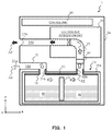
- the electrostatic atomizing apparatus 1 includes a main body portion 1 a, a water container 10 , a first air flow path 210 , a second air flow path 220 , a duct member 30 , an electrostatic atomization unit 70 , a control unit 80 , and a fan 90 .
- the electrostatic atomizing apparatus 1 further includes a container detachment mechanism 50 (described later).
- the water container 10 (example of the container), includes a container main body 10 a that holds water.
- the water container 10 includes a first ventilation hole 11 and a second ventilation hole 12 in a top surface (surface on the Z-axis positive side) of the container main body 10 a.
- the first ventilation hole 11 forms a path for introducing non-humidified air into the container main body 10 a.
- the second ventilation hole 12 forms a path for sending humidified air from the container main body 10 a to the electrostatic atomization unit 70 .
- the first ventilation hole 11 for introducing air and the second ventilation hole 12 for sending air are located at two locations in an upper portion 101 ( FIG. 3 ) of the container main body 10 a.
- the ventilation holes 11 and 12 are open in the same direction.
- the humidification filter 13 (example of the humidifier) humidifies low humidity air that flows through the first ventilation hole.
- the humidification filter 13 is a corrugated humidification filter that absorbs and holds the water held in the container main body 10 a. In this state, low humidity air is passed through the gaps in the humidification filter 13 and, as a result, the water vaporizes from the surfaces in the humidification filter 13 , the air is humidified, and high humidification air is produced.
- the humidification filter 13 has flame retardant characteristics and is less likely to burn in the event of a fire in the aircraft, for example.
- the humidification filter 13 may also have corrosion resistance characteristics. Since the water W evaporates from the surface portions of the humidification filter 13 and at least the required humidity is maintained, continuous electrostatic atomization during long flights is possible.
- a different humidification device is provided in place of the humidification filter 13 .
- a vibration-type humidifier or a heating-type humidifier may be used.
- the first air flow path 210 extends from a first end, namely an air suction port 21 a, to a second end 21 b that connects to the first ventilation hole 11 of the water container 10 .
- the first air flow path 210 suctions air through the air suction port 21 a in accordance with the air flow generated by the fan 90 , and sends the air to the first ventilation hole 11 of the water container 10 .
- This suctioned air is low humidity air A 1 that is insufficient for condensation water production.
- the electrostatic atomization unit 70 (example of the electrostatic atomization unit) is disposed on the second air flow path 220 .
- the electrostatic atomization unit 70 includes, for example, a cooler, a water application electrode, and a counter electrode (all not illustrated in the drawings). High voltage is applied to the water application electrode and the counter electrode, and the cooler cools the water application electrode. As a result, the water in the high humidity air A 2 condensates on the electrode and charged particulate water is produced. Air A 3 that contains the charged particulate water is discharged out of the apparatus through the air exhaust port 22 b.
- the control unit 80 includes, for example, a processor such as a central processing unit (CPU).
- the control unit 80 controls the operations of the electrostatic atomization unit 70 , the fan 90 (described later), and the like in accordance with a program stored in memory.
- the water container 10 - 2 includes a container main body 10 a that holds water W.
- the container main body 10 a includes an upper portion 101 , a bottom portion 102 , and left and right container side portions 103 and 104 that connect the upper portion 101 and the bottom portion 102 .
- the water container 10 - 2 includes a first ventilation hole 11 and a second ventilation hole 12 that penetrate the upper portion 101 of the container main body 10 a.
- the first lid 111 and the second lid 112 are formed from a material with a smaller specific gravity than the water W.
- the first lid 111 and the second lid 112 are formed from a resin material or the like that has a lower density than the water W.
- FIG. 10A illustrates the water container 10 - 2 in a normal state, that is, when installed horizontally.
- the first lid 111 pivots about the fulcrum 111 a in the opening direction due to the weight of the first lid 111 , and the portion of the first lid 111 contacting the surface of the water W floats on the water surface.
- the second lid 112 pivots about the fulcrum 112 a in the opening direction due to the weight of the second lid 112 , and the portion of the second lid 112 contacting the surface of the water W floats on the water surface.
- the term “comprising” and its derivatives, as used herein, are intended to be open ended terms that specify the presence of the stated features, elements, components, groups, integers, and/or steps, but do not exclude the presence of other unstated features, elements, components, groups, integers and/or steps.
- the foregoing also applies to words having similar meanings such as the terms “including,” “having,” and their derivatives.
- the terms “part,” “section,” “portion,” “member,” or “element” when used in the singular can have the dual meaning of a single part or a plurality of parts.
Landscapes
- Engineering & Computer Science (AREA)
- Chemical & Material Sciences (AREA)
- General Engineering & Computer Science (AREA)
- Combustion & Propulsion (AREA)
- Mechanical Engineering (AREA)
- Health & Medical Sciences (AREA)
- General Health & Medical Sciences (AREA)
- Pulmonology (AREA)
- Aviation & Aerospace Engineering (AREA)
- Dispersion Chemistry (AREA)
- Analytical Chemistry (AREA)
- Electrostatic Spraying Apparatus (AREA)
- Air Conditioning Control Device (AREA)
- Air Humidification (AREA)
Abstract
Description
- This application claims benefit to U.S. provisional application No. 62/734,257, filed on Sep. 21, 2018. The entire disclosure of U.S. provisional application 62/734,257 is hereby incorporated herein by reference.
- The present disclosure relates to an electrostatic atomizing apparatus that produces charged particulate water, and an electrostatic atomizing method thereof.
- In the related art, a method is known for producing charged particulate water by applying high voltage to an electrode on which water is held, and using that charged particulate water to inactivate pollen antigens, molds, fungi, viruses, and the like. In this method, the water in the air is electrostatically atomized to produce charged particulate water having a particle size of 3 to 50 nm and the charged particulate water are reacted with any of pollen antigens, molds, fungi, and viruses to inactivate the pollen antigens, molds, fungi, viruses, and the like (for example, Japanese Patent No. 4877410).
- Atmospheres at high altitudes of 10 km are low humidity environments. Cabins of aircraft flying at high altitudes are ventilated by introducing outside air. The cabin humidity is affected by the outside humidity, resulting in low humidity states such as, for example, a relative humidity of 10 degrees. A predetermined humidity is needed for electrostatic atomization.
- The present disclosure provides an electrostatic atomizing apparatus and a method that are effective for electrostatic atomization even in low humidity environments.
- The electrostatic atomizing apparatus according to the present disclosure includes a main body portion, a container, a first air flow path, a second air flow path, an electrostatic atomization unit, and an air flow generation unit. The container is detachable from the main body portion, is capable of storing liquid, and includes a first ventilation hole and a second ventilation hole. The first air flow path includes a first end that includes an air suction port, and a second end that connects to the first ventilation hole. The second air flow path includes a third end that connects to the second ventilation hole, and a fourth end that includes an air exhaust port. The electrostatic atomization unit is disposed on the second air flow path. The air flow generation unit generates an air flow that causes air to flow through the first air flow path, through the container, and through the second air flow path.
- The electrostatic atomizing method according to the present disclosure includes introducing air that was taken in through an air suction port into a container that store a liquid, humidifying the air by causing the air to flow through the container, exhausting the humidified air from the container, producing charged particulate water by causing water in the humidified air to condensate on an electrode and applying voltage to the electrode, and exhausting air containing the charge particulate water through an air discharge port.
-
FIG. 1 illustrates the basic configuration of an electrostatic atomizing apparatus according toEmbodiment 1; -
FIG. 2 is a plan view of a duct member according to Embodiment 1; -
FIG. 3 illustrates a state in which a water container is attached to the electrostatic atomizing apparatus according toEmbodiment 1; -
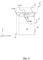
FIG. 4 is a cross-sectional view illustrating the electrostatic atomizing apparatus ofFIG. 3 from another direction; -
FIG. 5 illustrates a state in which the water container is removed from the electrostatic atomizing apparatus according toEmbodiment 1; -
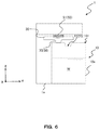
FIG. 6 is a cross-sectional view illustrating the electrostatic atomizing apparatus ofFIG. 5 from another direction; -
FIG. 7 illustrates a water container to be attached to an electrostatic atomizing apparatus according toEmbodiment 2; -
FIG. 8 is a plan view of the water container according toEmbodiment 2; -
FIG. 9A illustrates a lid of the water container ofEmbodiment 2 in an open state; -
FIG. 9B illustrates the lid of the water container ofEmbodiment 2 in a closed state; -
FIG. 10A illustrates the water container according toEmbodiment 2 in a normal state; -
FIG. 10B illustrates the water container according toEmbodiment 2 in a tilted state; -
FIG. 11 illustrates a water container according to a Modification Example ofEmbodiment 2; and -
FIG. 12 illustrates a water container according to another Modification Example ofEmbodiment 2. - Next, embodiments of the present disclosure will be described in detail while referencing the drawings. Note that, in some cases, unnecessarily detailed descriptions are foregone. For example, detailed descriptions of well-known matters and redundant descriptions of configurations and constituents that are substantially the same may be foregone.
- Note that the following description and attached drawings are provided for the purpose of enabling a person skilled in the art to comprehend the present disclosure, and are not intended to limit the matters recited in the claims.
- In the following description, for convenience, the Z-axis direction is referred to as the “up-down direction”, the Z-axis positive side is referred to as “up”, and the Z-axis negative side is referred to as “down.” However, the attachment mode of the electrostatic atomizing
apparatus 1 is not limited thereto and various attachment modes are possible. Unless otherwise stated, the Z-axis negative direction may not indicate the direction of gravity. - In the following embodiments, the term “electrostatic atomization” means cooling a water application electrode and causing the water in the air to condensate on the water application electrode to produce charged particulate water. There are two types of water application electrodes, namely a direct type and an electrode cooling type that does not require water to be supplied. In the following description of the embodiments, an electrode cooling type electrostatic atomizing method is used.
- As illustrated in
FIG. 1 , the electrostatic atomizingapparatus 1 includes amain body portion 1 a, awater container 10, a firstair flow path 210, a secondair flow path 220, aduct member 30, anelectrostatic atomization unit 70, acontrol unit 80, and a fan 90. The electrostatic atomizingapparatus 1 further includes a container detachment mechanism 50 (described later). - The
main body portion 1 a is a housing and accommodates thewater container 10, the firstair flow path 210, the secondair flow path 220, theelectrostatic atomization unit 70, thecontrol unit 80, and the fan 90. - The water container 10 (example of the container), includes a container
main body 10 a that holds water. Thewater container 10 includes afirst ventilation hole 11 and asecond ventilation hole 12 in a top surface (surface on the Z-axis positive side) of the containermain body 10 a. Thefirst ventilation hole 11 forms a path for introducing non-humidified air into the containermain body 10 a. Thesecond ventilation hole 12 forms a path for sending humidified air from the containermain body 10 a to theelectrostatic atomization unit 70. Thefirst ventilation hole 11 for introducing air and thesecond ventilation hole 12 for sending air are located at two locations in an upper portion 101 (FIG. 3 ) of the containermain body 10 a. Theventilation holes ventilation holes upper portion 101 of the containermain body 10 a so that the water W in the containermain body 10 a does not spill. Additionally, theventilation holes main body 10 a does not spill. In one example, the size of theventilation holes - Moreover, the
upper portion 101 of the containermain body 10 a may be implemented as a sealable lid. A user can remove thewater container 10 from theelectrostatic atomizing apparatus 1 and open theupper portion 101 of the containermain body 10 a when replenishing the water W in the containermain body 10 a. - The
first ventilation hole 11 and thesecond ventilation hole 12 are open in the same direction and are provided in the top side of the containermain body 10 a. As a result of this configuration, the risk of water splashing in the aircraft, which constantly vibrates and has difficulty maintaining a horizontal posture, is reduced. - The
water container 10 further includes ahumidification filter 13 in the containermain body 10 a. Thehumidification filter 13 is erected (in the middle in the X-axis direction) between thefirst ventilation hole 11 and thesecond ventilation hole 12. Due to this arrangement, thehumidification filter 13 is able to efficiently supply water to the low humidity air that is introduced from outside, and high humidity air can be produced. - The humidification filter 13 (example of the humidifier) humidifies low humidity air that flows through the first ventilation hole. In one example, the
humidification filter 13 is a corrugated humidification filter that absorbs and holds the water held in the containermain body 10 a. In this state, low humidity air is passed through the gaps in thehumidification filter 13 and, as a result, the water vaporizes from the surfaces in thehumidification filter 13, the air is humidified, and high humidification air is produced. Note that thehumidification filter 13 has flame retardant characteristics and is less likely to burn in the event of a fire in the aircraft, for example. Thehumidification filter 13 may also have corrosion resistance characteristics. Since the water W evaporates from the surface portions of thehumidification filter 13 and at least the required humidity is maintained, continuous electrostatic atomization during long flights is possible. - Note that configurations are possible in which a different humidification device is provided in place of the
humidification filter 13. For example, a vibration-type humidifier or a heating-type humidifier may be used. - The first
air flow path 210 extends from a first end, namely anair suction port 21 a, to asecond end 21 b that connects to thefirst ventilation hole 11 of thewater container 10. The firstair flow path 210 suctions air through theair suction port 21 a in accordance with the air flow generated by the fan 90, and sends the air to thefirst ventilation hole 11 of thewater container 10. This suctioned air is low humidity air A1 that is insufficient for condensation water production. - The second
air flow path 220 extends from athird end 22 a that connects to thesecond ventilation hole 12 of thewater container 10 to a fourth end, namely anair exhaust port 22 b. The secondair flow path 220 sends the air A2 that was humidified in thewater container 10 from thesecond ventilation hole 12 to theelectrostatic atomization unit 70 in accordance with the air flow generated by the fan 90. Furthermore, the secondair flow path 220 sends the air A3 that contains charged particulate water produced by theelectrostatic atomization unit 70 to theair exhaust port 22 b, and discharges the air A3 out of the apparatus. - As illustrated in
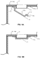
FIG. 2 , the duct member 30 (example of the duct member) is an integrally molded part, and includes afirst duct 31 and asecond duct 32. Thefirst duct 31 connects to themain body portion 1 a and thefirst ventilation hole 11 of thewater container 10. Thefirst duct 31 forms a portion of the firstair flow path 210. Thesecond duct 32 connects to themain body portion 1 a and thesecond ventilation hole 12 ofwater container 10. Thesecond duct 32 forms a portion of the secondair flow path 220. As illustrated inFIGS. 3 and 5 , thefirst duct 31 and thesecond duct 32 respectively include open ends 31 a and 32 a. The open ends 31 a and 32 a each have a hook-shaped cross-section. The open ends 31 a and 32 a respectively include abuttingsurfaces 31 b and 32 b that face the side of thewater container 10 that is attached to themain body portion 1 a. The abutting surfaces 31 b and 32 b abut against step portions formed in corresponding portions of themain body portion 1 a. Specifically, a configuration is provided in which the surfaces of theduct member 30 and themain body portion 1 a abut against each other in a direction crossing or in a direction substantially orthogonal to the air flow direction. Due to this configuration, a structure can be formed in which the water W in thewater container 10 is less likely to leak from the boundary portion between theduct member 30 and themain body portion 1 a. - The electrostatic atomization unit 70 (example of the electrostatic atomization unit) is disposed on the second
air flow path 220. As is commonly known, theelectrostatic atomization unit 70 includes, for example, a cooler, a water application electrode, and a counter electrode (all not illustrated in the drawings). High voltage is applied to the water application electrode and the counter electrode, and the cooler cools the water application electrode. As a result, the water in the high humidity air A2 condensates on the electrode and charged particulate water is produced. Air A3 that contains the charged particulate water is discharged out of the apparatus through theair exhaust port 22 b. - The
control unit 80 includes, for example, a processor such as a central processing unit (CPU). Thecontrol unit 80 controls the operations of theelectrostatic atomization unit 70, the fan 90 (described later), and the like in accordance with a program stored in memory. - The fan 90 (example of the air flow generation unit) generates an air flow that causes air to flow through the first
air flow path 210, through thecontainer 10, and through the secondair flow path 220. Due to the operation of the fan 90, the air is sent sequentially from theair suction port 21 a to the firstair flow path 210, thewater container 10, theelectrostatic atomization unit 70, and theexhaust port 22 b. Note that the fan 90 is not limited to being disposed at the position illustrated inFIG. 1 . For example, the fan 90 may be disposed at a position near theair suction port 31 a, or may be disposed at a position before theair exhaust port 22 b. Moreover, the air flow generation device is not limited to the fan 90, and other devices and methods that generate an air flow may be used. - Various equipment is installed in the aircraft, and space is limited. Among this equipment, there may be electronic devices that could fail due to drops of water that adhere as a result of water intrusion or submersion. The
electrostatic atomizing apparatus 1 of the present disclosure is a device that handles water, and the water is replenished regularly. As such, thewater container 10 has a structure that enables thewater container 10 to be detached from themain body portion 1 a of theelectrostatic atomizing apparatus 1. When thewater container 10 is to be removed from or attached to themain body portion 1 a, thewater container 10 is cut off from theduct member 30. Consequently, there is a possibility of the water W in thewater container 10 leaking out. - The
electrostatic atomizing apparatus 1 according to the present disclosure includes thecontainer detachment mechanism 50 illustrated inFIGS. 3 to 6 and described below and, as such, water leakage is less likely to occur when attaching and detaching thewater container 10. - The container detachment mechanism 50 (example of the container detachment mechanism) moves the
duct member 30 up and down with respect to thewater container 10 and, when thewater container 10 is attached to themain body portion 1 a, creates a state in which theduct member 30 is in pressure contact with thewater container 10. Specifically, as illustrated inFIGS. 3 to 6 , thecontainer detachment mechanism 50 includes a spring 51 (example of the first elastic member) disposed between themain body portion 1 a and theduct member 30, a protrusion 35 (example of the first engaging portion) formed on the lower portion of theduct member 30, and a recess 15 (example of the second engaging portion) formed in theupper portion 101 of the containermain body 10 a. -
FIGS. 3 and 4 illustrate a state in which thewater container 10 is mounted on themain body portion 1 a, that is, a state in which theelectrostatic atomizing apparatus 1 is operable.FIG. 4 illustrates a YZ cross-section of thewater container 10 depicted inFIG. 3 . Thespring 51 has urging force that acts toward thewater container 10 side, that is, that acts in the Z-axis negative direction. As illustrated inFIG. 4 , theprotrusion 35 protrudes from the lower (Z-axis negative side) surface of theduct member 30. Therecess 15 is formed in theupper portion 101 of the containermain body 10 a and is concave in the Z-axis negative direction. As illustrated inFIG. 2 , theprotrusion 35 and therecess 15 are formed long in the X-axis direction along the longitudinal direction of the containermain body 10 a. While thewater container 10 is mounted on themain body portion 1 a, theprotrusion 35 is housed in and engaged with therecess 15. At this time, thespring 51 is in a state compressed in the Z-axis positive direction, against the urging force. Due to the urging force of thespring 51, theduct member 30 and thewater container 10 are brought into close contact with each other, and theprotrusion 35 engages with therecess 15. As a result, displacement of thewater container 10 is less likely to occur, even in the case of a degree of vibration. Thus, water leakage such as that caused by thewater container 10 being removed from theduct member 30 can be prevented. - Note that a configuration is possible in which a recess is provided in the
duct member 30 and a protrusion is provided on thewater container 10 side. - A cushion material 39 (example of the second elastic member) is disposed between the
duct member 30 and thewater container 10. Thecushion material 39 is disposed between thefirst duct 31 and the surroundings of thefirst ventilation hole 11, and between thesecond duct 32 and the surroundings of thesecond ventilation hole 12. Thecushion material 39 improves the adhesion of thewater container 10 to theduct member 30 and, as a result water leakage can be effectively prevented. - In an electrostatic atomizing method using the
electrostatic atomizing apparatus 1 according toEmbodiment 1, as illustrated inFIG. 1 , the air A1 suctioned through theair suction port 21 a by the air flow generated by the fan 90 flows through the firstair flow path 210 and is introduced into thewater container 10 in which the water W is stored. The air A1 is humidified as a result of passing through thewater container 10. The humidified air A2 is exhausted from thewater container 10. In theelectrostatic atomization unit 70, charged particulate water is produced by causing water in the humidified air A2 to condensate on an electrode and applying voltage to the electrode. The air A3 that contains the charged particulate water is exhausted through theair exhaust port 22 b. -
FIGS. 5 and 6 illustrate a state when thewater container 10 is removed from themain body portion 1 a, that is, a state in which theelectrostatic atomizing apparatus 1 is not operating. InFIG. 6 , when thewater container 10 is pulled in the Y-axis positive direction, theprotrusion 35 of theduct member 30 separates from therecess 15 in the top surface of the containermain body 10 a, and becomes seated on a flat portion of the top surface that is not recessed. As a result, theduct member 30 is pressed in the Z-axis positive direction and presses thespring 51 up. As a result, thespring 51 compressed further against the urging force. When thewater container 10 is further pulled in the Y-axis positive direction, thewater container 10 separates from theduct member 30 and can be removed from themain body portion 1 a. When thewater container 10 is removed, theduct member 30 moves in the Z-axis negative direction due to the urging force of thespring 51 or the weight of theduct member 30 itself. After the water W in the removedwater container 10 has been replenished, thewater container 10 is attached to themain body portion 1 a. As illustrated inFIG. 6 , at this time, when thewater container 10 is pressed in the Y-axis negative direction, theduct member 30 is pressed up and becomes seated on the top surface of the containermain body 10 a against the urging force of thespring 51. When thewater container 10 is pressed further in the Y-axis negative direction, theprotrusion 35 mates with therecess 15. Thus, thewater container 10 is attached to themain body portion 1 a as illustrated inFIGS. 3 and 4 . - In low humidity environments such as in the cabins of aircraft flying at high altitudes, the humidity required to produce condensation water cannot be reached and, thus, it is not possible to obtain condensation water. Alternatively, the condensation water freezes due to intense cooling on the endothermic surface and, thus, it is not possible to obtain condensation water. This leads to the problem of not being able to perform electrostatic atomization.
- The
electrostatic atomizing apparatus 1 or the electrostatic atomizing method according toEmbodiment 1 causes the low humidity air A1 suctioned through theair suction port 21 a to pass through thewater container 10, thereby humidifying the air A1, causes the humidified air A2 to pass through theelectrostatic atomization unit 70, and exhausts the air A3 containing the charged particulate water. As such, even if the outside air that is taken in is low humidity air, humidified air can be constantly delivered to theelectrostatic atomization unit 70. This, the condensation water necessary for electrostatic atomization can be produced, and electrostatic atomization can be performed even in low humidity environments. - The
electrostatic atomizing apparatus 1 according toEmbodiment 1 includes theduct member 30 and thecontainer detachment mechanism 50. Theduct member 30 includes thefirst duct 31 that connects to thefirst ventilation hole 11 and that forms a portion of the firstair flow path 210, and thesecond duct 32 that connects to thesecond ventilation hole 12 and that forms a portion of the secondair flow path 220. Thecontainer detachment mechanism 50 presses theduct member 30 against thewater container 10 that is attached to themain body portion 1 a. As a result of this configuration, water leakage from thewater container 10 can be prevented in cases in which, during the operation of theelectrostatic atomizing apparatus 1, vibration occurs or the aircraft cannot maintain a horizontal posture such as during take-off and landing. Moreover, since theduct member 30 can be moved up and down, thewater container 10 is easier to attach and detach. - With the
electrostatic atomizing apparatus 1 or the electrostatic atomizing method according toEmbodiment 1, for a 24 hour flight, it is possible to perform electrostatic atomization with 100 ml or less of water. This is because only the insufficient portion of the necessary water is replenished, based on the humidity contained in the air. Thus, the amount of water can be reduced compared to the direct water supply electrostatic atomization as disclosed in Japanese Patent No. 4877410. - In the
electrostatic atomizing apparatus 1 according toEmbodiment 1, the various electronic devices such as theelectrostatic atomization unit 70, thecontrol unit 80, and the fan 90 can be disposed upward from thewater container 10. As a result of this configuration, even if water leakage occurs, water is less likely to enter into theelectrostatic atomizing apparatus 1, and therefore, it is possible to reduce the risk of electric leaks, short circuits, and the like. - In
Embodiment 2, a water container 10-2 that is detachable from theelectrostatic atomizing apparatus 1 differs from thewater container 10 ofEmbodiment 1 in that the water container 10-2 includeslids Embodiment 1 are primarily described while referencingFIGS. 7 to 10 . Note that constituents that have the same structures and functions as inEmbodiment 1 are marked with the same reference numerals. The arrow G illustrated in the drawings indicates the direction of gravity. - As illustrated in
FIG. 7 , the water container 10-2 includes a containermain body 10 a that holds water W. As inEmbodiment 1, the containermain body 10 a includes anupper portion 101, abottom portion 102, and left and rightcontainer side portions upper portion 101 and thebottom portion 102. The water container 10-2 includes afirst ventilation hole 11 and asecond ventilation hole 12 that penetrate theupper portion 101 of the containermain body 10 a. - As illustrated in
FIG. 7 , the water container 10-2 includes afirst lid 111 and asecond lid 112. As illustrated inFIG. 8 , when viewed planarly, thefirst lid 111 and thesecond lid 112 have round shapes. As a result of this configuration, thefirst lid 111 and thesecond lid 112 can close thefirst ventilation hole 11 and thesecond ventilation hole 12, respectively. It is sufficient that the planar shapes of thefirst lid 111 and thesecond lid 112 match the shapes of the ventilation holes 11 and 12. Thefirst lid 111 closes thefirst ventilation hole 11 due to a change in the surface of the water W when water is stored in the containermain body 10 a. Thesecond lid 112 closes thesecond ventilation hole 12 due to a change in the surface of the water W when water is stored in the containermain body 10 a. - As illustrated in
FIGS. 10A and 10B , thefirst lid 111 includes afulcrum 111 a that is closer to thecontainer side portion 103 than thefirst ventilation hole 11, and thefirst lid 111 is pivotable around thefulcrum 111 a with respect to thefirst ventilation hole 11. Likewise, thesecond lid 112 has afulcrum 112 a that is closer to thecontainer side portion 104 than thesecond ventilation hole 12, and thesecond lid 112 is pivotable around thefulcrum 112 a with respect to thesecond ventilation hole 12. Thefirst lid 111 and thesecond lid 112 respectively include fulcrums that are closer to thecontainer side portions main body 10 a. - The
first lid 111 and thesecond lid 112 are formed from a material with a smaller specific gravity than the water W. For example, thefirst lid 111 and thesecond lid 112 are formed from a resin material or the like that has a lower density than the water W. - As illustrated in
FIGS. 9A and 9B , a rim surrounding thefirst ventilation hole 11 of the containermain body 10 a includes a protrudingedge portion 11 c that protrudes more toward the surface of the water W than aninside surface 101 a of theupper portion 101 of the containermain body 10 a. Thefirst lid 111 includes arecess 111 c that accommodates the protrudingedge portion 11 c when thefirst ventilation hole 11 is closed, and anextended portion 111 e that extends outward from therecess 111 c. Theextended portion 111 e includes anabutting surface 111 f that is capable of abutting against aninside surface 101 a of theupper portion 101 of the containermain body 10 a when thefirst lid 111 closes thefirst ventilation hole 11. As illustrated inFIG. 9B , since theabutting surface 111 f abuts against theupper portion 101 of the containermain body 10 a, thefirst lid 111 can effectively close thefirst ventilation hole 11. Thesecond lid 112 has the same configuration as thefirst lid 111, and a protruding edge portion that is the same as the protrudingedge portion 11 c is formed on the rim surrounding thesecond ventilation hole 12 of the containermain body 10 a. As such, description thereof is foregone. -
FIG. 10A illustrates the water container 10-2 in a normal state, that is, when installed horizontally. At this time, thefirst lid 111 pivots about thefulcrum 111 a in the opening direction due to the weight of thefirst lid 111, and the portion of thefirst lid 111 contacting the surface of the water W floats on the water surface. Likewise, thesecond lid 112 pivots about thefulcrum 112 a in the opening direction due to the weight of thesecond lid 112, and the portion of thesecond lid 112 contacting the surface of the water W floats on the water surface. -
FIG. 10B illustrates the water container 10-2 in a state tilted to theside portion 103 side. At this time, the water W is also tilted to theside portion 103 side and, as such, the surface of the water W rises on theside portion 103 side. As a result, due to the buoyant force of the water W, thefirst lid 111 is pressed, and thefirst lid 111 pivots in the direction of closing thefirst ventilation hole 11. In cases in which thewater container 10 is tilted further, thefirst ventilation hole 11 is closed before the water surface reaches thefirst ventilation hole 11, as illustrated inFIG. 9B . Meanwhile, sincesecond lid 112 is no longer subjected to the buoyant force of the water W due to the water surface lowering, thesecond lid 112 is in an open state. - In cases in which the water container 10-2 tilts to the
side portion 104 side, opposite to the behavior described above, thesecond lid 112 pivots in the closing direction, and thefirst lid 111 pivots in the opening direction. - In aircraft and the like, vibration constantly occurs during movement and horizontal posture may by impossible to maintain at take-off and landing. As such, the water container 10-2 attached to the
electrostatic atomizing apparatus 1 tilts, the water W waves or splashes, and the like. As a result, the surface of the stored water W changes, and there is a possibility of the water W leaking out through the ventilation holes 11 and 12 of the water container 10-2. This leakage may lead to electric leaks, short circuits, and the like in theelectrostatic atomizing apparatus 1. - However, as described in Embodiment, the ventilation holes 11 and 12 of the water container 10-2 are air flow paths and, as such, must remain open during the operation of the
electrostatic atomizing apparatus 1. - The water container 10-2 according to
Embodiment 2 includes thelids lids fulcrums container side portions lids fulcrums - Thus, a configuration is provided in which the surface of the water W does not rise higher than the
lids lids electrostatic atomizing apparatus 1. Meanwhile, since thelids - Additionally, the
electrostatic atomizing apparatus 1 according toEmbodiment 2 has a structure that reduces the possibility of water leakage. As such, in aircraft environments where there is a plurality of electrical equipment in neighboring areas, it is possible to reduce the risk of the occurrence of electric leaks, short circuits, and the like and improve safety. - As illustrated in
FIG. 11 , a configuration is possible in which the water container 10-2 includesguides 18 that guide, in accordance with the pivoting of thefirst lid 111 and thesecond lid 112, the ends on the sides of thefirst lid 111 and thesecond lid 112 opposite thefulcrums first lid 111 and thesecond lid 112 can be more easily controlled, and smooth opening and closing operations can be performed. - As illustrated in
FIG. 12 , a configuration is possible in which thefirst lid 111 and thesecond lid 112 include an expandedportion 19 on the ends of the sides of thefirst lid 111 and thesecond lid 112 opposite thefulcrums first lid 111 and thesecond lid 112 will be more easily subjected to the buoyant force of the water W and, as such, the water W can be effectively prevented from flowing above thelids - The embodiments described above have been given as examples of the technology that is disclosed in the present application. However, the technology according to the present disclosure is not limited thereto, and changes, substitutions, additions, and omissions can be applied to the embodiments. Moreover, the constituents described in the embodiments may be combined to create new embodiments.
- (1) In the embodiments described above, the shapes of the
water container 10 or 10-2, the ventilation holes 11 and 12, and the other constituents are not limited to the shapes illustrated in the drawings. For example, a configuration is possible in which the containermain body 10 a has a shape other that a rectangular solid or a cube. For example, the containermain body 10 a may have a rounded shape. The shapes of the ventilation holes 11 and 12 are not limited to circular, and may be square, rectangular, or the like. - In the embodiments described above, the number of the ventilation holes 11 and 12 of the
water container 10 or 10-2 is not limited. The numbers of the ventilation holes 11 and 12 may be one or may be three or more. - (2) In the embodiments described above, the liquid stored in the
water container 10 or 10-2 is not limited to the water W. Any other liquid that can be evaporated may be used. - (3) In the embodiments described above, a water absorbing member may be provided in the
water container 10 or 10-2. The water absorbing member is, for example, a mass of absorbent cotton, a water absorbing polymer, or the like, and is disposed in the containermain body 10 a. The water absorbing member prevents the water from moving freely as a liquid. As a result of this configuration, the water is prevented from splashing in and leaking out of theelectrostatic atomizing apparatus 1, even at take-off and landing of the aircraft or when the aircraft vibrates. However, if the water absorbing member absorbs too much of the water and the water cannot be supplied to thehumidification filter 13, humidification will not be possible. Therefore, it is preferable that the size and water holding characteristics of the water absorbing member be set so that a degree of water can be supplied instead of the water being completely absorbed and retained. - (4) In the embodiments described above, the
duct member 30 is implemented as an integrally molded part, but is not limited thereto. For example, a configuration is possible in which thefirst duct 31 and thesecond duct 32 are attached to themain body portion 1 a as separate components. Additionally, a configuration is possible in which theduct member 30 is not disposed and, for example, a structure is provided in which pipe portions, formed by extending rim portions of the ventilation holes 11 and 12 of thewater container 10 or 10-2, are directly attached to the air flow paths of themain body portion 1 a. Alternatively, a structure may be provided in which pipes, formed by extending rim portions of thesecond end 21 b and thethird end 22 a of the air flow paths of themain body portion 1 a, are directly attached to the ventilation holes 11 and 12 of thewater container 10 or 10-2. - (5) The structure for preventing water leakage while the
water container 10 or 10-2 is removed from theelectrostatic atomizing apparatus 1 is not limited to that described in the embodiments described above. For example, a configuration is possible in which a cap, a check valve, or a selective membrane that is gas-permeable (including water vapor), but not liquid-permeable, is provided at the connecting portion between themain body portion 1 a (or the duct member 30) and thewater container 10 or 10-2. - (6) The water W stored in the
water container 10 or 10-2 may corrode when exposed to air for an extended period of time. Theduct member 30 may have a removable structure that accompanies the removal of thewater container 10 or 10-2 and/or thehumidification filter 13. As a result of this configuration, not only thewater container 10 or 10-2, but also theduct member 30 to which corroded water has adhered can be replaced, and an odor-free and corrosion-free state can be maintained. Additionally, the removedwater container 10 or 10-2 and theduct member 30 may be cleaned and reused/reinstalled. In this case, the removedwater container 10 or 10-2 and theduct member 30 can be used repeatedly, and costs associated with facilities and equipment can be reduced. - Additionally, a configuration is possible in which the container
main body 10 a of thewater container 10 or 10-2, thehumidification filter 13, and theduct member 30 are individually removed and replaced or disposed of at different times. - (7) In the embodiments described above, an example is described that focuses on an aircraft as the space in which the
electrostatic atomizing apparatus 1 is used, but the space in which theelectrostatic atomizing apparatus 1 is used is not limited thereto. For example, theelectrostatic atomizing apparatus 1 may be installed in a train, a bus, a marine vessel, or other vehicle. Theelectrostatic atomizing apparatus 1 or the water container 10-2 according to the embodiments described above can demonstrate the advantageous benefits described above even when used in other vehicles in which vibration occurs such as trains, marine vessels, and the like, or in spaces with low humidity environments. - (8) The
water container 10 that includes thecontainer detachment mechanism 50 and the water container 10-2 that includes thelids electrostatic atomizing apparatus 1. Thewater container 10 and the water container 10-2 are usable in devices such as humidifiers or air cleaners that include a container that stores a liquid such as the water W, for example. - In understanding the scope of the present disclosure, the term “configured” as used herein to describe a component, section, or a part of a device includes hardware and/or software that is constructed and/or programmed to carry out the desired function.
- In understanding the scope of the present disclosure, the term “comprising” and its derivatives, as used herein, are intended to be open ended terms that specify the presence of the stated features, elements, components, groups, integers, and/or steps, but do not exclude the presence of other unstated features, elements, components, groups, integers and/or steps. The foregoing also applies to words having similar meanings such as the terms “including,” “having,” and their derivatives. Also, the terms “part,” “section,” “portion,” “member,” or “element” when used in the singular can have the dual meaning of a single part or a plurality of parts. Also as used herein to describe the above embodiment(s), the following directional terms “forward”, “rearward”, “above”, “downward”, “vertical”, “horizontal”, “below” and “transverse” as well as any other similar directional terms refer to those directions of a device.
- Terms that are expressed as “means-plus function” in the claims should include any structure that can be utilized to carry out the function of that part of the present disclosure. Finally, terms of degree such as “substantially,” “about,” and “approximately” as used herein mean a reasonable amount of deviation of the modified term such that the end result is not significantly changed. For example, these terms can be construed as including a deviation of at least ±5% of the modified term if this deviation would not negate the meaning of the word it modifies.
- While only selected exemplary embodiments have been chosen to illustrate the present invention, it will be apparent to those skilled in the art from this disclosure that various changes and modifications can be made herein without departing from the scope of the invention as defined in the appended claims. For example, the size, shape, location or orientation of the various components can be changed as needed and/or desired. Components that are shown directly connected or contacting each other can have intermediate structures disposed between them. The functions of one element can be performed by two, and vice versa. The structures and functions of one embodiment can be adopted in another embodiment. It is not necessary for all advantages to be present in a particular embodiment at the same time. Every feature which is unique from the prior art, alone or in combination with other features, also should be considered a separate description of further inventions by the applicant, including the structural and/or functional concepts embodied by such feature(s). Thus, the foregoing descriptions of the exemplary embodiments according to the present invention are provided for illustration only, and not for the purpose of limiting the invention as defined by the appended claims and their equivalents.
Claims (12)
Priority Applications (1)
| Application Number | Priority Date | Filing Date | Title |
|---|---|---|---|
| US16/296,847 US11285499B2 (en) | 2018-09-21 | 2019-03-08 | Electrostatic atomizing apparatus and electrostatic atomizing method |
Applications Claiming Priority (2)
| Application Number | Priority Date | Filing Date | Title |
|---|---|---|---|
| US201862734257P | 2018-09-21 | 2018-09-21 | |
| US16/296,847 US11285499B2 (en) | 2018-09-21 | 2019-03-08 | Electrostatic atomizing apparatus and electrostatic atomizing method |
Publications (2)
| Publication Number | Publication Date |
|---|---|
| US20200094271A1 true US20200094271A1 (en) | 2020-03-26 |
| US11285499B2 US11285499B2 (en) | 2022-03-29 |
Family
ID=66217669
Family Applications (3)
| Application Number | Title | Priority Date | Filing Date |
|---|---|---|---|
| US16/296,847 Active 2040-01-24 US11285499B2 (en) | 2018-09-21 | 2019-03-08 | Electrostatic atomizing apparatus and electrostatic atomizing method |
| US16/296,866 Active 2040-11-04 US11285500B2 (en) | 2018-09-21 | 2019-03-08 | Liquid container, and electrostatic atomizing apparatus with liquid container |
| US16/366,518 Active 2042-12-25 US11998941B2 (en) | 2018-09-21 | 2019-03-27 | Electrostatic atomizing system, and method for fault detection in electrostatic atomizing system |
Family Applications After (2)
| Application Number | Title | Priority Date | Filing Date |
|---|---|---|---|
| US16/296,866 Active 2040-11-04 US11285500B2 (en) | 2018-09-21 | 2019-03-08 | Liquid container, and electrostatic atomizing apparatus with liquid container |
| US16/366,518 Active 2042-12-25 US11998941B2 (en) | 2018-09-21 | 2019-03-27 | Electrostatic atomizing system, and method for fault detection in electrostatic atomizing system |
Country Status (2)
| Country | Link |
|---|---|
| US (3) | US11285499B2 (en) |
| EP (3) | EP3626621B1 (en) |
Families Citing this family (3)
| Publication number | Priority date | Publication date | Assignee | Title |
|---|---|---|---|---|
| EP3898001A1 (en) * | 2018-12-21 | 2021-10-27 | J. Wagner GmbH | Function control for an electrohydrodynamic atomizer |
| CN209819781U (en) * | 2019-01-14 | 2019-12-20 | 深圳市晨北科技有限公司 | Humidifier |
| KR102771153B1 (en) * | 2022-02-25 | 2025-02-24 | 주식회사 씨엠피 | A method of monitoring humidifier for fuel cell and a device thereof |
Family Cites Families (32)
| Publication number | Priority date | Publication date | Assignee | Title |
|---|---|---|---|---|
| US1918128A (en) * | 1931-06-23 | 1933-07-11 | Fred D Pfening Company | Float controlled valve mechanism |
| JPS5113460Y2 (en) | 1971-12-28 | 1976-04-10 | ||
| JPS6416991A (en) | 1987-07-13 | 1989-01-20 | Hitachi Ltd | Nuclear reactor container |
| JP3036963B2 (en) | 1992-04-27 | 2000-04-24 | 三洋電機株式会社 | humidifier |
| US5563811A (en) * | 1993-04-29 | 1996-10-08 | Humonics International Inc. | Microprocessor controlled drive circuit for a liquid nebulizer having a plurality of oscillators |
| US5492676A (en) * | 1993-05-28 | 1996-02-20 | Matsushita Electric Industrial Co., Ltd. | Denitrification system |
| JPH10151314A (en) * | 1996-09-27 | 1998-06-09 | Aiwa Co Ltd | Attaching/detaching mechanism for apparatus for storing liquid such as water |
| US5850976A (en) * | 1997-10-23 | 1998-12-22 | The Eastwood Company | Powder coating application gun and method for using the same |
| JP4154833B2 (en) | 1999-05-20 | 2008-09-24 | セイコーエプソン株式会社 | Liquid consumption state detection method, liquid container, and ink cartridge |
| JP5054809B2 (en) | 2003-08-05 | 2012-10-24 | パナソニック株式会社 | Method for generating charged fine particle water and electrostatic atomizer |
| DE102004014646B3 (en) * | 2004-03-25 | 2005-07-14 | Brita Gmbh | Lid for jug has closing element in form of seesaw turning on axis on lid, having closing plate on one arm and counterweight on other |
| JP4329709B2 (en) | 2005-03-04 | 2009-09-09 | パナソニック電工株式会社 | Electrostatic atomizer |
| JP2006305321A (en) | 2005-03-28 | 2006-11-09 | Matsushita Electric Ind Co Ltd | Air purifier and air purifier and humidifier using the same |
| JP4778276B2 (en) | 2005-07-15 | 2011-09-21 | パナソニック電工株式会社 | Air conditioner |
| JP4595896B2 (en) * | 2006-07-14 | 2010-12-08 | パナソニック電工株式会社 | Electrostatic atomizer |
| JP2009008291A (en) | 2007-06-26 | 2009-01-15 | Toshiba Home Technology Corp | Humidifier |
| JP2009100850A (en) | 2007-10-22 | 2009-05-14 | Kiyohiro Wake | Deodorizing and disinfecting spray device |
| RU2482398C2 (en) | 2007-12-21 | 2013-05-20 | Панасоник Корпорэйшн | Air conditioner |
| DE102008036425B4 (en) | 2008-08-05 | 2010-09-23 | Airbus Deutschland Gmbh | System for targeted local humidification |
| US20130079733A1 (en) | 2009-11-18 | 2013-03-28 | Reckitt Benckiser Llc | Surface Treatment Device and Method |
| JP2012011093A (en) | 2010-07-02 | 2012-01-19 | Toshiba Corp | Vacuum cleaner |
| JP5238047B2 (en) | 2011-02-14 | 2013-07-17 | パナソニック株式会社 | Electrostatic atomizer |
| JP5716166B2 (en) | 2011-11-07 | 2015-05-13 | パナソニックIpマネジメント株式会社 | Humidifier and humidifying hot air fan equipped with the same |
| JP2013108722A (en) * | 2011-11-24 | 2013-06-06 | Panasonic Corp | Air purification device |
| KR101856649B1 (en) * | 2012-03-13 | 2018-05-15 | 삼성전자주식회사 | Humidifier |
| JP5981194B2 (en) * | 2012-03-30 | 2016-08-31 | 住友化学株式会社 | Atomizer |
| JP6011843B2 (en) * | 2012-05-18 | 2016-10-19 | パナソニックIpマネジメント株式会社 | Mist generator and beauty device |
| JP2015072112A (en) | 2013-09-05 | 2015-04-16 | パナソニック株式会社 | Heating and humidifying device |
| JP2016095115A (en) | 2014-11-17 | 2016-05-26 | シャープ株式会社 | Humidifier |
| JP5918429B1 (en) * | 2015-09-28 | 2016-05-18 | 株式会社イースタン | Humidification method and humidifier |
| KR101788201B1 (en) * | 2016-04-08 | 2017-10-20 | 현대자동차주식회사 | Fuel cell system and control method for the same |
| CN105857896B (en) * | 2016-06-06 | 2017-12-29 | 洛阳海惠新材料股份有限公司 | Material taking bottle of packaging container for ethylene glycol antimony |
-
2019
- 2019-02-26 EP EP19159241.9A patent/EP3626621B1/en active Active
- 2019-02-26 EP EP19159242.7A patent/EP3626622B1/en active Active
- 2019-03-08 US US16/296,847 patent/US11285499B2/en active Active
- 2019-03-08 US US16/296,866 patent/US11285500B2/en active Active
- 2019-03-27 EP EP19165433.4A patent/EP3626623B1/en active Active
- 2019-03-27 US US16/366,518 patent/US11998941B2/en active Active
Also Published As
| Publication number | Publication date |
|---|---|
| US11285500B2 (en) | 2022-03-29 |
| US20200094270A1 (en) | 2020-03-26 |
| US20200094279A1 (en) | 2020-03-26 |
| EP3626621B1 (en) | 2021-07-07 |
| US11998941B2 (en) | 2024-06-04 |
| EP3626623A1 (en) | 2020-03-25 |
| EP3626622B1 (en) | 2021-08-18 |
| EP3626622A1 (en) | 2020-03-25 |
| EP3626623B1 (en) | 2021-07-28 |
| EP3626621A1 (en) | 2020-03-25 |
| US11285499B2 (en) | 2022-03-29 |
Similar Documents
| Publication | Publication Date | Title |
|---|---|---|
| US11285499B2 (en) | Electrostatic atomizing apparatus and electrostatic atomizing method | |
| US11123686B2 (en) | Ionic liquid CO2 scrubber for spacecraft | |
| US6511050B2 (en) | Humidifier | |
| JP2010284626A (en) | Electrostatic atomizer and air conditioner | |
| US20100071687A1 (en) | Nebulization Apparatus | |
| CN112654434B (en) | Air conditioner for coating room | |
| KR20200003405A (en) | drone | |
| US12044435B2 (en) | Liquid-retainable device for humidifier | |
| JP5686504B2 (en) | Electrostatic atomizer and air conditioner | |
| US20230085184A1 (en) | Electronics apparatus for a motor vehicle, and motor vehicle | |
| KR20120113026A (en) | Humidifier | |
| US11850617B2 (en) | Electrostatic atomizing apparatus and electrostatic atomizing method | |
| JP2008238061A (en) | Electrostatic atomizer | |
| JP6968348B2 (en) | humidifier | |
| JP2010196959A (en) | Humidifier | |
| CN117525668A (en) | Battery cooling devices, drone charging stations and drone systems | |
| WO2019202940A1 (en) | Ultrasonic atomizing separation device and humidity controller | |
| JP2010117071A (en) | Humidifier | |
| JP2013242071A (en) | Humidifying mechanism | |
| JP5820968B2 (en) | humidifier | |
| JP2009034377A (en) | Mist generating device and mist generating method | |
| CN221466651U (en) | Battery cooling device, unmanned aerial vehicle charging station and unmanned aerial vehicle system | |
| JP2015010771A (en) | humidifier | |
| JP6473533B1 (en) | Gas-liquid contact | |
| JP2001017549A (en) | Medical oxygen concentrator |
Legal Events
| Date | Code | Title | Description |
|---|---|---|---|
| FEPP | Fee payment procedure |
Free format text: ENTITY STATUS SET TO UNDISCOUNTED (ORIGINAL EVENT CODE: BIG.); ENTITY STATUS OF PATENT OWNER: LARGE ENTITY |
|
| AS | Assignment |
Owner name: PANASONIC INTELLECTUAL PROPERTY MANAGEMENT CO., LTD., JAPAN Free format text: ASSIGNMENT OF ASSIGNORS INTEREST;ASSIGNORS:KAJIYAMA, KENICHI;YAMAGUCHI, TAKAHIRO;MATSUOKA, MASARU;AND OTHERS;REEL/FRAME:050422/0522 Effective date: 20190221 |
|
| STPP | Information on status: patent application and granting procedure in general |
Free format text: NON FINAL ACTION MAILED |
|
| STPP | Information on status: patent application and granting procedure in general |
Free format text: RESPONSE TO NON-FINAL OFFICE ACTION ENTERED AND FORWARDED TO EXAMINER |
|
| STPP | Information on status: patent application and granting procedure in general |
Free format text: NOTICE OF ALLOWANCE MAILED -- APPLICATION RECEIVED IN OFFICE OF PUBLICATIONS |
|
| STPP | Information on status: patent application and granting procedure in general |
Free format text: PUBLICATIONS -- ISSUE FEE PAYMENT VERIFIED |
|
| STCF | Information on status: patent grant |
Free format text: PATENTED CASE |
|
| FEPP | Fee payment procedure |
Free format text: MAINTENANCE FEE REMINDER MAILED (ORIGINAL EVENT CODE: REM.); ENTITY STATUS OF PATENT OWNER: LARGE ENTITY |