US20180302716A1 - Wireless speaker, controller, wireless audio system, and computer-readable program - Google Patents
Wireless speaker, controller, wireless audio system, and computer-readable program Download PDFInfo
- Publication number
- US20180302716A1 US20180302716A1 US15/767,744 US201615767744A US2018302716A1 US 20180302716 A1 US20180302716 A1 US 20180302716A1 US 201615767744 A US201615767744 A US 201615767744A US 2018302716 A1 US2018302716 A1 US 2018302716A1
- Authority
- US
- United States
- Prior art keywords
- output
- input
- wireless speaker
- controller
- wireless
- Prior art date
- Legal status (The legal status is an assumption and is not a legal conclusion. Google has not performed a legal analysis and makes no representation as to the accuracy of the status listed.)
- Abandoned
Links
Images


Classifications
-
- H—ELECTRICITY
- H04—ELECTRIC COMMUNICATION TECHNIQUE
- H04S—STEREOPHONIC SYSTEMS
- H04S7/00—Indicating arrangements; Control arrangements, e.g. balance control
- H04S7/30—Control circuits for electronic adaptation of the sound field
- H04S7/302—Electronic adaptation of stereophonic sound system to listener position or orientation
- H04S7/303—Tracking of listener position or orientation
-
- H—ELECTRICITY
- H04—ELECTRIC COMMUNICATION TECHNIQUE
- H04R—LOUDSPEAKERS, MICROPHONES, GRAMOPHONE PICK-UPS OR LIKE ACOUSTIC ELECTROMECHANICAL TRANSDUCERS; DEAF-AID SETS; PUBLIC ADDRESS SYSTEMS
- H04R3/00—Circuits for transducers, loudspeakers or microphones
- H04R3/12—Circuits for transducers, loudspeakers or microphones for distributing signals to two or more loudspeakers
-
- G—PHYSICS
- G06—COMPUTING OR CALCULATING; COUNTING
- G06F—ELECTRIC DIGITAL DATA PROCESSING
- G06F3/00—Input arrangements for transferring data to be processed into a form capable of being handled by the computer; Output arrangements for transferring data from processing unit to output unit, e.g. interface arrangements
- G06F3/16—Sound input; Sound output
- G06F3/165—Management of the audio stream, e.g. setting of volume, audio stream path
-
- H—ELECTRICITY
- H04—ELECTRIC COMMUNICATION TECHNIQUE
- H04R—LOUDSPEAKERS, MICROPHONES, GRAMOPHONE PICK-UPS OR LIKE ACOUSTIC ELECTROMECHANICAL TRANSDUCERS; DEAF-AID SETS; PUBLIC ADDRESS SYSTEMS
- H04R1/00—Details of transducers, loudspeakers or microphones
- H04R1/06—Arranging circuit leads; Relieving strain on circuit leads
-
- H—ELECTRICITY
- H04—ELECTRIC COMMUNICATION TECHNIQUE
- H04R—LOUDSPEAKERS, MICROPHONES, GRAMOPHONE PICK-UPS OR LIKE ACOUSTIC ELECTROMECHANICAL TRANSDUCERS; DEAF-AID SETS; PUBLIC ADDRESS SYSTEMS
- H04R3/00—Circuits for transducers, loudspeakers or microphones
-
- H—ELECTRICITY
- H04—ELECTRIC COMMUNICATION TECHNIQUE
- H04R—LOUDSPEAKERS, MICROPHONES, GRAMOPHONE PICK-UPS OR LIKE ACOUSTIC ELECTROMECHANICAL TRANSDUCERS; DEAF-AID SETS; PUBLIC ADDRESS SYSTEMS
- H04R1/00—Details of transducers, loudspeakers or microphones
-
- H—ELECTRICITY
- H04—ELECTRIC COMMUNICATION TECHNIQUE
- H04R—LOUDSPEAKERS, MICROPHONES, GRAMOPHONE PICK-UPS OR LIKE ACOUSTIC ELECTROMECHANICAL TRANSDUCERS; DEAF-AID SETS; PUBLIC ADDRESS SYSTEMS
- H04R2420/00—Details of connection covered by H04R, not provided for in its groups
- H04R2420/07—Applications of wireless loudspeakers or wireless microphones
-
- H—ELECTRICITY
- H04—ELECTRIC COMMUNICATION TECHNIQUE
- H04R—LOUDSPEAKERS, MICROPHONES, GRAMOPHONE PICK-UPS OR LIKE ACOUSTIC ELECTROMECHANICAL TRANSDUCERS; DEAF-AID SETS; PUBLIC ADDRESS SYSTEMS
- H04R2430/00—Signal processing covered by H04R, not provided for in its groups
- H04R2430/01—Aspects of volume control, not necessarily automatic, in sound systems
Definitions
- the present invention relates to a technology of controlling a wireless speaker.
- Patent Literature 1 there is disclosed a wireless audio system, which includes a plurality of wireless speakers grouped into a plurality of groups, and is capable of reproducing music data that is different for each group.
- the wireless audio system for each group, the plurality of wireless speakers belonging to the group perform arbitration to select one wireless speaker from among those wireless speakers. Then, the selected wireless speaker serves as a group leader to receive from a user an operation for the plurality of wireless speakers belonging to the same group and transmit a control signal to those wireless speakers.
- this wireless audio system for example, when a plurality of wireless speakers are installed in each of a plurality of rooms, and the wireless speakers installed in the same room are set as belonging to the same group, music data that is different for each room can be reproduced.
- a wireless speaker includes a reception circuit for wirelessly receiving command data from an audio player and, when the reception circuit wirelessly receives power-off command data from the audio player, turns off a main power while using a sub-power to put the reception circuit into operation intermittently.
- the wireless audio system described in Patent Literature 1 has a problem in that, when a listener leaves a room in which a wireless speaker currently outputting music data is installed without stopping the output of the music data and does not return to the room, an audio signal is kept output despite the absence of a listener, which is a waste of power.
- the technology described in Patent Literature 2 is a technology of reducing the standby power of a wireless speaker, and pays no consideration on the reduction of power consumed by a useless output of an audio signal.
- the present invention has been made in view of the circumstances described above, and an object of the present invention is to provide a technology with which power consumption can be reduced by preventing a useless output of an audio signal.
- one embodiment of the present invention involves comparing an audio signal that is output from a wireless speaker and an audio signal that is input to a microphone of a controller carried by a user, and determining from the result of the comparison whether the listener is away from the vicinity of the wireless speaker. When it is determined that the listener is away from the vicinity of the wireless speaker, the output of an audio signal from the wireless speaker is stopped.
- a wireless speaker which is configured to reproduce and output an audio signal in accordance with remote operation performed on a controller
- the wireless speaker including: output characteristic measurement means for sequentially measuring output characteristics of audio signals that are output within a predetermined period; input characteristic reception means for sequentially receiving, from the controller, input characteristics of audio signals that are input within the predetermined period to a microphone, which is included in the controller; determination means for comparing the latest output characteristic measured by the output characteristic measurement means and the latest input characteristic received by the input characteristic reception means, and determining, from a result of the comparison, whether a listener owning the controller is away from vicinity of the wireless speaker; and control means for stopping output of an audio signal when the determination means determines that the listener is away from the vicinity of the wireless speaker.
- the output characteristic measurement means may be configured to sequentially measure, as the output characteristic, output volume levels of audio signals that are output within the predetermined period from the wireless speaker
- the input characteristic reception means may be configured to sequentially receive, as the input characteristic, input volume levels of audio signals that are input within the predetermined period to the microphone included in the controller.
- the determination means may be configured to determine that the listener is away from the vicinity of the wireless speaker when a ratio of the latest input volume level received by the input characteristic reception means to the latest output volume level measured by the output characteristic measurement means drops by a predetermined value or more.
- the output characteristic measurement means may be configured to sequentially measure, as the output characteristic, output waveforms of audio signals that are output within the predetermined period from the wireless speaker
- the input characteristic reception means may be configured to sequentially receive, as the input characteristic, input waveforms of audio signals that are input within the predetermined period to the microphone included in the controller.
- the determination means may be configured to determine that the listener is away from the vicinity of the wireless speaker when a delay time of the latest input waveform received by the input characteristic reception means with respect to the latest output waveform measured by the output characteristic measurement means is equal to or more than a predetermined value.
- a controller which is configured to remotely operate a wireless speaker configured to reproduce and output an audio signal
- the controller including: a microphone; input characteristic measurement means for sequentially measuring input characteristics of audio signals that are input to the microphone within a predetermined period; output characteristic reception means for sequentially receiving, from the wireless speaker, output characteristics of audio signals that are output from the wireless speaker within the predetermined period; determination means for comparing the latest output characteristic received by the output characteristic reception means and the latest input characteristic measured by the input characteristic measurement means, and determining, from a result of the comparison, whether a listener owning the controller is away from vicinity of the wireless speaker; and output stop instruction transmission means for transmitting, to the wireless speaker, an output stop instruction for stopping output of an audio signal when the determination means determines that the listener is away from the vicinity of the wireless speaker.
- the input characteristic measurement means may be configured to sequentially measure, as the input characteristics, input volume levels of audio signals that are input to the microphone within the predetermined period
- the output characteristic reception unit may be configured to sequentially receive, as the output characteristics, output volume levels of audio signals that are output from the wireless speaker within the predetermined period.
- the determination means may be configured to determine that the listener is away from the vicinity of the wireless speaker when a ratio of the latest input volume level measured by the input characteristic measurement means to the latest output volume level received by the output characteristic reception means drops by a predetermined value or more.
- the input characteristic measurement means may be configured to sequentially measure, as the input characteristics, input waveforms of audio signals that are input to the microphone within the predetermined period
- the output characteristic reception unit may be configured to sequentially receive, as the output characteristics, output waveforms of audio signals that are output from the wireless speaker within the predetermined period.
- the determination means may be configured to determine that the listener is away from the vicinity of the wireless speaker when a delay time of the latest input waveform measured by the input characteristic measurement means with respect to the latest output waveform received by the output characteristic reception means is equal to or more than a predetermined value.
- the audio signal that is output from the wireless speaker and the audio signal that is input to the microphone of the controller are compared, and it is determined from the result of the comparison whether the listener carrying the controller is away from the vicinity of the wireless speaker.
- the output of an audio signal from the wireless speaker is stopped. This enables a wireless speaker currently outputting an audio signal to automatically stop the output of an audio signal when a listener leaves a room in which the wireless speaker is installed without stopping the output of an audio signal. Power consumption can thus be reduced by preventing a useless output of an audio signal.
- FIG. 1 is a schematic configuration diagram of a wireless audio system according to a first embodiment of the present invention.
- FIG. 2 is a sequence diagram for illustrating the operation of the wireless audio system according to the first embodiment of the present invention.
- FIG. 3 is a schematic functional block diagram of a wireless speaker 1 .
- FIG. 4 is a flow chart for illustrating the operation of the wireless speaker 1 .
- FIG. 5 is a schematic functional block diagram of an audio controller 2 .
- FIG. 6 is a flow chart for illustrating the operation of the audio controller 2 .
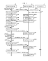
- FIG. 7 is a sequence diagram for illustrating the operation of a wireless audio system according to a second embodiment of the present invention.
- FIG. 8 is a schematic functional block diagram of a wireless speaker 1 a.
- FIG. 9 is a flow chart for illustrating the operation of the wireless speaker 1 a.
- FIG. 10 is a schematic functional block diagram of an audio controller 2 a.
- FIG. 11 is a flow chart for illustrating the operation of the audio controller 2 a.
- FIG. 1 is a schematic configuration diagram of a wireless audio system according to a first embodiment of the present invention.
- the wireless audio system includes a plurality of wireless speakers 1 - 1 to 1 - 3 (hereinafter may also simply be referred to as “wireless speaker(s) 1 ”) each having an ID attached thereto, an audio controller 2 , which is a portable terminal including a microphone, and a media server 3 and an access point 4 , which are connected to a network 5 . It is assumed that the wireless speakers 1 - 1 to 1 - 3 are installed in individual Rooms A to C, respectively.
- Each of the wireless speakers 1 is connected to the audio controller 2 and the media server 3 via the access point 4 , and acquires music data from the media server 3 and reproduces the music data for output in accordance with a reproduction instruction received from the audio controller 2 .
- the wireless speaker 1 sequentially measures the output volume levels of audio signals output from the wireless speaker 1 within a predetermined period, and sequentially receives the input volume levels of audio signals from the audio controller 2 .
- the wireless speaker 1 compares the latest input volume level received and the latest output volume level measured to determine whether a listener carrying the audio controller 2 has left the room in which this wireless speaker 1 is installed. When it is determined that the listener has left the room, the output of an audio signal is stopped.
- the audio controller 2 is also connected to the wireless speakers 1 and the media server 3 via the access point 4 , and transmits the reproduction instruction, which includes the specification of music data selected by a listener from among pieces of music data stored in the media server 3 , to one of the wireless speakers 1 that is the output destination of the music data.
- the audio controller 2 sequentially measures the input volume levels of audio signals input to the microphone within a predetermined period, and transmits the measured input volume levels to the wireless speaker 1 that is the output destination of the music data.
- FIG. 2 is a flow chart for illustrating the operation of the wireless audio system according to the first embodiment.
- the description given here takes as an example a case in which a listener carrying the audio controller 2 enjoys music with the use of the wireless speaker 1 - 1 installed in Room A.
- the audio controller 2 receives from the listener carrying the audio controller 2 and staying in Room A music selection operation, which involves the specification of music data to be reproduced and the specification of the ID of the wireless speaker 1 - 1 as the output destination of the music data (Step S 100 ), and multicasts a reproduction instruction in which the music data to be reproduced and the ID of the wireless speaker 1 - 1 are specified over the network 5 (Step S 101 ).
- the audio controller 2 also turns on the microphone included in the audio controller 2 (Step S 102 ).
- the wireless speaker 1 - 1 receives the reproduction instruction in which the ID of the wireless speaker 1 - 1 is specified over the network 5 , and transmits to the media server 3 a music data request in which the music data specified by the reproduction instruction is specified (Step S 103 ).
- the media server 3 receives the request, identifies the music data that is specified in the music data request received from the wireless speaker 1 - 1 from among pieces of music data stored in the media server 3 , and transmits the identified music data to the wireless speaker 1 - 1 (Step S 104 ).
- the wireless speaker 1 - 1 receives the music data from the media server 3 , and starts reproducing the music data as audio signals and outputting the reproduced audio signals (Step S 105 ).
- the wireless speaker 1 - 1 also starts measuring an output volume level Vout of audio signals that are output within a predetermined period T 2 (for example, 1 second) at a predetermined interval T 1 (for example, a 1-second interval) (Step S 106 ).
- the audio controller 2 detects that the audio signals output from the wireless speaker 1 - 1 are input to the microphone included in the audio controller 2 (Step S 107 ), and starts measuring an input volume level Vin of audio signals that are input to the microphone within the predetermined period T 2 at the predetermined interval T 1 (Step S 108 ). Each time the input volume level Vin is newly measured, the audio controller 2 multicasts an input volume level notification (Vin notification) in which the newly measured input volume level Vin and the ID of the wireless speaker 1 - 1 are specified over the network 5 (Step S 109 ).
- Vin notification input volume level notification
- the wireless speaker 1 - 1 receives the notification and starts receiving an input volume level notification in which the ID of the wireless speaker 1 - 1 is specified over the network 5 (Step S 110 ). Each time an input volume level notification is newly received, the wireless speaker 1 - 1 obtains a volume level ratio Vin/Vout, which indicates the proportion of the input volume level Vin that is included in the newly received input volume level notification to the output volume level Vout that is newly measured by the wireless speaker 1 - 1 , and monitors a change in the volume level ratio Vin/Vout (Step S 111 ).
- Step S 112 the listener carrying the audio controller 2 leaves Room A (Step S 112 ), thereby causing the input volume level Vin of an audio signal that is input to the microphone of the audio controller 2 to decrease.
- the volume level ratio Vin/Vout calculated by the wireless speaker 1 - 1 rapidly drops as a result.
- the wireless speaker 1 - 1 detects that the volume level ratio Vin/Vout has dropped by a predetermined value P (for example, 5 dB) or more within a predetermined period T 3 (for example, 4 seconds to 6 seconds) (Step S 113 ), and determines that the listener has left Room A.
- P for example, 5 dB
- T 3 for example, 4 seconds to 6 seconds
- the wireless speaker 1 - 1 then registers the value of a sound volume Vol of the wireless speaker 1 - 1 as resumption information, changes the value of the sound volume Vol to a zero value, and stops outputting an audio signal (Step S 114 ).
- the wireless speaker 1 - 1 subsequently waits for a predetermined time-out time T 4 (for example, 3 minutes) to elapse.
- the listener carrying the audio controller 2 reenters Room A (Step S 115 ).
- the audio controller 2 receives, from the listener, resumption operation, which involves the specification of the ID of the wireless speaker 1 - 1 (Step S 116 ), and multicasts a resumption instruction in which the ID of the wireless speaker 1 - 1 is specified over the network 5 (Step S 117 ).
- the wireless speaker 1 - 1 After the output of an audio signal is stopped and before the time-out time T 4 elapses, the wireless speaker 1 - 1 receives the resumption instruction in which the ID of the wireless speaker 1 - 1 is specified over the network 5 , changes the value of the sound volume Vol from the zero value to the value registered as the resumption information, and resumes the output of an audio signal (Step S 118 ).
- Step S 119 the listener carrying the audio controller 2 leaves Room A again (Step S 119 ), thereby causing the input volume level Vin of an audio signal that is input to the microphone of the audio controller 2 to decrease.
- the volume level ratio Vin/Vout calculated by the wireless speaker 1 - 1 rapidly drops as a result.
- the wireless speaker 1 - 1 detects that the volume level ratio Vin/Vout has dropped by the predetermined value P or more within the predetermined period T 3 (Step S 120 ), and determines that the listener has left Room A.
- the wireless speaker 1 - 1 registers the value of a sound volume Vol of the wireless speaker 1 - 1 as resumption information, changes the value of the sound volume Vol to a zero value, and stops outputting an audio signal (Step S 121 ).
- the wireless speaker 1 - 1 subsequently waits for the predetermined time-out time T 4 to elapse.
- the wireless speaker 1 - 1 detects time-out (Step S 122 ), stops the reproduction of music data as audio signals, and powers off (Step S 123 ).
- the wireless speaker 1 is described first.
- FIG. 3 is a schematic functional block diagram of the wireless speaker 1 .
- the functional configuration of the wireless speaker 1 illustrated in FIG. 3 is implemented by, for example, a CPU included in a computer along with a memory, an auxiliary storage device, which is a flash memory or the like, a wireless communication device, which is a wireless LAN adapter or the like, and a speaker by loading a predetermined program onto the memory from the auxiliary storage device and executing the program.
- the wireless speaker 1 includes speaker unit 10 , a wireless network interface unit 11 , an instruction reception unit 12 , a music data acquisition unit 13 , a music data storage unit 14 , a music data reproduction unit 15 , an output volume level measurement unit 16 , an input volume level reception unit 17 , an exit determination unit 18 , and a main control unit 19 .
- the wireless network interface unit 11 is an interface for, for example, communicating to/from the audio controller 2 and communicating to/from the media server 3 connected to the network 5 via the access point 4 .
- the instruction reception unit 12 receives various instructions to each of which the ID of its own wireless speaker 1 is attached from the audio controller 2 via the wireless network interface unit 11 .
- the music data acquisition unit 13 transmits a music data request including the specification of music data to be reproduced to the media server 3 via the wireless network interface unit 11 , and acquires the music data to be reproduced from the media server 3 .
- the music data storage unit 14 stores the music data acquired by the music data acquisition unit 13 from the media server 3 .
- the music data reproduction unit 15 reproduces music data stored in the music data storage unit 14 as audio signals, and outputs the audio signals from the speaker unit 10 .
- the output volume level measurement unit 16 measures, at the predetermined interval T 1 (for example, a 1-second interval), the output volume level Vout, which is an average of output volumes of audio signals that are output from the speaker unit 10 by the music data reproduction unit 15 within the predetermined period T 2 (for example, 1 second).
- the input volume level reception unit 17 receives via the wireless network interface unit 11 an input volume level notification, which is transmitted regularly from the audio controller 2 and which includes the ID of its own wireless speaker 1 .
- the exit determination unit 18 obtains, each time the input volume level reception unit 17 newly receives an input volume level notification that includes the ID of its own wireless speaker, the volume level ratio Vin/Vout, which indicates the proportion of the input volume level Vin included in the input volume level notification to the latest output volume level Vout measured by the output volume level measurement unit 16 . Based on a change in the volume level ratio Vin/Vout, the exit determination unit 18 determines whether the listener carrying the audio controller 2 has left the room in which its own wireless speaker 1 is installed.
- the main control unit 19 controls the units 10 to 18 of the wireless speaker 1 in an integrated manner.
- the main control unit 19 also controls the reproduction/output of music data by the music data reproduction unit 15 and the powering on/off based on the determination made in the exit determination unit 18 .
- FIG. 4 is a flow chart for illustrating the operation of the wireless speaker 1 . This flow is started when the instruction reception unit 12 receives a reproduction instruction to which the ID of its own wireless speaker 1 is attached from the audio controller 2 via the wireless network interface unit 11 .
- the instruction reception unit 12 hands over the received reproduction instruction to the main control unit 19 .
- the main control unit 19 receives the reproduction instruction, and notifies music data specified by the received reproduction instruction as data to be reproduced to the music data acquisition unit 13 .
- the music data acquisition unit 13 transmits a music data request in which the specification of the music data notified by the main control unit 19 is included to the media server 3 via the wireless network interface unit 11 (Step S 200 ).
- the music data acquisition unit 13 receives the music data from the media server 3 , and stores the received music data in the music data storage unit 14 (Step S 201 ).
- the music data acquisition unit 13 also notifies the main control unit 19 of the completion of the acquisition of the music data.
- the main control unit 19 receives the notification, and notifies the music data to be reproduced to the music data reproduction unit 15 .
- the music data reproduction unit 15 reads the music data to be reproduced out of the music data storage unit 14 , reproduces the read data as audio signals, and outputs the reproduced audio signals from the speaker unit 10 (Step S 202 ).
- the output volume level measurement unit 16 measures at the predetermined interval T 1 the output volume level Vout, which is an average of output volumes of audio signals that are output from the speaker unit 10 by the music data reproduction unit 15 within the predetermined period T 2 (Step S 203 ).
- the main control unit 19 ends this flow.
- the input volume level reception unit 17 receives via the wireless network interface unit 11 an input volume level notification (Vin notification), which is transmitted regularly from the audio controller 2 and which includes the ID of its own wireless speaker 1 (“YES ” in Step S 204 ), at a point preceding the end of the audio signal reproduction by the music data reproduction unit 15 (“NO” in Step S 205 ), the input volume level reception unit 17 hands over the input volume level Vin that is included in the input volume level notification to the exit determination unit 18 .
- Vin notification input volume level notification
- the exit determination unit 18 receives the input volume level Vin, and calculates and stores the volume level ratio Vin/Vout, which indicates the proportion of the input volume level Vin received from the input volume level reception unit 17 to the latest output volume level Vout measured by the output volume level measurement unit 16 (Step S 206 ).
- the exit determination unit 18 determines whether a volume level ratio Vin/Vout calculated at a point that goes back by the predetermined period T 3 (for example, 4 seconds to 6 seconds) is stored (Step S 207 ). When it is determined that a volume level ratio Vin/Vout calculated at a point that goes back by the predetermined period T 3 is not stored (“NO” in Step S 207 ), the flow returns to Step S 204 .
- T 3 for example, 4 seconds to 6 seconds
- Step S 207 When it is determined that a volume level ratio Vin/Vout calculated at a point that goes back by the predetermined period T 3 is stored (“YES” in Step S 207 ), on the other hand, the exit determination unit 18 compares the volume level ratio Vin/Vout calculated at a point that goes back by the predetermined period T 3 and the newly calculated volume level ratio Vin/Vout to determine whether the newly calculated volume level ratio Vin/Vout is lower than the volume level ratio Vin/Vout calculated at a point that goes back by the predetermined period T 3 by the predetermined value P (for example, 5 dB) or more (Step S 208 ).
- P for example, 5 dB
- Step S 208 When the newly calculated volume level ratio Vin/Vout is not lower than the volume level ratio Vin/Vout calculated at a point that goes back by the predetermined period T 3 by the predetermined value P or more (“NO” in Step S 208 ), the flow returns to Step S 204 .
- the exit determination unit 18 notifies the main control unit 19 of that fact.
- the main control unit 19 registers the value of the sound volume Vol of the music data reproduction unit 15 as resumption information (Step S 209 ), changes the sound volume Vol of the music data reproduction unit 15 to a zero value, and stops the output of an audio signal from the speaker unit 10 (Step S 210 ).
- the output volume level measurement unit 16 may stop the measurement of the output volume level Vout at this point.
- the main control unit 19 waits for the reception of a resumption instruction from the audio controller 2 via the wireless network interface unit 11 and the instruction reception unit 12 (Step S 211 ).
- the instruction reception unit 12 receives a resumption instruction in which the ID of its own wireless speaker 1 is specified from the audio controller 2 via the wireless network interface unit 11 (“YES” in Step S 211 ), and notifies the resumption instruction to the main control unit 19 .
- the main control unit 19 receives the resumption instruction, changes the sound volume Vol of the music data reproduction unit 15 from the zero value to the value registered as the resumption information, and resumes the output of an audio signal from the speaker unit 10 (Step S 212 ).
- the output volume level measurement unit 16 resumes the measurement of the output volume level Vout. The flow then returns to Step S 204 .
- the main control unit 19 causes the music data reproduction unit 15 to stop the reproduction of audio signals from music data, and then turns off the main power (Step S 214 ) to end this flow.
- the main control unit 19 ends this flow also when the audio signal reproduction by the music data reproduction unit 15 is finished (“YES” in Step S 215 ) before the predetermined time-out time T 4 elapses (“NO” in Step S 213 ) without receiving a resumption instruction from the audio controller 2 via the wireless network interface unit 11 and the instruction reception unit 12 (“NO” in Step S 211 ).
- the audio controller 2 is described next.
- FIG. 5 is a schematic functional block diagram of the audio controller 2 .
- the functional configuration of the audio controller 2 illustrated in FIG. 5 is implemented by, for example, a CPU included in a portable computer, which is a smartphone, a tablet PC, or the like, along with a memory, an auxiliary storage device, which is a flash memory or the like, a touch panel, a display, an input/output device, which is a pointing device or the like, a wireless communication device, which is a wireless LAN adapter or the like, and a microphone by loading a predetermined program onto the memory from the auxiliary storage device and executing the program.
- the audio controller 2 includes a microphone unit 20 , a wireless network interface unit 21 , a graphical user interface unit 22 , a reproduction instruction transmission unit 23 , a resumption instruction transmission unit 24 , an input volume level measurement unit 25 , an input volume level notification unit 26 , and a main control unit 27 .
- the wireless network interface unit 21 is an interface for communicating to/from the wireless speaker 1 via the access point 4 .
- the graphical user interface unit 22 is an interface for, for example, displaying information and receiving various operations from the user.
- the reproduction instruction transmission unit 23 multicasts, from the wireless network interface unit 21 , a reproduction instruction in which music data to be reproduced and the ID of one of the wireless speakers 1 that is the output destination of the music data are specified.
- the resumption instruction transmission unit 24 multicasts a resumption instruction in which the ID of one of the wireless speakers 1 that is the output destination of the music data is specified from the wireless network interface unit 21 .
- the input volume level measurement unit 25 measures, at the predetermined interval T 1 (for example, a 1-second interval), the input volume level Vin, which is an average of input volumes of audio signals that are input to the microphone unit 20 within the predetermined period T 2 (for example, 1 second).
- the input volume level notification unit 26 Each time the input volume level measurement unit 25 measures the input volume level Vin, the input volume level notification unit 26 multicasts an input volume level notification including the measured input volume level Vin and the specification of the ID of one of the wireless speakers 1 that is the output destination of music data from the wireless network interface unit 21 .
- the main control unit 27 controls the units 20 to 26 of the audio controller 2 in an integrated manner.
- FIG. 6 is a flow chart for illustrating the operation of the audio controller 2 . This flow is started when the main control unit 27 receives music selection operation, which involves the specification of music data to be reproduced and the specification of the ID of one of the wireless speakers 1 that is the output destination of the music data, from the listener via the graphical user interface unit 22 .
- music selection operation which involves the specification of music data to be reproduced and the specification of the ID of one of the wireless speakers 1 that is the output destination of the music data, from the listener via the graphical user interface unit 22 .
- the main control unit 27 first hands over the music data to be reproduced and the ID of the wireless speaker 1 that is the output destination of the music data to the reproduction instruction transmission unit 23 .
- the reproduction instruction transmission unit 23 receives the music data and the ID, and multicasts the reproduction instruction in which the music data to be reproduced and the ID of the wireless speaker 1 that is the output destination of the music data are specified from the wireless network interface unit 21 (Step S 300 ).
- the main control unit 27 next turns on the microphone unit 20 (Step S 301 ) and waits for an input of an audio signal to the microphone unit 20 (Step S 302 ).
- the main control unit 27 instructs the input volume level measurement unit 25 to start measuring the input volume level Vin, and instructs the input volume level notification unit 26 to start transmitting an input volume level notification by notifying the ID of the wireless speaker 1 that is the output destination of the music data to the input volume level notification unit 26 .
- the input volume level measurement unit 25 responds to the instruction by measuring, at the predetermined interval T 1 , the input volume level Vin, which is an average of input volumes of audio signals that are input to the microphone unit 20 within the predetermined period T 2 .
- the input volume level notification unit 26 multicasts an input volume level notification including the measured input volume level Vin and the specification of the ID of the wireless speaker 1 that is the output destination of the music data from the wireless network interface unit 21 (Step S 303 ).
- the main control unit 27 subsequently receives resumption operation, which involves the specification of the ID of the wireless speaker 1 that is the output destination of the music data, from the listener via the graphical user interface unit (“YES” in Step S 304 ), and hands over the ID of this output destination wireless speaker 1 to the resumption instruction transmission unit 24 .
- the resumption instruction transmission unit 24 receives the ID, and multicasts a resumption instruction in which the ID of the output destination wireless speaker 1 is specified from the wireless network interface unit 21 (Step S 305 ).
- the main control unit 27 instructs the input volume level measurement unit 25 to end the measurement of the input volume level Vin, and instructs the input volume level notification unit 26 to end the transmission of an input volume level notification.
- the input volume level measurement unit 25 ends the measurement of the input volume level Vin in response to the instruction.
- the input volume level notification unit 26 ends the multicasting of an input volume level notification (Step S 307 ).
- the main control unit 27 then turns off the microphone unit 20 (Step S 308 ), and ends this flow.
- the output volume level Vout of audio signals output from the speaker unit 10 of one of the wireless speakers 1 and the input volume level Vin of audio signals input to the microphone unit 20 of the audio controller 2 are compared to determine, from the ratio of the two volume levels, namely, Vin/Vout, whether a listener carrying the audio controller 2 has left the room in which the wireless speaker 1 is installed.
- the output of an audio signal from the wireless speaker 1 is stopped.
- the output of an audio signal can thus be automatically stopped when a listener leaves a room in which the wireless speaker 1 is currently outputting an audio signal without stopping the output of an audio signal. Power consumption can accordingly be reduced by preventing a useless output of an audio signal.
- the wireless speakers 1 when one of the wireless speakers 1 receives a resumption instruction from the audio controller 2 in a period that follows the stop of the output of an audio signal and that precedes the elapse of the predetermined time-out time T 4 , the sound volume Vol is returned to a state prior to the stop of the output of an output signal to resume the output of an audio signal.
- the reproduction of music data as audio signals is stopped and the wireless speaker 1 is powered off.
- a listener carrying the audio controller 2 has left a room in which one of the wireless speakers 1 is installed when the volume level ratio Vin/Vout drops by the predetermined value P or more within the predetermined period T 3 (Step S 113 and Step S 120 of FIG. 2 and Step S 208 of FIG. 4 ).
- the present invention is not limited to the first embodiment in which the output volume level Vout of audio signals output from the speaker unit 10 of one of the wireless speakers 1 and the input volume level Vin of audio signals input to the microphone unit 20 of the audio controller 2 are compared to determine, from the ratio of the two volume levels, namely, Vin/Vout, whether a listener carrying the audio controller 2 has left the room in which the wireless speaker 1 is installed.
- the present invention can be carried out in any mode as long as whether a listener carrying the audio controller 2 is away from the vicinity of one of the wireless speakers 1 can be determined based on the result of a comparison between an output characteristic of an audio signal output from the speaker unit 10 of the wireless speaker 1 and an input characteristic of an audio signal input to the microphone unit 20 of the audio controller 2 .
- each of the wireless speakers 1 measures at the predetermined interval T 1 the output waveforms of audio signals output from the speaker unit 10 within the predetermined period T 2
- the audio controller 2 measures at the predetermined interval T 1 the input waveforms of audio signals input to the microphone unit 20 within the predetermined period T 2 to transmit the input waveforms to the wireless speaker 1 .
- the wireless speaker 1 compares the latest output waveform measured and the latest input waveform received from the audio controller 2 , and determines whether a listener carrying the audio controller 2 is away from the vicinity of the wireless speaker 1 based on whether a delay time of the input waveform with respect to the output waveform (a phase difference) is equal to more than a predetermined length of time.
- a wireless audio system according to a second embodiment of the present invention differs from the wireless audio system according to the first embodiment, which is illustrated in FIG. 1 , in that wireless speakers 1 a - 1 to 1 a - 3 (hereinafter may also simply be referred to as “wireless speaker (s) 1 a ”) are used in place of the wireless speakers 1 - 1 to 1 - 3 , and in that an audio controller 2 a is used in place of the audio controller 2 . The rest are the same as in the wireless audio system of the first embodiment illustrated in FIG. 1 .
- Each of the wireless speakers 1 a is connected to the audio controller 2 a and the media server 3 via the access point 4 , and acquires music data from the media server 3 and reproduces the music data for output in accordance with a reproduction instruction received from the audio controller 2 a .
- the wireless speaker 1 a sequentially measures the output volume levels of audio signals output from the wireless speaker 1 a within a predetermined period, and transmits the output volume levels to the audio controller 2 a , which is the sender of the reproduction instruction.
- the wireless speaker 1 a stops outputting an audio signal by following an output stop instruction issued by the audio controller 2 a.
- the audio controller 2 a is also connected to the wireless speakers 1 a and the media server 3 via the access point 4 , and transmits the reproduction instruction, which includes the specification of music data selected by a listener from among pieces of music data stored in the media server 3 , to one of the wireless speakers 1 a that is the output destination of the music data.
- the audio controller 2 a sequentially measures the input volume levels of audio signals input to the microphone within a predetermined period, and sequentially receives the output volume levels of audio signals from the wireless speaker 1 a .
- the audio controller 2 a compares the input volume levels and the output volume levels to determine whether a listener carrying the audio controller 2 has left the room in which the wireless speaker 1 a is installed. When it is determined that the listener has left the room in which the wireless speaker 1 a is installed, the audio controller 2 a transmits an audio signal output stop instruction to the wireless speaker 1 a that is the output destination of the music data.
- FIG. 7 is a flow chart for illustrating the operation of the wireless audio system according to the second embodiment.
- the description given here takes as an example a case in which a listener carrying the audio controller 2 a enjoys music with the use of the wireless speaker 1 a - 1 installed in Room A.
- the audio controller 2 a receives from the listener carrying the audio controller 2 a and staying in Room A music selection operation, which involves the specification of music data to be reproduced and the specification of the ID of the wireless speaker 1 a - 1 as the output destination of the music data (Step S 150 ), and multicasts a reproduction instruction in which the music data to be reproduced and the ID of the wireless speaker 1 a - 1 are specified over the network 5 (Step S 151 ).
- the audio controller 2 a also turns on the microphone included in the audio controller 2 a (Step S 152 ).
- the wireless speaker 1 a - 1 receives the reproduction instruction in which the ID of the wireless speaker 1 a - 1 is specified over the network 5 , and transmits to the media server 3 a music data request in which the music data specified by the reproduction instruction is specified (Step S 153 ).
- the media server 3 receives the request, identifies the music data that is specified in the music data request received from the wireless speaker 1 a - 1 from among pieces of music data stored in the media server 3 , and transmits the identified music data to the wireless speaker 1 a - 1 (Step S 154 ).
- the wireless speaker 1 a - 1 receives the music data from the media server 3 , reproduces the music data as audio signals, and starts outputting the reproduced audio signals (Step S 155 ).
- the wireless speaker 1 a - 1 also starts measuring an output volume level Vout of audio signals that are output within the predetermined period T 2 (for example, 1 second) at the predetermined interval T 1 (for example, a 1-second interval) (Step S 156 ). Each time the output volume level Vout is newly measured, the wireless speaker 1 a - 1 transmits an output volume level notification (Vout notification) in which the newly measured output volume level Vout is included to the audio controller 2 a , which is the sender of the reproduction instruction (Step S 157 ).
- Vout notification output volume level notification
- the audio controller 2 a detects that an audio signal output from the wireless speaker 1 a - 1 is input to the microphone, which is included in the audio controller 2 a (Step S 158 ), and starts measuring the input volume level Vin of audio signals input to the microphone within the predetermined period T 2 at the predetermined interval T 1 (Step S 159 ).
- the audio controller 2 a also starts receiving an output volume level notification from the wireless speaker 1 - a (Step S 160 ).
- the audio controller 2 a obtains the volume level ratio Vin/Vout, which indicates the proportion of the input volume level Vin newly measured by the audio controller 2 a to the output volume level Vout included in the newly received output volume level notification, and monitors a change in the volume level ratio Vin/Vout (Step S 161 ).
- Step S 162 the listener carrying the audio controller 2 a leaves Room A (Step S 162 ), thereby causing the input volume level Vin of an audio signal that is input to the microphone of the audio controller 2 a to decrease.
- the volume level ratio Vin/Vout calculated by the audio controller 2 a rapidly drops as a result.
- the audio controller 2 a detects that the volume level ratio Vin/Vout has dropped by the predetermined value P (for example, 5 dB) or more within the predetermined period T 3 (for example, 4 seconds to 6 seconds) (Step S 163 ), and determines that the listener has left Room A.
- P for example, 5 dB
- T 3 for example, 4 seconds to 6 seconds
- the audio controller 2 a multicasts an output stop instruction specifying the ID of the wireless speaker 1 a - 1 , which is the output destination of the music data (Step S 164 ).
- the audio controller 2 a subsequently waits for the predetermined time-out time T 4 (for example, 3 minutes) to elapse.
- the wireless speaker 1 a - 1 receives the output stop instruction in which the ID of the wireless speaker 1 a - 1 is specified from the audio controller 2 a , registers the value of the sound volume Vol of the wireless speaker 1 a - 1 as resumption information, changes the sound volume Vol to a zero value, and stops outputting an audio signal (Step S 165 ).
- the wireless speaker 1 a - 1 may stop the measurement of the output volume level Vout at this point.
- Step S 166 the listener carrying the audio controller 2 a reenters Room. A
- the audio controller 2 a receives, from the listener, resumption operation, which involves the specification of the ID of the wireless speaker 1 a - 1 (Step S 167 ), and multicasts a resumption instruction in which the ID of the wireless speaker 1 a - 1 is specified over the network 5 (Step S 168 ).
- the wireless speaker 1 a - 1 receives the resumption instruction in which the ID of the wireless speaker 1 a - 1 is specified from the audio controller 2 a , changes the value of the sound volume Vol from the zero value to the value registered as the resumption information, and resumes the output of an audio signal (Step S 169 ). In the case where the measurement of the volume level Vout has been stopped during the period in which the output of an audio signal is stopped, the wireless speaker 1 a - 1 resumes the measurement of the output volume level Vout.
- Step S 170 the listener carrying the audio controller 2 a leaves Room A again (Step S 170 ), thereby causing the input volume level Vin of an audio signal that is input to the microphone of the audio controller 2 a to decrease.
- the volume level ratio Vin/Vout calculated by the audio controller 2 a rapidly drops as a result.
- the audio controller 2 a detects that the volume level ratio Vin/Vout has dropped by the predetermined value P or more within the predetermined period T 3 (Step S 171 ), and determines that the listener has left Room A.
- the audio controller 2 a multicasts an output stop instruction specifying the ID of the wireless speaker 1 a - 1 , which is the output destination of the music data (Step S 172 ).
- the wireless speaker 1 a - 1 may stop the measurement of the output volume level Vout at this point.
- the audio controller 2 a subsequently waits for the predetermined time-out time T 4 (for example, 3 minutes) to elapse.
- the wireless speaker 1 a - 1 receives the output stop instruction in which the ID of the wireless speaker 1 a - 1 is specified from the audio controller 2 a , registers the value of the sound volume Vol of the wireless speaker 1 a - 1 as resumption information, changes the sound volume Vol to a zero value, and stops outputting an audio signal (Step S 173 ).
- the audio controller 2 a multicasts a power-off instruction in which the ID of the wireless speaker 1 a - 1 is specified over the network 5 (Step S 175 ).
- the wireless speaker 1 a - 1 receives the power-off instruction in which the ID of the wireless speaker 1 a - 1 is specified from the audio controller 2 a , stops the reproduction of the music data as audio signals, and powers off (Step S 176 ).
- the description given next is about details of the wireless speaker 1 a and the audio controller 2 a of the wireless audio system according to the second embodiment.
- the wireless speaker 1 a is described first.
- FIG. 8 is a schematic functional block diagram of the wireless speaker 1 a .
- the functional configuration of the wireless speaker 1 a illustrated in FIG. 8 is implemented by, for example, a CPU included in a computer along with a memory, an auxiliary storage device, which is a flash memory or the like, a wireless communication device, which is a wireless LAN adapter or the like, and a speaker by loading a predetermined program onto the memory from the auxiliary storage device and executing the program.
- the wireless speaker la includes the speaker unit 10 , the wireless network interface unit 11 , the instruction reception unit 12 , the music data acquisition unit 13 , the music data storage unit 14 , the music data reproduction unit 15 , the output volume level measurement unit 16 , an output volume level notification unit 30 , and a main control unit 31 .
- the units in FIG. 8 that have the same functions as those of the wireless speaker 1 in the first embodiment illustrated in FIG. 3 are denoted by the same reference symbols.
- the output volume level notification unit 30 transmits, each time the output volume level measurement unit 16 measures the output volume level Vout, an output volume level notification including the measured output volume level Vout via the wireless network interface unit 11 to the audio controller 2 a , which is the sender of a reproduction instruction issued to music data that is currently being reproduced as audio signals by the music data reproduction unit 15 .
- the main control unit 31 controls the units 10 to 16 and 30 of the wireless speaker 1 a in an integrated manner.
- the main control unit 31 also controls the reproduction/output of music data by the music data reproduction unit 15 and the powering on/off based on instructions received from the audio controller 2 a via the instruction reception unit 12 .
- FIG. 9 is a flow chart for illustrating the operation of the wireless speaker 1 a . This flow is started when the instruction reception unit 12 receives a reproduction instruction to which the ID of its own wireless speaker 1 a is attached from the audio controller 2 a via the wireless network interface unit 11 .
- the instruction reception unit 12 hands over the received reproduction instruction to the main control unit 31 .
- the main control unit 31 receives the reproduction instruction, notifies the address of the audio controller 2 a , which is the sender of the reproduction instruction, to the output volume level notification unit 30 , and notifies music data specified by the received reproduction instruction as data to be reproduced to the music data acquisition unit 13 .
- the music data acquisition unit 13 transmits a music data request in which the specification of the music data notified by the main control unit 31 is included to the media server 3 via the wireless network interface unit 11 (Step S 250 ).
- the music data acquisition unit 13 receives the music data from the media server 3 , and stores the received music data in the music data storage unit 14 (Step S 251 ).
- the music data acquisition unit 13 also notifies the main control unit 31 of the completion of the acquisition of the music data.
- the main control unit 31 receives the notification, and notifies the music data to be reproduced to the music data reproduction unit 15 .
- the music data reproduction unit 15 reads the music data to be reproduced out of the music data storage unit 14 , reproduces the read data as audio signals, and outputs the reproduced audio signals from the speaker unit 10 (Step S 252 ).
- the output volume level measurement unit 16 measures at the predetermined interval T 1 the output volume level Vout, which is an average of output volumes of audio signals that are output from the speaker unit 10 by the music data reproduction unit 15 within the predetermined period T 2 .
- the output volume level notification unit 30 transmits an output volume level notification including the measured output volume level Vout via the wireless network interface unit 11 to the audio controller 2 a , which is identified from the address notified by the main control unit 31 (Step S 253 ).
- the main control unit 31 waits for the reception of an output stop instruction from the audio controller 2 a via the wireless network interface unit 11 and the instruction reception unit 12 (Step S 254 ).
- the instruction reception unit 12 receives an output stop instruction to which the ID of its own wireless speaker 1 a is attached from the audio controller 2 a via the wireless network interface unit 11 (“YES” in Step S 254 ), and hands over the received output stop instruction to the main control unit 31 .
- the main control unit 31 receives the output stop instruction, registers the value of the sound volume Vol of the music data reproduction unit 15 as resumption information (Step S 255 ), changes the sound volume Vol of the music data reproduction unit 15 to a zero value, and stops the output of an audio signal from the speaker unit 10 (Step S 256 ).
- the output volume level measurement unit 16 may stop the measurement of the output volume level Vout at this point.
- Step S 262 the main control unit 31 waits for the reception of a resumption instruction or a power-off instruction from the audio controller 2 a via the wireless network interface unit 11 and the instruction reception unit 12 (Step S 258 and Step S 260 ).
- Step S 258 When receiving a resumption instruction to which the ID of its own wireless speaker 1 a is attached from the audio controller 2 a via the wireless network interface unit 11 (“YES” in Step S 258 ), the instruction reception unit 12 hands over the resumption instruction to the control unit 31 .
- the main control unit 31 receives the resumption instruction, changes the sound volume Vol of the music data reproduction unit 15 from the zero value to the value registered as the resumption information, and resumes the output of an audio signal from the speaker unit 10 (Step S 259 ).
- the output volume level measurement unit 16 resumes the measurement of the output volume level Vout. The flow then returns to Step S 254 .
- Step S 260 When receiving a power-off instruction to which the ID of its own wireless speaker 1 a is attached from the audio controller 2 a via the wireless network interface unit 11 (“YES” in Step S 260 ), the instruction reception unit 12 hands over the power-off instruction to the main control unit 31 .
- the main control unit 31 receives the power-off instruction, causes the music data reproduction unit 15 to stop the reproduction of the music data as audio signals, and then turns off the main power (Step S 261 ) to end this flow.
- the main control unit 31 ends this flow also when the audio signal reproduction by the music data reproduction unit 15 is finished (“YES” in Step S 257 or “YES” in Step S 262 ).
- the audio controller 2 a is described next.
- FIG. 10 is a schematic functional block diagram of the audio controller 2 a .
- the functional configuration of the audio controller 2 a illustrated in FIG. 10 is implemented by, for example, a CPU included in a portable computer, which is a smartphone, a tablet PC, or the like, along with a memory, an auxiliary storage device, which is a flash memory or the like, a touch panel, a display, an input/output device, which is a pointing device or the like, a wireless communication device, which is a wireless LAN adapter or the like, and a microphone by loading a predetermined program onto the memory from the auxiliary storage device and executing the program.
- a CPU included in a portable computer which is a smartphone, a tablet PC, or the like
- a memory an auxiliary storage device, which is a flash memory or the like, a touch panel, a display, an input/output device, which is a pointing device or the like, a wireless communication device, which is a wireless LAN adapter or the like,
- the audio controller 2 a includes the microphone unit 20 , the wireless network interface unit 21 , the graphical user interface unit 22 , the reproduction instruction transmission unit 23 , the resumption instruction transmission unit 24 , the input volume level measurement unit 25 , an output stop instruction transmission unit 40 , a power-off instruction transmission unit 41 , an output volume level reception unit 42 , an exit determination unit 43 , and a main control unit 44 .
- the units in FIG. 10 that have the same functions as those of the audio controller 2 in the first embodiment illustrated in FIG. 5 are denoted by the same reference symbols.
- the output stop instruction transmission unit 40 multicasts an output stop instruction including the specification of the ID of one of the wireless speakers 1 a that is the output destination of music data from the wireless network interface unit 21 .
- the power-off instruction transmission unit 41 multicasts a power-off instruction including the specification of the ID of one of the wireless speakers 1 a that is the output destination of music data from the wireless network interface unit 21 .
- the output volume level reception unit 42 receives via the wireless network interface unit 21 an output volume level notification, which is transmitted regularly from each of the wireless speakers 1 a.
- the exit determination unit 43 obtains, each time the output volume level reception unit 42 newly receives an output volume level notification, the volume level ratio Vin/Vout, which indicates the proportion of the latest input volume level Vin measured by the input volume level measurement unit 25 to the output volume level Vout included in the received output volume level notification. Based on a change in the volume level ratio Vin/Vout, the exit determination unit 43 determines whether a listener carrying the audio controller 2 a has left the room in which one of the wireless speakers 1 a that is the output destination of music data is installed.
- the main control unit 44 controls the units 20 to 25 and 40 to 43 of the audio controller 2 a in an integrated manner.
- FIG. 11 is a flow chart for illustrating the operation of the audio controller 2 a . This flow is started when the main control unit 44 receives music selection operation, which involves the specification of music data to be reproduced and the specification of the ID of one of the wireless speakers 1 a that is the output destination of the music data, from the listener via the graphical user interface unit 22 .
- music selection operation which involves the specification of music data to be reproduced and the specification of the ID of one of the wireless speakers 1 a that is the output destination of the music data, from the listener via the graphical user interface unit 22 .
- the main control unit 44 first hands over the music data to be reproduced and the ID of the wireless speaker 1 a that is the output destination of the music data to the reproduction instruction transmission unit 23 .
- the reproduction instruction transmission unit 23 receives the music data and the ID, and multicasts a reproduction instruction in which the music data to be reproduced and the ID of the wireless speaker 1 a that is the output destination of the music data are specified from the wireless network interface unit 21 (Step S 350 ).
- the main control unit 44 next turns on the microphone unit 20 (Step S 351 ) and waits for an input of an audio signal to the microphone unit 20 (Step S 352 ).
- the main control unit 44 instructs the input volume level measurement unit 25 to start measuring the input volume level Vin.
- the input volume level measurement unit 25 responds to the instruction by measuring, at the predetermined interval T 1 , the input volume level Vin, which is an average of input volumes of audio signals that are input to the microphone unit 20 within the predetermined period T 2 (Step S 353 ).
- the output volume level reception unit 42 receives an output volume level notification (Vout notification), which is transmitted regularly from the wireless speaker 1 a , via the wireless network interface unit 21 (“YES” in Step S 354 ), and hands over the output volume level Vout included in the output volume level notification to the exit determination unit 43 .
- the exit determination unit 43 receives the output volume level Vout, and calculates and stores the volume level ratio Vin/Vout, which indicates the proportion of the latest input volume level Vin measured by the input volume level measurement unit 25 to the output volume level Vout received from the output volume level reception unit 42 (Step S 355 ).
- the exit determination unit 43 determines whether a volume level ratio Vin/Vout calculated at a point that goes back by the predetermined period T 3 (for example, 4 seconds to 6 seconds) is stored (Step S 356 ). When it is determined that a volume level ratio Vin/Vout calculated at a point that goes back by the predetermined period T 3 is not stored (“NO” in Step S 356 ), the flow returns to Step S 354 .
- T 3 for example, 4 seconds to 6 seconds
- the exit determination unit 43 compares the volume level ratio Vin/Vout calculated at a point that goes back by the predetermined period T 3 and the newly calculated volume level ratio Vin/Vout to determine whether the newly calculated volume level ratio Vin/Vout is lower than the volume level ratio Vin/Vout calculated at a point that goes back by the predetermined period T 3 by the predetermined value P (for example, 5 dB) or more (Step S 357 ).
- Step S 357 When the newly calculated volume level ratio Vin/Vout is not lower than the volume level ratio Vin/Vout calculated at a point that goes back by the predetermined period T 3 by the predetermined value P or more (“NO” in Step S 357 ), the flow returns to Step S 354 .
- the exit determination unit 43 notifies the main control unit 44 of that fact.
- the main control unit 44 notifies the ID of the wireless speaker 1 a that is the output destination of the music data to the output stop instruction transmission unit 40 .
- the output stop instruction transmission unit 40 multicasts an output stop instruction in which the ID of the output destination wireless speaker 1 a is specified from the wireless network interface unit 21 (Step S 358 ).
- the input volume level measurement unit 25 may stop the measurement of the input volume level Vin at this point.
- Step S 361 the main control unit 44 waits for the reception of resumption operation from the listener via the graphical user interface unit 22 (Step S 359 ).
- the main control unit 44 subsequently receives resumption operation from the listener via the graphical user interface unit 22 (“YES” in Step S 359 ), and notifies the ID of the wireless speaker 1 a that is the output destination of the music data to the resumption instruction transmission unit 24 .
- the resumption instruction transmission unit 24 multicasts a resumption instruction in which the ID of the wireless speaker 1 a that is the output destination of the music data is specified from the wireless network interface unit 21 (Step S 360 ).
- the input volume level measurement unit 25 resumes the measurement of the input volume level Vin. The flow then returns to Step S 354 .
- the main control unit 44 When the time runs out with the elapse of the time-out time T 4 (“YES” in Step S 361 ) without receiving resumption operation from the listener (“NO” in Step S 359 ), on the other hand, the main control unit 44 notifies the ID of the wireless speaker 1 a that is the output destination of the music data to the power-off instruction transmission unit 41 .
- the power-off instruction transmission unit 41 multicasts a power-off instruction in which the ID of the output destination wireless speaker 1 a is specified from the wireless network interface unit 21 (Step S 362 ).
- the main control unit 44 then instructs the input volume level measurement unit 25 to end the measurement of the input volume level Vin.
- the input volume level measurement unit 25 ends the measurement of the input volume level Vin in response to the instruction (Step S 363 ).
- the main control unit 44 then turns off the microphone unit 20 (Step S 364 ), and ends this flow.
- Step S 365 When remote control ending operation for ending the remote control of the relevant wireless speaker 1 a is received from the listener via the graphical user interface unit 22 (“YES” in Step S 365 ), the main control unit 44 instructs the input volume level measurement unit 25 to end the measurement of the input volume level Vin.
- the input volume level measurement unit 25 ends the measurement of the input volume level Vin in response to the instruction (Step S 363 ).
- the main control unit 44 then turns off the microphone unit 20 (Step S 364 ), and ends this flow.
- the output volume level Vout of audio signals output from the speaker unit 10 of one of the wireless speakers 1 a and the input volume level Vin of audio signals input to the microphone unit 20 of the audio controller 2 a are compared to determine, from the ratio of the two volume levels, namely, Vin/Vout, whether a listener carrying the audio controller 2 a has left the room in which the wireless speaker 1 a is installed.
- the output of an audio signal from the wireless speaker 1 a is stopped.
- the output of an audio signal can thus be automatically stopped when a listener leaves a room in which the wireless speaker 1 a is currently outputting an audio signal without stopping the output of an audio signal. Power consumption can accordingly be reduced by preventing a useless output of an audio signal.
- the audio controller 2 a in the second embodiment transmits a resumption instruction for causing one of the wireless speakers 1 a to resume the output of an audio signal when receiving resumption operation from the listener in a period that follows the transmission of an output stop instruction for causing the wireless speaker 1 a to stop the output of an audio signal and that precedes the elapse of the predetermined time-out time T 4 .
- the audio controller 2 a transmits a power-off instruction for causing the wireless speaker 1 a to stop the reproduction of music data as audio signals and to power off.
- the output volume level Vout of audio signals output from the speaker unit 10 of one of the wireless speakers 1 a and the input volume level Vin of audio signals input to the microphone unit 20 of the audio controller 2 a are compared to determine, from the ratio of the two volume levels, namely, Vin/Vout, whether a listener carrying the audio controller 2 a has left the room in which the wireless speaker 1 a is installed.
- the present invention is not limited thereto.
- the present invention can be carried out in any mode as long as whether a listener carrying the audio controller 2 a is away from the vicinity of one of the wireless speakers 1 a can be determined based on the result of a comparison between an output characteristic of an audio signal output from the speaker unit 10 of the wireless speaker 1 a and an input characteristic of an audio signal input to the microphone unit 20 of the audio controller 2 a.
- each of the wireless speakers 1 a measures at the predetermined interval T 1 the output waveforms of audio signals output from the speaker unit 10 within the predetermined period T 2 to transmit the output waveforms to the audio controller 2 a
- the audio controller 2 a measures at the predetermined interval T 1 the input waveforms of audio signals input to the microphone unit 20 within the predetermined period T 2 .
- the audio controller 2 a compares the latest input waveform measured and the latest output waveform received from the wireless speaker 1 a , and determines whether a listener carrying the audio controller 2 a is away from the vicinity of the wireless speaker 1 a based on whether a delay time of the input waveform with respect to the output waveform (a phase difference) is equal to more than a predetermined length of time.
- the multicast transmission may be replaced with unicast transmission when the audio controller 2 or 2 a is aware of the address of each wireless speaker 1 or each wireless speaker 1 a.
- the audio controller 2 or 2 a in the embodiments described above is connected to the wireless speakers 1 or the wireless speakers 1 a via the access point 4 and the network 5 .
- the present invention is not limited thereto.
- the audio controller 2 or 2 a and the wireless speakers 1 or the wireless speakers 1 a may be connected directly by a wireless network through an ad-hoc mode of wireless LAN, Bluetooth (trademark), or other types of short-distance wireless communication.
- the media server 3 is connected to the network 5 , but the media server 3 may be connected to a wireless network.
- the media server 3 may be built into the audio controller 2 or 2 a , or into any one of the wireless speakers 1 or wireless speakers 1 a .
- the wireless speaker 1 or 1 a acquires music data from the audio controller 2 or 2 a .
- another wireless speaker 1 or 1 a acquires music data from the wireless speaker 1 or 1 a into which the media server 3 is built.
Landscapes
- Engineering & Computer Science (AREA)
- Physics & Mathematics (AREA)
- Acoustics & Sound (AREA)
- Signal Processing (AREA)
- Theoretical Computer Science (AREA)
- Health & Medical Sciences (AREA)
- General Health & Medical Sciences (AREA)
- Otolaryngology (AREA)
- Audiology, Speech & Language Pathology (AREA)
- Human Computer Interaction (AREA)
- General Engineering & Computer Science (AREA)
- General Physics & Mathematics (AREA)
- Multimedia (AREA)
- Circuit For Audible Band Transducer (AREA)
- Details Of Audible-Bandwidth Transducers (AREA)
Applications Claiming Priority (3)
| Application Number | Priority Date | Filing Date | Title |
|---|---|---|---|
| JP2015204130A JP6632855B2 (ja) | 2015-10-15 | 2015-10-15 | ワイヤレススピーカ、コントローラ、ワイヤレスオーディオシステム、およびコンピュータで読み取り可能なプログラム |
| JP2015-204130 | 2015-10-15 | ||
| PCT/JP2016/076849 WO2017064964A1 (ja) | 2015-10-15 | 2016-09-12 | ワイヤレススピーカ、コントローラ、ワイヤレスオーディオシステム、およびコンピュータで読み取り可能なプログラム |
Publications (1)
| Publication Number | Publication Date |
|---|---|
| US20180302716A1 true US20180302716A1 (en) | 2018-10-18 |
Family
ID=58517166
Family Applications (1)
| Application Number | Title | Priority Date | Filing Date |
|---|---|---|---|
| US15/767,744 Abandoned US20180302716A1 (en) | 2015-10-15 | 2016-09-12 | Wireless speaker, controller, wireless audio system, and computer-readable program |
Country Status (4)
| Country | Link |
|---|---|
| US (1) | US20180302716A1 (enExample) |
| EP (1) | EP3364665B1 (enExample) |
| JP (1) | JP6632855B2 (enExample) |
| WO (1) | WO2017064964A1 (enExample) |
Cited By (4)
| Publication number | Priority date | Publication date | Assignee | Title |
|---|---|---|---|---|
| US20190297439A1 (en) * | 2016-02-08 | 2019-09-26 | Koji Maeda | Wireless audio system, controller, wireless speaker, and computer readable system |
| US20200154226A1 (en) * | 2018-11-12 | 2020-05-14 | Sennheiser Electronic Gmbh & Co. Kg | Audio reproduction system, method for configuring an audio reproduction system and server for an audio reproduction system |
| US11289114B2 (en) * | 2016-12-02 | 2022-03-29 | Yamaha Corporation | Content reproducer, sound collector, content reproduction system, and method of controlling content reproducer |
| EP4383734A4 (en) * | 2021-08-02 | 2025-06-11 | LG Electronics Inc. | Display apparatus and operating method therefor |
Families Citing this family (3)
| Publication number | Priority date | Publication date | Assignee | Title |
|---|---|---|---|---|
| KR102595274B1 (ko) * | 2020-08-31 | 2023-10-31 | 소노스 인코포레이티드 | 오디오 재생 장치를 위한 무선 전력 전송 |
| JP7650122B2 (ja) * | 2021-01-19 | 2025-03-24 | 株式会社ディーアンドエムホールディングス | ワイヤレススピーカ、ワイヤレスオーディオシステム、プログラム、およびワイヤレススピーカの状態制御方法 |
| WO2022202176A1 (ja) * | 2021-03-23 | 2022-09-29 | ヤマハ株式会社 | 音響システム、音響システムの制御方法、および音響機器 |
Citations (6)
| Publication number | Priority date | Publication date | Assignee | Title |
|---|---|---|---|---|
| US6549630B1 (en) * | 2000-02-04 | 2003-04-15 | Plantronics, Inc. | Signal expander with discrimination between close and distant acoustic source |
| US20050096753A1 (en) * | 2003-11-04 | 2005-05-05 | Universal Electronics Inc. | Home appliance control system and methods in a networked environment |
| US20070173212A1 (en) * | 2004-02-11 | 2007-07-26 | Koninklijke Philips Electronics N.V. | Remote control system and related method and apparatus |
| US20150193198A1 (en) * | 2014-01-06 | 2015-07-09 | Harman International Industries, Inc. | Apparatus and method for automatic device selection for wireless media devices |
| US20170086004A1 (en) * | 2015-09-17 | 2017-03-23 | Sonos, Inc. | Validation of Audio Calibration Using Multi-Dimensional Motion Check |
| US20170094223A1 (en) * | 2015-09-24 | 2017-03-30 | Cisco Technology, Inc. | Attenuation of Loudspeaker in Microphone Array |
Family Cites Families (5)
| Publication number | Priority date | Publication date | Assignee | Title |
|---|---|---|---|---|
| JP4083361B2 (ja) * | 1999-12-21 | 2008-04-30 | パイオニア株式会社 | 情報再生システム |
| JP2007074710A (ja) * | 2005-08-12 | 2007-03-22 | Mitsubishi Materials Corp | オーディオ・ビジュアルデータ通信システム、オーディオ・ビジュアルデータ通信方法、オーディオ・ビジュアルデータ通信プログラム及びオーディオ・ビジュアルデータ通信システム用の鑑賞空間切替装置 |
| JP2009060232A (ja) * | 2007-08-30 | 2009-03-19 | Pioneer Electronic Corp | 音声処理装置等 |
| JP5672739B2 (ja) * | 2010-03-29 | 2015-02-18 | ヤマハ株式会社 | 音響処理装置 |
| US9191914B2 (en) * | 2013-03-15 | 2015-11-17 | Comcast Cable Communications, Llc | Activating devices based on user location |
-
2015
- 2015-10-15 JP JP2015204130A patent/JP6632855B2/ja active Active
-
2016
- 2016-09-12 EP EP16855218.0A patent/EP3364665B1/en active Active
- 2016-09-12 US US15/767,744 patent/US20180302716A1/en not_active Abandoned
- 2016-09-12 WO PCT/JP2016/076849 patent/WO2017064964A1/ja not_active Ceased
Patent Citations (6)
| Publication number | Priority date | Publication date | Assignee | Title |
|---|---|---|---|---|
| US6549630B1 (en) * | 2000-02-04 | 2003-04-15 | Plantronics, Inc. | Signal expander with discrimination between close and distant acoustic source |
| US20050096753A1 (en) * | 2003-11-04 | 2005-05-05 | Universal Electronics Inc. | Home appliance control system and methods in a networked environment |
| US20070173212A1 (en) * | 2004-02-11 | 2007-07-26 | Koninklijke Philips Electronics N.V. | Remote control system and related method and apparatus |
| US20150193198A1 (en) * | 2014-01-06 | 2015-07-09 | Harman International Industries, Inc. | Apparatus and method for automatic device selection for wireless media devices |
| US20170086004A1 (en) * | 2015-09-17 | 2017-03-23 | Sonos, Inc. | Validation of Audio Calibration Using Multi-Dimensional Motion Check |
| US20170094223A1 (en) * | 2015-09-24 | 2017-03-30 | Cisco Technology, Inc. | Attenuation of Loudspeaker in Microphone Array |
Cited By (6)
| Publication number | Priority date | Publication date | Assignee | Title |
|---|---|---|---|---|
| US20190297439A1 (en) * | 2016-02-08 | 2019-09-26 | Koji Maeda | Wireless audio system, controller, wireless speaker, and computer readable system |
| US10587968B2 (en) * | 2016-02-08 | 2020-03-10 | D&M Holdings, Inc. | Wireless audio system, controller, wireless speaker, and computer readable system |
| US11289114B2 (en) * | 2016-12-02 | 2022-03-29 | Yamaha Corporation | Content reproducer, sound collector, content reproduction system, and method of controlling content reproducer |
| US20200154226A1 (en) * | 2018-11-12 | 2020-05-14 | Sennheiser Electronic Gmbh & Co. Kg | Audio reproduction system, method for configuring an audio reproduction system and server for an audio reproduction system |
| US11006234B2 (en) * | 2018-11-12 | 2021-05-11 | Sennheiser Electronic Gmbh & Co. Kg | Audio reproduction system, method for configuring an audio reproduction system and server for an audio reproduction system |
| EP4383734A4 (en) * | 2021-08-02 | 2025-06-11 | LG Electronics Inc. | Display apparatus and operating method therefor |
Also Published As
| Publication number | Publication date |
|---|---|
| JP6632855B2 (ja) | 2020-01-22 |
| EP3364665B1 (en) | 2021-02-17 |
| EP3364665A4 (en) | 2019-06-05 |
| EP3364665A1 (en) | 2018-08-22 |
| JP2017076914A (ja) | 2017-04-20 |
| WO2017064964A1 (ja) | 2017-04-20 |
Similar Documents
| Publication | Publication Date | Title |
|---|---|---|
| US20180302716A1 (en) | Wireless speaker, controller, wireless audio system, and computer-readable program | |
| US11733768B2 (en) | Power control based on packet type | |
| US8655338B2 (en) | Method for operating portable terminal to reduce power during support of communication service and portable terminal supporting the same | |
| US20180115844A1 (en) | Location based services audio system | |
| EP2697713A2 (en) | Management of background tasks | |
| US11722958B2 (en) | Wi-Fi adaptive beacon skipping for battery-powered devices | |
| KR101826648B1 (ko) | 기기 제어 방법 및 기기 | |
| JP4732197B2 (ja) | 通信方法、通信装置、通信システム、及びコンピュータプログラム | |
| US11163350B2 (en) | Application power management for mobile devices | |
| US11241616B1 (en) | Techniques for conserving power on a device | |
| US20250193602A1 (en) | Operation time optimization system for connected audio devices and method thereof | |
| CN119788445A (zh) | 使用选择性通信方案降低电池供电设备的功耗 | |
| CN115116438A (zh) | 一种协同唤醒第一电子设备的方法及第一电子设备 | |
| US20120084581A1 (en) | Power supply control apparatus, electric device, power supply control system, and power supply control method and program | |
| US20170097651A1 (en) | Home automation system device power optimization | |
| CN113840164A (zh) | 语音控制方法、装置、终端设备及存储介质 | |
| CN114070660A (zh) | 一种智能语音终端和应答方法 | |
| KR20150006165A (ko) | 무선통신 단말기 및 그 제어방법 | |
| KR101386140B1 (ko) | 전력관리장치, 이를 이용한 전력관리시스템 및 이를 이용한 전력관리방법 | |
| CN117793859A (zh) | 音箱设备休眠方法、系统、设备、存储介质及程序产品 | |
| JP2014021919A (ja) | Av機器 | |
| KR102143142B1 (ko) | 오디오 장치 및 그의 동작 방법 | |
| CN105337823A (zh) | 一种无线播放系统的控制方法及播放设备 | |
| CN104159143A (zh) | 媒体播放节能系统及方法 | |
| JP2013232929A (ja) | 無線オーディオシステム |
Legal Events
| Date | Code | Title | Description |
|---|---|---|---|
| AS | Assignment |
Owner name: D&M HOLDINGS, INC., JAPAN Free format text: ASSIGNMENT OF ASSIGNORS INTEREST;ASSIGNORS:TAKASU, YASUO;KATO, TSUYOSHI;FUJII, MASATO;REEL/FRAME:045520/0177 Effective date: 20180405 |
|
| STPP | Information on status: patent application and granting procedure in general |
Free format text: RESPONSE TO NON-FINAL OFFICE ACTION ENTERED AND FORWARDED TO EXAMINER |
|
| STPP | Information on status: patent application and granting procedure in general |
Free format text: FINAL REJECTION MAILED |
|
| STCB | Information on status: application discontinuation |
Free format text: ABANDONED -- FAILURE TO RESPOND TO AN OFFICE ACTION |