US20180098579A1 - Cartomizer structure for automated assembly - Google Patents
Cartomizer structure for automated assembly Download PDFInfo
- Publication number
- US20180098579A1 US20180098579A1 US15/840,289 US201715840289A US2018098579A1 US 20180098579 A1 US20180098579 A1 US 20180098579A1 US 201715840289 A US201715840289 A US 201715840289A US 2018098579 A1 US2018098579 A1 US 2018098579A1
- Authority
- US
- United States
- Prior art keywords
- container
- heater coil
- assembly
- wick
- cartomizer
- Prior art date
- Legal status (The legal status is an assumption and is not a legal conclusion. Google has not performed a legal analysis and makes no representation as to the accuracy of the status listed.)
- Granted
Links
- 239000007788 liquid Substances 0.000 claims abstract description 61
- 238000000034 method Methods 0.000 claims abstract description 55
- 239000003571 electronic cigarette Substances 0.000 claims abstract description 22
- 238000003860 storage Methods 0.000 claims abstract description 17
- 238000004891 communication Methods 0.000 claims abstract description 3
- 239000004020 conductor Substances 0.000 claims description 51
- 238000004804 winding Methods 0.000 claims description 8
- 238000005452 bending Methods 0.000 claims description 3
- 230000008569 process Effects 0.000 abstract description 35
- 239000003595 mist Substances 0.000 abstract description 9
- 239000000443 aerosol Substances 0.000 abstract description 8
- 230000008016 vaporization Effects 0.000 abstract description 6
- 238000009834 vaporization Methods 0.000 abstract description 5
- 238000010586 diagram Methods 0.000 description 34
- 229910052751 metal Inorganic materials 0.000 description 15
- 239000002184 metal Substances 0.000 description 15
- 238000010438 heat treatment Methods 0.000 description 10
- 239000000463 material Substances 0.000 description 8
- 239000011152 fibreglass Substances 0.000 description 7
- 238000003780 insertion Methods 0.000 description 5
- 230000037431 insertion Effects 0.000 description 5
- 239000000779 smoke Substances 0.000 description 5
- 238000013461 design Methods 0.000 description 4
- 230000000694 effects Effects 0.000 description 4
- 238000004519 manufacturing process Methods 0.000 description 4
- 230000000391 smoking effect Effects 0.000 description 4
- 241000208125 Nicotiana Species 0.000 description 3
- 235000002637 Nicotiana tabacum Nutrition 0.000 description 3
- DNIAPMSPPWPWGF-UHFFFAOYSA-N Propylene glycol Chemical compound CC(O)CO DNIAPMSPPWPWGF-UHFFFAOYSA-N 0.000 description 3
- 235000019504 cigarettes Nutrition 0.000 description 3
- 238000005520 cutting process Methods 0.000 description 3
- 239000000796 flavoring agent Substances 0.000 description 3
- 235000019634 flavors Nutrition 0.000 description 3
- 235000019640 taste Nutrition 0.000 description 3
- PEDCQBHIVMGVHV-UHFFFAOYSA-N Glycerine Chemical compound OCC(O)CO PEDCQBHIVMGVHV-UHFFFAOYSA-N 0.000 description 2
- 239000003205 fragrance Substances 0.000 description 2
- 238000002955 isolation Methods 0.000 description 2
- 239000006193 liquid solution Substances 0.000 description 2
- 239000004033 plastic Substances 0.000 description 2
- 239000002994 raw material Substances 0.000 description 2
- 230000009467 reduction Effects 0.000 description 2
- 238000007789 sealing Methods 0.000 description 2
- 230000035807 sensation Effects 0.000 description 2
- 235000019615 sensations Nutrition 0.000 description 2
- 238000000926 separation method Methods 0.000 description 2
- 238000006467 substitution reaction Methods 0.000 description 2
- 238000004381 surface treatment Methods 0.000 description 2
- 238000003466 welding Methods 0.000 description 2
- NOOLISFMXDJSKH-UTLUCORTSA-N (+)-Neomenthol Chemical compound CC(C)[C@@H]1CC[C@@H](C)C[C@@H]1O NOOLISFMXDJSKH-UTLUCORTSA-N 0.000 description 1
- SNICXCGAKADSCV-JTQLQIEISA-N (-)-Nicotine Chemical compound CN1CCC[C@H]1C1=CC=CN=C1 SNICXCGAKADSCV-JTQLQIEISA-N 0.000 description 1
- NOOLISFMXDJSKH-UHFFFAOYSA-N DL-menthol Natural products CC(C)C1CCC(C)CC1O NOOLISFMXDJSKH-UHFFFAOYSA-N 0.000 description 1
- 229910052782 aluminium Inorganic materials 0.000 description 1
- XAGFODPZIPBFFR-UHFFFAOYSA-N aluminium Chemical compound [Al] XAGFODPZIPBFFR-UHFFFAOYSA-N 0.000 description 1
- 235000019568 aromas Nutrition 0.000 description 1
- 230000008859 change Effects 0.000 description 1
- 230000001010 compromised effect Effects 0.000 description 1
- 238000009833 condensation Methods 0.000 description 1
- 230000005494 condensation Effects 0.000 description 1
- 230000001276 controlling effect Effects 0.000 description 1
- 238000001816 cooling Methods 0.000 description 1
- 238000002788 crimping Methods 0.000 description 1
- 230000003247 decreasing effect Effects 0.000 description 1
- 239000003814 drug Substances 0.000 description 1
- 229940079593 drug Drugs 0.000 description 1
- 230000007613 environmental effect Effects 0.000 description 1
- 239000012530 fluid Substances 0.000 description 1
- 230000006870 function Effects 0.000 description 1
- 235000011187 glycerol Nutrition 0.000 description 1
- 230000017525 heat dissipation Effects 0.000 description 1
- 230000006872 improvement Effects 0.000 description 1
- 239000004615 ingredient Substances 0.000 description 1
- 238000002347 injection Methods 0.000 description 1
- 239000007924 injection Substances 0.000 description 1
- 230000000670 limiting effect Effects 0.000 description 1
- 230000000873 masking effect Effects 0.000 description 1
- 229940041616 menthol Drugs 0.000 description 1
- 239000000203 mixture Substances 0.000 description 1
- 238000012986 modification Methods 0.000 description 1
- 230000004048 modification Effects 0.000 description 1
- 239000006199 nebulizer Substances 0.000 description 1
- 229960002715 nicotine Drugs 0.000 description 1
- SNICXCGAKADSCV-UHFFFAOYSA-N nicotine Natural products CN1CCCC1C1=CC=CN=C1 SNICXCGAKADSCV-UHFFFAOYSA-N 0.000 description 1
- 230000036961 partial effect Effects 0.000 description 1
- 230000021715 photosynthesis, light harvesting Effects 0.000 description 1
- 238000003825 pressing Methods 0.000 description 1
- 230000001105 regulatory effect Effects 0.000 description 1
- 238000005476 soldering Methods 0.000 description 1
- 239000007787 solid Substances 0.000 description 1
- 239000000243 solution Substances 0.000 description 1
- 230000001960 triggered effect Effects 0.000 description 1
Images


Classifications
-
- A24F47/008—
-
- A—HUMAN NECESSITIES
- A24—TOBACCO; CIGARS; CIGARETTES; SIMULATED SMOKING DEVICES; SMOKERS' REQUISITES
- A24F—SMOKERS' REQUISITES; MATCH BOXES; SIMULATED SMOKING DEVICES
- A24F40/00—Electrically operated smoking devices; Component parts thereof; Manufacture thereof; Maintenance or testing thereof; Charging means specially adapted therefor
- A24F40/40—Constructional details, e.g. connection of cartridges and battery parts
-
- A—HUMAN NECESSITIES
- A24—TOBACCO; CIGARS; CIGARETTES; SIMULATED SMOKING DEVICES; SMOKERS' REQUISITES
- A24F—SMOKERS' REQUISITES; MATCH BOXES; SIMULATED SMOKING DEVICES
- A24F40/00—Electrically operated smoking devices; Component parts thereof; Manufacture thereof; Maintenance or testing thereof; Charging means specially adapted therefor
- A24F40/70—Manufacture
-
- H—ELECTRICITY
- H01—ELECTRIC ELEMENTS
- H01R—ELECTRICALLY-CONDUCTIVE CONNECTIONS; STRUCTURAL ASSOCIATIONS OF A PLURALITY OF MUTUALLY-INSULATED ELECTRICAL CONNECTING ELEMENTS; COUPLING DEVICES; CURRENT COLLECTORS
- H01R9/00—Structural associations of a plurality of mutually-insulated electrical connecting elements, e.g. terminal strips or terminal blocks; Terminals or binding posts mounted upon a base or in a case; Bases therefor
-
- H—ELECTRICITY
- H05—ELECTRIC TECHNIQUES NOT OTHERWISE PROVIDED FOR
- H05B—ELECTRIC HEATING; ELECTRIC LIGHT SOURCES NOT OTHERWISE PROVIDED FOR; CIRCUIT ARRANGEMENTS FOR ELECTRIC LIGHT SOURCES, IN GENERAL
- H05B3/00—Ohmic-resistance heating
- H05B3/02—Details
- H05B3/06—Heater elements structurally combined with coupling elements or holders
-
- H—ELECTRICITY
- H05—ELECTRIC TECHNIQUES NOT OTHERWISE PROVIDED FOR
- H05B—ELECTRIC HEATING; ELECTRIC LIGHT SOURCES NOT OTHERWISE PROVIDED FOR; CIRCUIT ARRANGEMENTS FOR ELECTRIC LIGHT SOURCES, IN GENERAL
- H05B3/00—Ohmic-resistance heating
- H05B3/10—Heating elements characterised by the composition or nature of the materials or by the arrangement of the conductor
- H05B3/16—Heating elements characterised by the composition or nature of the materials or by the arrangement of the conductor the conductor being mounted on an insulating base
-
- A—HUMAN NECESSITIES
- A24—TOBACCO; CIGARS; CIGARETTES; SIMULATED SMOKING DEVICES; SMOKERS' REQUISITES
- A24F—SMOKERS' REQUISITES; MATCH BOXES; SIMULATED SMOKING DEVICES
- A24F40/00—Electrically operated smoking devices; Component parts thereof; Manufacture thereof; Maintenance or testing thereof; Charging means specially adapted therefor
- A24F40/10—Devices using liquid inhalable precursors
-
- Y—GENERAL TAGGING OF NEW TECHNOLOGICAL DEVELOPMENTS; GENERAL TAGGING OF CROSS-SECTIONAL TECHNOLOGIES SPANNING OVER SEVERAL SECTIONS OF THE IPC; TECHNICAL SUBJECTS COVERED BY FORMER USPC CROSS-REFERENCE ART COLLECTIONS [XRACs] AND DIGESTS
- Y10—TECHNICAL SUBJECTS COVERED BY FORMER USPC
- Y10T—TECHNICAL SUBJECTS COVERED BY FORMER US CLASSIFICATION
- Y10T29/00—Metal working
- Y10T29/49—Method of mechanical manufacture
- Y10T29/49002—Electrical device making
- Y10T29/49117—Conductor or circuit manufacturing
Definitions
- An electronic cigarette (“e-cigarette” or “e-Cig”) is a device that emulates tobacco cigarette smoking by producing smoke replacement that may be similar to tobacco cigarette smoke in its physical sensation, general appearance, and sometimes flavor (i.e., with tobacco fragrance, menthol taste, added nicotine etc.).
- a battery portion of the e-Cig includes a controller and battery for powering the device and a cartomizer portion (i.e. cartomizer assembly) which generates an aerosol mist (i.e. vapor) that is a replacement for cigarette smoke.
- the cartomizer may use heat, ultrasonic energy, or other means to atomize/vaporize a liquid solution (for example based on propylene glycol, or glycerin, for example including taste and fragrance ingredients) into an aerosol mist.
- the liquid solution may be similar to nebulizer or humidifier vaporizing solutions for inhalation.
- the component in the cartomizer that generates the mist (as used herein aerosol generating component) is sometimes referred to as the cartomizer itself.
- the cartomizer typically includes a space (as used herein “liquid storage space”) that contains the required fluid or liquid (e.g. e-Liquid) used for generating the mist and another space (as used herein “airflow space”) for airflow.
- the e-Liquid can be absorbed or held in a sponge which is disposed in the storage space. Transferring the e-Liquid from its storage space to the airflow space wherein the e-Liquid is subsequently heated can cause the density of the e-Liquid to decrease, and these factors together with the air flow triggered by the inhalation of a user provide challenges in automation of the cartomizer assembly.
- the cartomizer can include flexible parts, self-disintegrating parts, and uneven parts. These characteristics may become accentuated at the components' extremities such as the extremities of a wick, or a coil, etc., which may hinder and even altogether preclude the possibility for an automated assembly process of forming the cartomizer. Even in the presence of machines that produce subassemblies of several components together, the general assembly process of the cartomizer may be based on human intervention that can deal with the various characteristics of the components thereof.
- the cartomizer assembly comprises a container assembly including a container and a heater coil surrounding a wick in an airflow space of the container wherein the entire coil of the heater coil is inside the container.
- the heater coil is configured to heat liquid on the wick to generate an aerosol mist during a vaporization process.
- a liquid storage space is in liquid communication with the wick and is operable to supply liquid to the wick.
- the heater, the wick, and the container are shaped such that the heater and wick can be dropped into the container during automated assembly thereof and be directed to and located at a desired location in the container.
- Also disclosed herein is a method of assembling a container assembly of a cartomizer assembly of an electronic cigarette wherein the container assembly is formed from automated assembly compatible parts.
- the method comprises winding a heater coil around a wick, dropping the heater coil and wick into a container, and locating heater coil leads of the heater coil in location notches of the container.
- the heater, the wick, and the container are each shaped such that the heater and wick can be dropped into the container during automated assembly thereof and be directed to and located at a desired location in the container.
- the method comprises inserting an inner post into an outer post wherein a conductive strip is disposed therebetween, and inserting a punch into a hole in the inner post wherein the punch removes a portion of the conductive strip so as to form conductors.
- FIG. 1 is a diagram of an electronic cigarette.
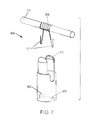
- FIG. 2 is a diagram of the structure of a cartomizer in an electronic cigarette.
- FIG. 3 is a diagram of the parts of a cartomizer in an electronic cigarette.
- FIG. 4 is diagram of a cartomizer structure with automation compatible parts.
- FIG. 5 is diagram of automation compatible parts in a cartomizer.
- FIG. 6 is a diagram of a container for the heater coil and wick.
- FIG. 7 is a diagram of the assembly of a container for the heater coil and wick.
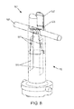
- FIG. 8 is a diagram of the heater coil assembly.
- FIG. 9 is a diagram of the conductive element assembly process.
- FIG. 10 is a diagram of the assembly process for the posts.
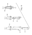
- FIG. 11 is a diagram of the assembly process for the posts using multiple conductors.
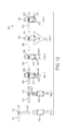
- FIG. 12 is a diagram of the assembly process for the container, heater coil, and wick.
- FIG. 13A is a diagram of the spacing of the container and FIG. 13B is an exploded diagram of the spacing of the container.
- FIG. 14 is a diagram of chamfers of the inner post.
- FIG. 15 is a diagram of an alternative view of chamfers in the inner post.
- FIG. 16 is a diagram of the inner and the outer posts with matching cone shaped portions.
- FIG. 17 is a diagram of an isolated tube with an inner post.
- a system and method may improve the structure of and assembly process for a cartomizer of an e-Cig.
- the improved cartomizer isolates certain components with features that can cause manufacturing difficulties and confines them as a sub-assembly (e.g. a wick and a heater coil into a wick-coil assembly) in a confining process.
- the sub-assembly's characteristics may be determined according to the requirements derived from its purpose and the environmental conditions, from the automated assembly process requirements and from requirements of miscellaneous bodies such as ISO, FDA and the like.
- the flexible parts, the self-disintegrating parts and the uneven parts may be tightly coupled to one another and/or to some other solid component, while being anchored around the extremities.
- an automated assembly process may be possible.
- the “confinement” may be either made consecutively or separately from the production and/or assembly stage. Implementing these confinement modifications and the changes to the structure of various components may improve the assembly process of the cartomizer.
- the assembly process allows for easy substitution and the flexibility of using different components as long as the different components are confined with similar characteristics and connectivity.
- terms, such as “a,” “an,” or “the,” again, may be understood to convey a singular usage or to convey a plural usage, depending at least in part upon context.
- the term “based on” may be understood as not necessarily intended to convey an exclusive set of factors and may, instead, allow for existence of additional factors not necessarily expressly described, again, depending at least in part on context.
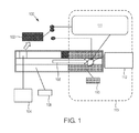
- FIG. 1 is a diagram of an electronic cigarette 100 .
- the “smoke” produced by the electronic cigarette 100 is a created by turning a liquid (e-Liquid 110 ) into mist and some vapor with an aerosol generating component 112 .
- the cartomizer 113 may include the aerosol generating component 112 and the e-Liquid 110 wherein the e-Liquid 110 is disposed in a storage space which can include a sponge which holds the e-Liquid 110 .
- the cartomizer 113 may also be referred to as a cartridge throughout this disclosure and may be disposable.
- the e-Liquid 110 may have a high viscosity at room temperature to enable longer shelf life and reduce leakages; however, this high viscosity may reduce the vaporization rate.
- the e-Liquid 110 is vaporized via air flow 108 in an air space, generated by the inhalation of the user (i.e. the smoker or consumer or vapor), which produces a pressure difference that removes e-Liquid droplets from the e-Liquid 110 .
- external heat may be applied through a heating element 111 .
- the e-Liquid 110 may be soaked in a wick (not shown) which draws the e-Liquid from the storage space toward the heating element 111 .
- the heating element 111 may be a heater coil that wraps around the wick in order to heat the e-Liquid on the wick.
- local viscosity reduction via heating, while inhalation occurs enables e-Liquid vaporization in the inhalation-generated flow of air 108 .
- the e-Liquid 110 may be heated via an electric current flowing through the heating element 111 and may then be vaporized and evaporated through the e-Cig and may contain tastes and aromas that create a smoking sensation.
- a controller 102 may be activated due to air flow 108 (from the inhaled air) passing a flow sensor 104 .
- the sensor 104 may be activated by the pressure drop across the sensor and may directly switch a battery 106 power on, or be used as an input for the controller 102 that then switches the battery 106 current on.
- the controller 102 may be a part of the e-Cig (e.g. along with the battery 106 ).
- the battery 106 may be a separate/removable assembly.
- the battery 106 may include one or more electronic chips controlling and communicating therewith.
- the battery 106 may connect with the cartomizer 113 , which can be replaced or changed (e.g. when a new/different e-Liquid 110 is desired).
- the e-Cig may include two parts.
- the first part is often just referred to as the battery or battery portion (i.e. battery enclosure) and it includes the battery 106 , the air flow sensor 104 and the controller 102 .
- the second part is the cartomizer 113 (i.e. cartridge) that is filled up with e-Liquid 110 and flavors that are required for smoke and flavor generation.
- the battery portion and the cartomizer may be connected by metal connectors.
- An airflow tube of the battery enclosure and an airflow tube of the cartomizer may enable the smoker to puff through the electronic cigarette and activate the airflow sensor 104 inside the battery portion. This may trigger the controller 102 and thereby cause the heating element (i.e.
- the e-Cig may include connections (i.e. connectors or electrical connections) that are used for power delivery from the battery 106 to the heating element 111 and for charging the battery 106 .
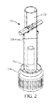
- FIG. 2 is a diagram of the structure of a manually assembled cartomizer 113 of an electronic cigarette.
- FIG. 2 illustrates metal parts including a post 312 and thread 316 , exposed conductive wires 308 which are arranged to be in the e-Liquid storage space of the electronic cigarette, and a flexible fiberglass sleeve 202 of the cartomizer 113 .
- the cartomizer 113 as illustrated in FIG. 2 may be manually assembled.
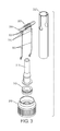
- FIG. 3 is a diagram of parts of a cartomizer 113 of an electronic cigarette.
- FIG. 3 illustrates parts (i.e. components) from the cartomizer 113 as shown in FIG. 2 .
- a heater coil 305 is wound around the wick 306 .
- leads 307 of the heater coil 305 are connected to the conducting wires 308 by external crimps 310 , and each of the other ends of the conducting wires 308 can be connected by various methods to the metal parts such as the post 312 and the thread 316 .
- the term “metal parts” refers to at least a first and a second conductive bodies which are arranged to electrically connect respective poles of the battery of the electronic cigarette with one of the respective conducting wires 308 such that the battery is in electrical contact with the heater coil 305 and wherein the metal parts form part of the structure of the cartomizer 113 as well as an e-Liquid seal which confines e-Liquid 110 in the storage space of the cartomizer 113 .
- connecting the conducting wires 308 to the post 312 and/or the thread 316 is based on inserting the tips of the conducting wires 308 (the ends of each the conducting wires which are not connected to the heater coil 305 ) to a respective one of the metal parts such as the post 312 and the thread 316 wherein an insulating ring 315 electrically isolates the post 312 from the thread 316 such that an electrical circuit can be formed between the cartomizer 113 and the battery portion.
- the connection of the conducting wires 308 to the leads 307 of the heater coil 305 may be forgone wherein the leads 307 of the heater coil 305 are connected to the metal parts (i.e.
- the seals of the cartomizer 113 should not be compromised, and further there is a possibility of heat buildup in the heater coil 305 starting at contact points wherein one of the leads 307 contacts the post 312 or the thread 316 .
- the heater coil 305 may need to be in close proximity to the contact points, instead of the mid-section of the cartomizer 113 so as to enable optimal utilization of the e-Liquid 110 .
- connection of the heater coil 305 to the contacts points and the location processes which position the heater 305 in the fiberglass tube 202 may involve the insertion of the wick 306 and heater coil 305 into the fiberglass tube 202 , or conversely placing the fiberglass tube 202 around a wick-coil assembly 306 / 305 formed from the wick 306 and heater coil 305 .
- wick-coil assembly 306 / 305 formed from the wick 306 and heater coil 305 .
- distortions and misplacements between the heater coil 305 and wick 306 or between the wick-coil assembly 306 / 305 and the fiberglass tube 202 can occur.
- the elasticity requirements for assembly purposes of the cartomizer 113 thus meant that the conducting wires 308 were located within the storage space occupied by the e-Liquid 110 and optionally the sponge, rather than the airflow space 108 (see FIG. 1 ), with all the consequences of the e-Liquid's effect on the conductors 308 and vice-versa, as far as materials composition and component temperature are concerned.
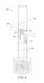
- FIG. 4 is diagram of a cartomizer assembly 500 which has parts that are automation compatible.
- FIG. 5 illustrates the parts of the cartomizer assembly 500 as shown in FIG. 4 wherein the parts are automation compatible.
- electrical conductors 501 (as used herein conductors) built as conductive strips and/or wires connected on one side to the battery leads (not shown).
- the other sides of the conductors 501 are supported by a container 502 that contains a wick 506 and a heater coil 505 to form a container assembly 600 .
- the container 502 can support the conductors 501 when the container 502 is put (e.g.
- Contact pressure between the heater coil leads 507 and the conductors 501 can be created by the container 502 such that sufficient contact between any diameters of wire of the heater coil leads 507 to any size of the conductor 501 and between all types of materials thereof can be achieved.
- This structure with changes between sealing and electrical conduction, thereby enables changes to the metallic raw material in some of the components of the cartomizer assembly 500 that may be replaced with plastic raw material.
- the assembly method is based on the knowledge of the location and orientation of the wick 506 and the heater coil 505 forming a wick-coil assembly 506 / 505 (as used herein a “set”) when exiting a winding machine that forms the sets. After a set exits the winding machine and after the sets disconnection from the other sets formed by the winding machine, a process is executed by which a mechanical clamp grabs the set and feeds it into the container 502 . In machines in which the wick cutting occurs before winding the heater coil therearound, the stage of grabbing the product as a set may occur after the winding and the cutting of the wire are completed.
- the cartomizer assembly 500 can also include a sleeve 512 , such as a fiber glass sleeve, disposed above the container 502 .
- the cartomizer assembly 500 can also include an inner post 504 , thread 516 , and an outer post 508 disposed below the container 502 .
- FIG. 6 is a diagram of a container 502 for the heater coil 505 and wick 506 which forms a container assembly 600 .
- FIG. 6 illustrates the way the wick 506 and the heater coil 505 are located in the container 502 , and the heater coil tips (i.e. heater coil leads 507 ) that are held in the location notches 503 of the container 502 , in a way that allows the automatic assembly process to be performed.
- the entire heater coil 505 is confined inside the container 502 wherein the heater coil 505 surrounds the wick 506 such that there is no possibility of the heater coil 505 coming into contact with a sponge that is located outside the container 502 . Later in the process the heater coil tips (i.e.
- heater coil leads 507 are placed into designated grooves (i.e. the location notches 503 ) in container 502 and bent outwards, both for positioning purposes as specified and to prevent the wire of the heater coil from changing position during assembly thereof such that the heater coil 505 and wick 506 remain in place in the container 502 .
- the position of the conductors 501 may be isolated either from the airflow space or the e-Liquid soaked in the sponge in the storage space as previous constraints dictated, and therefore, by isolating the conductors 501 harmful and unwanted mutual effects caused by positioning the conductors 501 in the airflow space or the storage space can be prevented.
- FIG. 7 is a diagram of the container assembly 600 formed of a container 502 , the heater coil 505 and wick 506 wherein the container contains the heater coil 505 and wick 506 .
- FIG. 7 illustrates the container 502 before an assembly process for the cartomizer assembly shown in FIG. 6 has been performed and further illustrates the location of the heater coil 505 in the container 502 .
- the container 502 may be designed according to requirements that stem from its role and its use as well as according to requirements and guidelines originating from standardization and regulatory organizations (e.g. the Food and Drug Administration).
- the container 502 may be resistant to temperatures as high as those that occur in the close environment of the heater coil 505 and to their regimens, and it will have the mechanical robustness required to apply the contact pressure needed to electrically connect the heater coil leads 507 with the conductors (not shown), and will feature sufficient heat conductivity combined with low thermal mass so as to enable appropriate heat dissipation from the heater coil 505 to the areas where the wick 506 enters the airflow space to enable heating the e-Liquid soaked sponge and reduce the viscosity of the E-liquid in order to improve flow in the wick 506 .
- the temperature in the heater coil 505 may be up to 600° C. while in the area of the container 502 ; about 250° C. may be expected.
- the temperatures may be lower.
- the container 502 may be anodized aluminum or another metal that is suited to surface treatment with similar characteristics.
- the surface treatment may be incomplete or partial but the electrical isolation must be kept in places where at least one heater coil lead 507 and a respective conductor 501 are touching to prevent a shortcut for the electrical current supplied therethrough.
- the shape of the container 502 may enable the set that is inserted or released into it to settle in an optimal fashion at the center of the container without warping and also to place the heater coil leads 507 in a place and orientation that will lead to optimal tightening to the conductors 501 .
- the container 502 is tubular shaped.
- the design of the conductors 501 by structure and material is used not only for conducting the electrical current into the heater coil 505 , but also for conducting and thereby removing the excess heat that develops in the heater coil 505 , (excess because of the position of the conductors at the edges of the heater coil leads 507 that heat up only after heating the center of the heater coil 505 ) toward the larger metal parts of the battery leads outside the cartomizer assembly.
- Some of the heat that develops in the heater coil 505 is conducted by the container 502 toward the sponge and e-Liquid surrounding it which can cause a decrease in e-Liquid viscosity and improve the e-Liquid flow within the wick, and thus improve the smoking experience.
- FIG. 8 is a diagram of the container assembly 600 included on a post assembly 700 of the cartomizer assembly.
- FIG. 8 illustrates the way the heater coil leads 507 are pressed against the conductors 501 .
- This structure may eliminate a need for crimping or soldering the heater coil leads 507 to the respective conductors 501 .
- the design change and the container 502 enable the connection of a rigid tube in the airway, which improves the quality of the sealed airway between the e-Liquid and also allows the use of a material with a good thermal conductivity within the hot air route which contains generated mist. This results in thermal energy dissipation toward the contact area between the e-Liquid/sponge and the tube. This contributes to the cooling of the tube together with the reduction in e-Liquid viscosity at the contact area that will lead to improved e-Liquid flow to the wick area.
- the method for the insertion of a conductor 501 allows the use of more efficient, commercially available materials and production methods, and opens up possibilities for automating the assembly process as well as upgrading it into a “green” process in terms of material and energy resources necessary for assembly.
- Simplification and flexibility in the assembly process tabs have been added to several parts as shown in FIGS. 7-8 whose function is to allow the placement of parts in the required orientation by simple means of slants on the sides that lead to the product to the necessary position and orientation.
- FIG. 9 is a diagram of an assembly process of forming conductors 501 which are disposed in the inner and outer posts 504 , 508 .
- FIG. 9 illustrates the steps in which the conductors 501 are formed.
- a conductive strip 550 such as a metal strip, is fed as a straight strip between an inner post 504 and an outer post 508 .
- the inner post 504 is inserted into the outer post 508 which locks the conductive strip 550 in place.
- the inner post 504 and the outer post 508 can be cylindrical wherein the inner post 504 fits in the outer post 508 .
- a punch 900 is inserted through a hole 551 in the inner post 504 after the conductive strip 550 is locked in place such that the conductive strip 550 is cut in the middle into two separate conductors 501 .
- the conductive strip 550 may be soft so that the punch 900 can be inserted easily to form the conductors 501 .
- the conductive strip 550 used to form the conductors 501 is added therebetween, so that the act of inserting the inner post 504 into the outer post 508 positions the conductive strip 550 or conductors 501 in place while obtaining a seal that fixes the conductors 501 in place.
- the conductive strip 550 can be fed as a connected strip wherein the separation thereof into two sections to form the conductors 501 is performed after the completion of insertion process.
- the conductors 501 can be fed in the insertion process as two separate units.
- the utilization of conductors 501 with large surface area and volume enables the heat conduction from the heater coil 505 to the outside.
- the inner post's 504 resilience to heat that develops at the heater coil 505 can be improved by creating gradients and moving margins that are not essential for proper functioning of the electronic cigarette away from the heat. Further improvement may be achieved by masking the part by the electrical conductors 501 that block and conduct the heat in order to disperse it away towards the relatively high thermal mass thereof in comparison with the heater coil 505 . Since e-Cig smoking is not continuous, the temperature within the conductors 501 and other parts of the e-Cig does not significantly rise.
- FIG. 10 is a diagram of the assembly process for the inner and outer posts 504 , 508 .
- FIG. 10 illustrates exemplary steps to assemble the inner post 504 into the outer post 508 with a harder metal conductive strip 550 than was shown in FIG. 9 .
- the hardness of the inner post 504 or outer post 508 is decreased below that of the metal conductive strip 550 , there may be bending of the metal conductive strip 550 before insertion between the inner and outer posts 504 , 508 .
- the operation as illustrated in step four may be similar to that illustrated in FIG. 9 in order to cut the metal conductive strip 550 into two separate conductors 501 .
- FIG. 11 is a diagram of the assembly process for the inner and outer posts 504 , 508 wherein conductors 501 are utilized in the assembly process.
- FIG. 11 illustrates the assembly operation with two separate conductors 501 instead of a single conductive strip.
- the feeding stage of the conductors 501 may be more difficult, the cutting step becomes unnecessary.
- FIG. 12 is a diagram of the assembly process for a container assembly 600 including container 502 , wick 506 and heater 505 .
- FIG. 12 illustrates exemplary steps for assembly of the container 502 shown in FIG. 7 .
- the wick 506 and heater coil 505 can be dropped into the container 502 such that they are located and directed to position based on the shapes of the heater coil 505 , wick 506 , and container 502 (see step 1 ).
- the heater coil leads are inserted into the container 502 when the wick 506 and heater coil 505 are dropped into the container 502 (see step 2 ).
- step 3 the wick 506 and the heater coil 505 are in the container 502 at the desired location, but the heater coil leads 507 may be at an incorrect location.
- step four the heater coil leads 507 are moved to the proper location based on the location notches 503 .
- step five the wick 506 and heater coil 505 are anchored by the heater coil leads 507 in order to assure quality contact.
- step six the heater coil leads 507 are bent in order to improve the location, and prevent movements during the next assembly step of pressing the container 502 on the conductors 501 and the inner post 504 as shown in FIG. 8 .
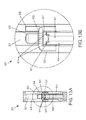
- FIG. 13A is a diagram of the spacing of the container 502 in the cartomizer assembly 500 and FIG. 13B is an exploded view of the spacing of the container 502 in the cartomizer assembly 500 .
- FIGS. 13A and 13B illustrate the advantages of the cartomizer assembly 500 by isolating the conductors 501 from an e-Liquid container (i.e. liquid storage space) 520 while also minimizing exposure to the air flow in an air space 521 , and shielding the front area of the inner post 504 from exposure to heat generated by the heater coil 505 .
- the electric current flow from leads of the battery takes place directly through the conductors 501 which form failure-prone connections with the heater coil leads 507 and therefore eliminates the need to produce the carrier and sealing parts from expensive and superfluous metal, but rather from plastic materials.
- the location of the conductors 501 is not in the e-Liquid in the e-Liquid container 520 and therefore they are not subject to the mutual effect on/from the e-Liquid.
- the location may not be entirely in the air space 521 either so that its mutual effect on/from the aerosol mist is minimal.
- the design of the conductors 501 with a ring on one pole and/or two rings to both poles of the battery allows using batteries in which the surface of the poles are not uniform and smooth, but rather, notched for various reasons such as to accommodate side vents.
- the elastic properties of the conductors 501 may be improved by changing their shape and/or adding a tab whose physical structure allows it to be springy and/or creating a double wall, triple wall or more in order to obtain condensation at the necessary places and applications.
- FIG. 14 is a diagram of the chamfers 513 of the inner post 504 at the front of the inner post 504 that is configured to be located near the heater coil (not shown).
- FIG. 15 is a diagram of an alternative view of the chamfers 513 of the inner post 504 .
- the front side exposure of the chamfers 513 to heat from the heater coil is lowered in this design.
- “orientation fingers” 515 of the inner post 504 may streamline the assembly process by creating a simple way to locate the inner post 504 in the desired place and orientation such as in the outer post 508 .
- the chamfers 513 may be a notch in the inner post 504 .
- the chamfers 513 on the side close to the heater coil are made to increase the distance from the heater coil and reduce the surface temperature. Because of its location near the heater coil, the inner post 504 may be used to contain any object that can improve the cartomizer assembly's operation, such as a temperature tester, or any other electronic equipment.
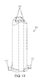
- FIG. 16 is a diagram of the inner post 504 which is cone shaped (conical).
- the outer post 508 may have a matching cone therein for locking with the cone shaped inner post 504 . The locking may thus occur with less power or pressure.
- the cone shapes of the inner and outer posts 504 , 508 can be along the entire length or part of the length of the inner and outer posts 504 , 508 while the rest of the inner and outer posts 504 , 508 are parallel.
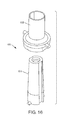
- FIG. 17 is a diagram of an isolated tube 580 included with an inner post 504 .
- FIG. 17 shows an optional isolated tube 580 disposed under the conductive strip 550 , which is used to form the conductors 501 , for support above the inner post 504 .
- the optional isolated tube 580 may be located between the conductive strip 550 and the inner post 504 upper surface, while electrical contact is still maintained between the conductors 501 and the heater coil leads (not shown) after the conductors 501 have been formed from the conductive strip 550 .
Landscapes
- Catching Or Destruction (AREA)
- Handcart (AREA)
- Resistance Heating (AREA)
- Disinfection, Sterilisation Or Deodorisation Of Air (AREA)
- Filling Or Discharging Of Gas Storage Vessels (AREA)
Abstract
Description
- This application is a divisional of U.S. application Ser. No. 14/335,436, filed on Jul. 18, 2014, which claims priority under 35 U.S.C. §119(e) to U.S. Provisional Application No. 61/857,956, filed on Jul. 24, 2013, the entire content of each of which are incorporated herein by reference thereto.
- An electronic cigarette (“e-cigarette” or “e-Cig”) is a device that emulates tobacco cigarette smoking by producing smoke replacement that may be similar to tobacco cigarette smoke in its physical sensation, general appearance, and sometimes flavor (i.e., with tobacco fragrance, menthol taste, added nicotine etc.). A battery portion of the e-Cig includes a controller and battery for powering the device and a cartomizer portion (i.e. cartomizer assembly) which generates an aerosol mist (i.e. vapor) that is a replacement for cigarette smoke. The cartomizer may use heat, ultrasonic energy, or other means to atomize/vaporize a liquid solution (for example based on propylene glycol, or glycerin, for example including taste and fragrance ingredients) into an aerosol mist. The liquid solution may be similar to nebulizer or humidifier vaporizing solutions for inhalation. The component in the cartomizer that generates the mist (as used herein aerosol generating component) is sometimes referred to as the cartomizer itself. The cartomizer typically includes a space (as used herein “liquid storage space”) that contains the required fluid or liquid (e.g. e-Liquid) used for generating the mist and another space (as used herein “airflow space”) for airflow. The e-Liquid can be absorbed or held in a sponge which is disposed in the storage space. Transferring the e-Liquid from its storage space to the airflow space wherein the e-Liquid is subsequently heated can cause the density of the e-Liquid to decrease, and these factors together with the air flow triggered by the inhalation of a user provide challenges in automation of the cartomizer assembly.
- In order to create the storage space, the airflow space, and a separation therebetween, the cartomizer can include flexible parts, self-disintegrating parts, and uneven parts. These characteristics may become accentuated at the components' extremities such as the extremities of a wick, or a coil, etc., which may hinder and even altogether preclude the possibility for an automated assembly process of forming the cartomizer. Even in the presence of machines that produce subassemblies of several components together, the general assembly process of the cartomizer may be based on human intervention that can deal with the various characteristics of the components thereof.
- Disclosed herein is a cartomizer assembly of an electronic cigarette which is configured to connect with a battery portion of the electronic cigarette wherein the cartomizer assembly is formed from automated assembly compatible parts. The cartomizer assembly comprises a container assembly including a container and a heater coil surrounding a wick in an airflow space of the container wherein the entire coil of the heater coil is inside the container. The heater coil is configured to heat liquid on the wick to generate an aerosol mist during a vaporization process. A liquid storage space is in liquid communication with the wick and is operable to supply liquid to the wick. The heater, the wick, and the container are shaped such that the heater and wick can be dropped into the container during automated assembly thereof and be directed to and located at a desired location in the container.
- Also disclosed herein is a method of assembling a container assembly of a cartomizer assembly of an electronic cigarette wherein the container assembly is formed from automated assembly compatible parts. The method comprises winding a heater coil around a wick, dropping the heater coil and wick into a container, and locating heater coil leads of the heater coil in location notches of the container. The heater, the wick, and the container are each shaped such that the heater and wick can be dropped into the container during automated assembly thereof and be directed to and located at a desired location in the container.
- Further disclosed herein is a method of assembling a cartomizer assembly of an electronic cigarette wherein the cartomizer assembly is formed from automated assembly compatible parts. The method comprises inserting an inner post into an outer post wherein a conductive strip is disposed therebetween, and inserting a punch into a hole in the inner post wherein the punch removes a portion of the conductive strip so as to form conductors.
- Non-limiting and non-exhaustive embodiments are described with reference to the following drawings. The components in the drawings are not necessarily to scale, emphasis instead being placed upon illustrating the principles of embodiments as disclosed herein. In the drawings, like referenced numerals designate corresponding parts throughout the different views.
-
FIG. 1 is a diagram of an electronic cigarette. -
FIG. 2 is a diagram of the structure of a cartomizer in an electronic cigarette. -
FIG. 3 is a diagram of the parts of a cartomizer in an electronic cigarette. -
FIG. 4 is diagram of a cartomizer structure with automation compatible parts. -
FIG. 5 is diagram of automation compatible parts in a cartomizer. -
FIG. 6 is a diagram of a container for the heater coil and wick. -
FIG. 7 is a diagram of the assembly of a container for the heater coil and wick. -
FIG. 8 is a diagram of the heater coil assembly. -
FIG. 9 is a diagram of the conductive element assembly process. -
FIG. 10 is a diagram of the assembly process for the posts. -
FIG. 11 is a diagram of the assembly process for the posts using multiple conductors. -
FIG. 12 is a diagram of the assembly process for the container, heater coil, and wick. -
FIG. 13A is a diagram of the spacing of the container andFIG. 13B is an exploded diagram of the spacing of the container. -
FIG. 14 is a diagram of chamfers of the inner post. -
FIG. 15 is a diagram of an alternative view of chamfers in the inner post. -
FIG. 16 is a diagram of the inner and the outer posts with matching cone shaped portions. -
FIG. 17 is a diagram of an isolated tube with an inner post. - By way of introduction, a system and method may improve the structure of and assembly process for a cartomizer of an e-Cig. The improved cartomizer isolates certain components with features that can cause manufacturing difficulties and confines them as a sub-assembly (e.g. a wick and a heater coil into a wick-coil assembly) in a confining process. The sub-assembly's characteristics may be determined according to the requirements derived from its purpose and the environmental conditions, from the automated assembly process requirements and from requirements of miscellaneous bodies such as ISO, FDA and the like. In the confining process, the flexible parts, the self-disintegrating parts and the uneven parts may be tightly coupled to one another and/or to some other solid component, while being anchored around the extremities. As a result of this confining process, an automated assembly process may be possible. The “confinement” may be either made consecutively or separately from the production and/or assembly stage. Implementing these confinement modifications and the changes to the structure of various components may improve the assembly process of the cartomizer. The assembly process allows for easy substitution and the flexibility of using different components as long as the different components are confined with similar characteristics and connectivity.
- Other systems, methods, features and advantages will be, or will become, apparent to one with skill in the art upon examination of the following figures and detailed description. It is intended that all such additional systems, methods, features and advantages be included within this description, be within the scope of embodiments as disclosed herein, and be protected by the following claims. Nothing in this section should be taken as a limitation on those claims. Further aspects and advantages are discussed below.
- Subject matter will now be described more fully hereinafter with reference to the accompanying drawings, which form a part hereof, and which show, by way of illustration, specific example embodiments. Subject matter may, however, be embodied in a variety of different forms, and therefore, covered or claimed subject matter is intended to be construed as not being limited to any example embodiments set forth herein; example embodiments are provided merely to be illustrative Likewise, a reasonably broad scope for claimed or covered subject matter is intended. Among other things, for example, subject matter may be embodied as methods, devices, components, or systems. Accordingly, embodiments may, for example, take the form of hardware, software, firmware or any combination thereof (other than software per se). The following detailed description is, therefore, not intended to be taken in a limiting sense.
- Throughout the specification and claims, terms may have nuanced meanings suggested or implied in context beyond an explicitly stated meaning. Likewise, the phrase “in one embodiment” as used herein does not necessarily refer to the same embodiment and the phrase “in another embodiment” as used herein does not necessarily refer to a different embodiment. It is intended, for example, that claimed subject matter include combinations of example embodiments in whole or in part.
- In general, terminology may be understood at least in part from usage in context. For example, terms, such as “and”, “or”, or “and/or,” as used herein may include a variety of meanings that may depend at least in part upon the context in which such terms are used. Typically, “or” if used to associate a list, such as A, B or C, is intended to mean A, B, and C, here used in the inclusive sense, as well as A, B or C, here used in the exclusive sense. In addition, the term “one or more” as used herein, depending at least in part upon context, may be used to describe any feature, structure, or characteristic in a singular sense or may be used to describe combinations of features, structures or characteristics in a plural sense. Similarly, terms, such as “a,” “an,” or “the,” again, may be understood to convey a singular usage or to convey a plural usage, depending at least in part upon context. In addition, the term “based on” may be understood as not necessarily intended to convey an exclusive set of factors and may, instead, allow for existence of additional factors not necessarily expressly described, again, depending at least in part on context.
-
FIG. 1 is a diagram of anelectronic cigarette 100. The “smoke” produced by theelectronic cigarette 100 is a created by turning a liquid (e-Liquid 110) into mist and some vapor with anaerosol generating component 112. Thecartomizer 113 may include theaerosol generating component 112 and the e-Liquid 110 wherein thee-Liquid 110 is disposed in a storage space which can include a sponge which holds thee-Liquid 110. Thecartomizer 113 may also be referred to as a cartridge throughout this disclosure and may be disposable. The e-Liquid 110 may have a high viscosity at room temperature to enable longer shelf life and reduce leakages; however, this high viscosity may reduce the vaporization rate. Thee-Liquid 110 is vaporized viaair flow 108 in an air space, generated by the inhalation of the user (i.e. the smoker or consumer or vapor), which produces a pressure difference that removes e-Liquid droplets from thee-Liquid 110. In order to reduce the e-Liquid viscosity, to a level enabling vaporization of the e-Liquid, external heat may be applied through aheating element 111. In one embodiment, the e-Liquid 110 may be soaked in a wick (not shown) which draws the e-Liquid from the storage space toward theheating element 111. In an embodiment, theheating element 111 may be a heater coil that wraps around the wick in order to heat the e-Liquid on the wick. In this embodiment, local viscosity reduction via heating, while inhalation occurs, enables e-Liquid vaporization in the inhalation-generated flow ofair 108. The e-Liquid 110 may be heated via an electric current flowing through theheating element 111 and may then be vaporized and evaporated through the e-Cig and may contain tastes and aromas that create a smoking sensation. Acontroller 102 may be activated due to air flow 108 (from the inhaled air) passing aflow sensor 104. Thesensor 104 may be activated by the pressure drop across the sensor and may directly switch abattery 106 power on, or be used as an input for thecontroller 102 that then switches thebattery 106 current on. Although illustrated as separate from the e-Cig, thecontroller 102 may be a part of the e-Cig (e.g. along with the battery 106). Thebattery 106 may be a separate/removable assembly. Thebattery 106 may include one or more electronic chips controlling and communicating therewith. Thebattery 106 may connect with thecartomizer 113, which can be replaced or changed (e.g. when a new/different e-Liquid 110 is desired). - The e-Cig may include two parts. The first part is often just referred to as the battery or battery portion (i.e. battery enclosure) and it includes the
battery 106, theair flow sensor 104 and thecontroller 102. The second part is the cartomizer 113 (i.e. cartridge) that is filled up withe-Liquid 110 and flavors that are required for smoke and flavor generation. The battery portion and the cartomizer may be connected by metal connectors. An airflow tube of the battery enclosure and an airflow tube of the cartomizer may enable the smoker to puff through the electronic cigarette and activate theairflow sensor 104 inside the battery portion. This may trigger thecontroller 102 and thereby cause the heating element (i.e. a heater coil) 111 inside the cartomizer to get hot, evaporate the e-Liquid that is in the cartomizer and form vapor. Although not shown inFIG. 1 , the e-Cig may include connections (i.e. connectors or electrical connections) that are used for power delivery from thebattery 106 to theheating element 111 and for charging thebattery 106. -
FIG. 2 is a diagram of the structure of a manually assembledcartomizer 113 of an electronic cigarette.FIG. 2 illustrates metal parts including apost 312 andthread 316, exposedconductive wires 308 which are arranged to be in the e-Liquid storage space of the electronic cigarette, and aflexible fiberglass sleeve 202 of thecartomizer 113. Thecartomizer 113 as illustrated inFIG. 2 may be manually assembled. -
FIG. 3 is a diagram of parts of acartomizer 113 of an electronic cigarette.FIG. 3 illustrates parts (i.e. components) from thecartomizer 113 as shown inFIG. 2 . In the manually assembledcartomizer 113, aheater coil 305 is wound around thewick 306. Later in the assembly process, leads 307 of theheater coil 305 are connected to the conductingwires 308 byexternal crimps 310, and each of the other ends of the conductingwires 308 can be connected by various methods to the metal parts such as thepost 312 and thethread 316. As used herein, the term “metal parts” refers to at least a first and a second conductive bodies which are arranged to electrically connect respective poles of the battery of the electronic cigarette with one of therespective conducting wires 308 such that the battery is in electrical contact with theheater coil 305 and wherein the metal parts form part of the structure of thecartomizer 113 as well as an e-Liquid seal which confines e-Liquid 110 in the storage space of thecartomizer 113. - In some products, connecting the conducting
wires 308 to thepost 312 and/or thethread 316 is based on inserting the tips of the conducting wires 308 (the ends of each the conducting wires which are not connected to the heater coil 305) to a respective one of the metal parts such as thepost 312 and thethread 316 wherein an insulatingring 315 electrically isolates thepost 312 from thethread 316 such that an electrical circuit can be formed between thecartomizer 113 and the battery portion. In an embodiment, the connection of the conductingwires 308 to theleads 307 of theheater coil 305 may be forgone wherein theleads 307 of theheater coil 305 are connected to the metal parts (i.e. therespective post 312 and thread 316) at contact points thereof (as used herein contact points). In this embodiment, the seals of thecartomizer 113 should not be compromised, and further there is a possibility of heat buildup in theheater coil 305 starting at contact points wherein one of theleads 307 contacts thepost 312 or thethread 316. In an embodiment, theheater coil 305 may need to be in close proximity to the contact points, instead of the mid-section of thecartomizer 113 so as to enable optimal utilization of thee-Liquid 110. - The connection of the
heater coil 305 to the contacts points and the location processes which position theheater 305 in thefiberglass tube 202 may involve the insertion of thewick 306 andheater coil 305 into thefiberglass tube 202, or conversely placing thefiberglass tube 202 around a wick-coil assembly 306/305 formed from thewick 306 andheater coil 305. During the placement of the wick-coil assembly 306/305 in thefiberglass tube 202 distortions and misplacements between theheater coil 305 andwick 306 or between the wick-coil assembly 306/305 and thefiberglass tube 202 can occur. Further, if part of theheater coil 305 were to touch the sponge (not shown), which holds the e-Liquid 110, it may cause burning of the sponge during heating of theheater coil 305. As such, the elasticity requirements for assembly purposes of thecartomizer 113 thus meant that the conductingwires 308 were located within the storage space occupied by the e-Liquid 110 and optionally the sponge, rather than the airflow space 108 (seeFIG. 1 ), with all the consequences of the e-Liquid's effect on theconductors 308 and vice-versa, as far as materials composition and component temperature are concerned. -
FIG. 4 is diagram of acartomizer assembly 500 which has parts that are automation compatible.FIG. 5 illustrates the parts of thecartomizer assembly 500 as shown inFIG. 4 wherein the parts are automation compatible. As illustrated inFIGS. 4 and 5 , there are electrical conductors 501 (as used herein conductors) built as conductive strips and/or wires connected on one side to the battery leads (not shown). The other sides of theconductors 501 are supported by acontainer 502 that contains awick 506 and aheater coil 505 to form acontainer assembly 600. Preferably, thecontainer 502 can support theconductors 501 when thecontainer 502 is put (e.g. snapped) into place in thecartomizer assembly 500, such as by putting the container on aninner post 504 of the of thecartomizer assembly 500. By snapping thecontainer 502 into place the required mechanical fixation of theconductors 501 is created wherein the mechanical fixation of theconductors 501 also results in contact between the heater coil leads 507 and theconductors 501. This eliminates the need for crimp connections, laser welding or any other external welding method, and therefore simplifies manufacturing processes of thecartomizer assembly 500. Contact pressure between the heater coil leads 507 and theconductors 501 can be created by thecontainer 502 such that sufficient contact between any diameters of wire of the heater coil leads 507 to any size of theconductor 501 and between all types of materials thereof can be achieved. This structure, with changes between sealing and electrical conduction, thereby enables changes to the metallic raw material in some of the components of thecartomizer assembly 500 that may be replaced with plastic raw material. - The assembly method is based on the knowledge of the location and orientation of the
wick 506 and theheater coil 505 forming a wick-coil assembly 506/505 (as used herein a “set”) when exiting a winding machine that forms the sets. After a set exits the winding machine and after the sets disconnection from the other sets formed by the winding machine, a process is executed by which a mechanical clamp grabs the set and feeds it into thecontainer 502. In machines in which the wick cutting occurs before winding the heater coil therearound, the stage of grabbing the product as a set may occur after the winding and the cutting of the wire are completed. - As shown in
FIG. 5 , thecartomizer assembly 500 can also include asleeve 512, such as a fiber glass sleeve, disposed above thecontainer 502. Thecartomizer assembly 500 can also include aninner post 504,thread 516, and anouter post 508 disposed below thecontainer 502. -
FIG. 6 is a diagram of acontainer 502 for theheater coil 505 andwick 506 which forms acontainer assembly 600. In particular,FIG. 6 illustrates the way thewick 506 and theheater coil 505 are located in thecontainer 502, and the heater coil tips (i.e. heater coil leads 507) that are held in thelocation notches 503 of thecontainer 502, in a way that allows the automatic assembly process to be performed. In this structure theentire heater coil 505 is confined inside thecontainer 502 wherein theheater coil 505 surrounds thewick 506 such that there is no possibility of theheater coil 505 coming into contact with a sponge that is located outside thecontainer 502. Later in the process the heater coil tips (i.e. heater coil leads 507) are placed into designated grooves (i.e. the location notches 503) incontainer 502 and bent outwards, both for positioning purposes as specified and to prevent the wire of the heater coil from changing position during assembly thereof such that theheater coil 505 andwick 506 remain in place in thecontainer 502. In this embodiment, the position of theconductors 501 may be isolated either from the airflow space or the e-Liquid soaked in the sponge in the storage space as previous constraints dictated, and therefore, by isolating theconductors 501 harmful and unwanted mutual effects caused by positioning theconductors 501 in the airflow space or the storage space can be prevented. -
FIG. 7 is a diagram of thecontainer assembly 600 formed of acontainer 502, theheater coil 505 andwick 506 wherein the container contains theheater coil 505 andwick 506. In particular,FIG. 7 illustrates thecontainer 502 before an assembly process for the cartomizer assembly shown inFIG. 6 has been performed and further illustrates the location of theheater coil 505 in thecontainer 502. Thecontainer 502 may be designed according to requirements that stem from its role and its use as well as according to requirements and guidelines originating from standardization and regulatory organizations (e.g. the Food and Drug Administration). Thecontainer 502 may be resistant to temperatures as high as those that occur in the close environment of theheater coil 505 and to their regimens, and it will have the mechanical robustness required to apply the contact pressure needed to electrically connect the heater coil leads 507 with the conductors (not shown), and will feature sufficient heat conductivity combined with low thermal mass so as to enable appropriate heat dissipation from theheater coil 505 to the areas where thewick 506 enters the airflow space to enable heating the e-Liquid soaked sponge and reduce the viscosity of the E-liquid in order to improve flow in thewick 506. In one embodiment, the temperature in theheater coil 505 may be up to 600° C. while in the area of thecontainer 502; about 250° C. may be expected. If temperature control is applied, then the temperatures may be lower. There may be electrical isolation between thecontainer 502, the case of the electronic cigarette, the heater coil leads 507, and other components of the cartomizer assembly or electronic cigarette. In one embodiment, thecontainer 502 may be anodized aluminum or another metal that is suited to surface treatment with similar characteristics. In another embodiment the surface treatment may be incomplete or partial but the electrical isolation must be kept in places where at least oneheater coil lead 507 and arespective conductor 501 are touching to prevent a shortcut for the electrical current supplied therethrough. The shape of thecontainer 502 may enable the set that is inserted or released into it to settle in an optimal fashion at the center of the container without warping and also to place the heater coil leads 507 in a place and orientation that will lead to optimal tightening to theconductors 501. Preferably thecontainer 502 is tubular shaped. - The design of the
conductors 501 by structure and material is used not only for conducting the electrical current into theheater coil 505, but also for conducting and thereby removing the excess heat that develops in theheater coil 505, (excess because of the position of the conductors at the edges of the heater coil leads 507 that heat up only after heating the center of the heater coil 505) toward the larger metal parts of the battery leads outside the cartomizer assembly. Some of the heat that develops in theheater coil 505 is conducted by thecontainer 502 toward the sponge and e-Liquid surrounding it which can cause a decrease in e-Liquid viscosity and improve the e-Liquid flow within the wick, and thus improve the smoking experience. -
FIG. 8 is a diagram of thecontainer assembly 600 included on apost assembly 700 of the cartomizer assembly. In particular,FIG. 8 illustrates the way the heater coil leads 507 are pressed against theconductors 501. This structure may eliminate a need for crimping or soldering the heater coil leads 507 to therespective conductors 501. The design change and thecontainer 502 enable the connection of a rigid tube in the airway, which improves the quality of the sealed airway between the e-Liquid and also allows the use of a material with a good thermal conductivity within the hot air route which contains generated mist. This results in thermal energy dissipation toward the contact area between the e-Liquid/sponge and the tube. This contributes to the cooling of the tube together with the reduction in e-Liquid viscosity at the contact area that will lead to improved e-Liquid flow to the wick area. - The method for the insertion of a
conductor 501 allows the use of more efficient, commercially available materials and production methods, and opens up possibilities for automating the assembly process as well as upgrading it into a “green” process in terms of material and energy resources necessary for assembly. Simplification and flexibility in the assembly process tabs have been added to several parts as shown inFIGS. 7-8 whose function is to allow the placement of parts in the required orientation by simple means of slants on the sides that lead to the product to the necessary position and orientation. One may also use the tabs that are created at the point of entry of the material product notch in the injection molds for the same purpose. -
FIG. 9 is a diagram of an assembly process of formingconductors 501 which are disposed in the inner andouter posts FIG. 9 illustrates the steps in which theconductors 501 are formed. During the assembly process, aconductive strip 550, such as a metal strip, is fed as a straight strip between aninner post 504 and anouter post 508. Theinner post 504 is inserted into theouter post 508 which locks theconductive strip 550 in place. In an embodiment theinner post 504 and theouter post 508 can be cylindrical wherein theinner post 504 fits in theouter post 508. Apunch 900 is inserted through ahole 551 in theinner post 504 after theconductive strip 550 is locked in place such that theconductive strip 550 is cut in the middle into twoseparate conductors 501. Theconductive strip 550 may be soft so that thepunch 900 can be inserted easily to form theconductors 501. - In the process of inserting the
inner post 504 into theouter post 508 theconductive strip 550 used to form theconductors 501 is added therebetween, so that the act of inserting theinner post 504 into theouter post 508 positions theconductive strip 550 orconductors 501 in place while obtaining a seal that fixes theconductors 501 in place. Theconductive strip 550 can be fed as a connected strip wherein the separation thereof into two sections to form theconductors 501 is performed after the completion of insertion process. Alternatively, theconductors 501 can be fed in the insertion process as two separate units. The utilization ofconductors 501 with large surface area and volume enables the heat conduction from theheater coil 505 to the outside. The inner post's 504 resilience to heat that develops at theheater coil 505 can be improved by creating gradients and moving margins that are not essential for proper functioning of the electronic cigarette away from the heat. Further improvement may be achieved by masking the part by theelectrical conductors 501 that block and conduct the heat in order to disperse it away towards the relatively high thermal mass thereof in comparison with theheater coil 505. Since e-Cig smoking is not continuous, the temperature within theconductors 501 and other parts of the e-Cig does not significantly rise. -
FIG. 10 is a diagram of the assembly process for the inner andouter posts FIG. 10 illustrates exemplary steps to assemble theinner post 504 into theouter post 508 with a harder metalconductive strip 550 than was shown inFIG. 9 . When the hardness of theinner post 504 orouter post 508 is decreased below that of the metalconductive strip 550, there may be bending of the metalconductive strip 550 before insertion between the inner andouter posts FIG. 9 in order to cut the metalconductive strip 550 into twoseparate conductors 501. -
FIG. 11 is a diagram of the assembly process for the inner andouter posts conductors 501 are utilized in the assembly process. In particular,FIG. 11 illustrates the assembly operation with twoseparate conductors 501 instead of a single conductive strip. Although the feeding stage of theconductors 501 may be more difficult, the cutting step becomes unnecessary. -
FIG. 12 is a diagram of the assembly process for acontainer assembly 600 includingcontainer 502,wick 506 andheater 505. In particular,FIG. 12 illustrates exemplary steps for assembly of thecontainer 502 shown inFIG. 7 . Thewick 506 andheater coil 505 can be dropped into thecontainer 502 such that they are located and directed to position based on the shapes of theheater coil 505,wick 506, and container 502 (see step 1). The heater coil leads are inserted into thecontainer 502 when thewick 506 andheater coil 505 are dropped into the container 502 (see step 2). As shown instep 3, thewick 506 and theheater coil 505 are in thecontainer 502 at the desired location, but the heater coil leads 507 may be at an incorrect location. In step four, the heater coil leads 507 are moved to the proper location based on thelocation notches 503. In step five, thewick 506 andheater coil 505 are anchored by the heater coil leads 507 in order to assure quality contact. In step six, the heater coil leads 507 are bent in order to improve the location, and prevent movements during the next assembly step of pressing thecontainer 502 on theconductors 501 and theinner post 504 as shown inFIG. 8 . -
FIG. 13A is a diagram of the spacing of thecontainer 502 in thecartomizer assembly 500 andFIG. 13B is an exploded view of the spacing of thecontainer 502 in thecartomizer assembly 500. In particular,FIGS. 13A and 13B illustrate the advantages of thecartomizer assembly 500 by isolating theconductors 501 from an e-Liquid container (i.e. liquid storage space) 520 while also minimizing exposure to the air flow in anair space 521, and shielding the front area of theinner post 504 from exposure to heat generated by theheater coil 505. The electric current flow from leads of the battery takes place directly through theconductors 501 which form failure-prone connections with the heater coil leads 507 and therefore eliminates the need to produce the carrier and sealing parts from expensive and superfluous metal, but rather from plastic materials. - The location of the
conductors 501 is not in the e-Liquid in thee-Liquid container 520 and therefore they are not subject to the mutual effect on/from the e-Liquid. The location may not be entirely in theair space 521 either so that its mutual effect on/from the aerosol mist is minimal. The design of theconductors 501 with a ring on one pole and/or two rings to both poles of the battery allows using batteries in which the surface of the poles are not uniform and smooth, but rather, notched for various reasons such as to accommodate side vents. In places where notches are needed, the elastic properties of theconductors 501 may be improved by changing their shape and/or adding a tab whose physical structure allows it to be springy and/or creating a double wall, triple wall or more in order to obtain condensation at the necessary places and applications. -
FIG. 14 is a diagram of thechamfers 513 of theinner post 504 at the front of theinner post 504 that is configured to be located near the heater coil (not shown).FIG. 15 is a diagram of an alternative view of thechamfers 513 of theinner post 504. The front side exposure of thechamfers 513 to heat from the heater coil is lowered in this design. Further, “orientation fingers” 515 of theinner post 504 may streamline the assembly process by creating a simple way to locate theinner post 504 in the desired place and orientation such as in theouter post 508. Thechamfers 513 may be a notch in theinner post 504. Thechamfers 513 on the side close to the heater coil are made to increase the distance from the heater coil and reduce the surface temperature. Because of its location near the heater coil, theinner post 504 may be used to contain any object that can improve the cartomizer assembly's operation, such as a temperature tester, or any other electronic equipment. -
FIG. 16 is a diagram of theinner post 504 which is cone shaped (conical). Theouter post 508 may have a matching cone therein for locking with the cone shapedinner post 504. The locking may thus occur with less power or pressure. The cone shapes of the inner andouter posts outer posts outer posts -
FIG. 17 is a diagram of anisolated tube 580 included with aninner post 504. In particular,FIG. 17 shows an optionalisolated tube 580 disposed under theconductive strip 550, which is used to form theconductors 501, for support above theinner post 504. The optionalisolated tube 580 may be located between theconductive strip 550 and theinner post 504 upper surface, while electrical contact is still maintained between theconductors 501 and the heater coil leads (not shown) after theconductors 501 have been formed from theconductive strip 550. - The illustrations of the embodiments described herein are intended to provide a general understanding of the structure of the various embodiments. The illustrations are not intended to serve as a complete description of all of the elements and features of apparatus and systems that utilize the structures or methods described herein. Many other embodiments may be apparent to those of skill in the art upon reviewing the disclosure. Other embodiments may be utilized and derived from the disclosure, such that structural and logical substitutions and changes may be made without departing from the scope of the disclosure. Additionally, the illustrations are merely representational and may not be drawn to scale. Certain proportions within the illustrations may be exaggerated, while other proportions may be minimized. Accordingly, the disclosure and the figures are to be regarded as illustrative rather than restrictive.
Claims (8)
Priority Applications (1)
| Application Number | Priority Date | Filing Date | Title |
|---|---|---|---|
| US15/840,289 US10653177B2 (en) | 2013-07-24 | 2017-12-13 | Cartomizer structure for automated assembly |
Applications Claiming Priority (3)
| Application Number | Priority Date | Filing Date | Title |
|---|---|---|---|
| US201361857956P | 2013-07-24 | 2013-07-24 | |
| US14/335,436 US9848645B2 (en) | 2013-07-24 | 2014-07-18 | Cartomizer structure for automated assembly |
| US15/840,289 US10653177B2 (en) | 2013-07-24 | 2017-12-13 | Cartomizer structure for automated assembly |
Related Parent Applications (1)
| Application Number | Title | Priority Date | Filing Date |
|---|---|---|---|
| US14/335,436 Division US9848645B2 (en) | 2013-07-24 | 2014-07-18 | Cartomizer structure for automated assembly |
Publications (2)
| Publication Number | Publication Date |
|---|---|
| US20180098579A1 true US20180098579A1 (en) | 2018-04-12 |
| US10653177B2 US10653177B2 (en) | 2020-05-19 |
Family
ID=52101354
Family Applications (2)
| Application Number | Title | Priority Date | Filing Date |
|---|---|---|---|
| US14/335,436 Expired - Fee Related US9848645B2 (en) | 2013-07-24 | 2014-07-18 | Cartomizer structure for automated assembly |
| US15/840,289 Active 2035-03-28 US10653177B2 (en) | 2013-07-24 | 2017-12-13 | Cartomizer structure for automated assembly |
Family Applications Before (1)
| Application Number | Title | Priority Date | Filing Date |
|---|---|---|---|
| US14/335,436 Expired - Fee Related US9848645B2 (en) | 2013-07-24 | 2014-07-18 | Cartomizer structure for automated assembly |
Country Status (10)
| Country | Link |
|---|---|
| US (2) | US9848645B2 (en) |
| EP (1) | EP3024344B1 (en) |
| CN (1) | CN105578912B (en) |
| AR (1) | AR097055A1 (en) |
| EA (1) | EA201690261A1 (en) |
| ES (1) | ES2693521T3 (en) |
| IL (1) | IL243702B (en) |
| PL (1) | PL3024344T3 (en) |
| UA (1) | UA118568C2 (en) |
| WO (1) | WO2015011565A2 (en) |
Families Citing this family (75)
| Publication number | Priority date | Publication date | Assignee | Title |
|---|---|---|---|---|
| US10244793B2 (en) | 2005-07-19 | 2019-04-02 | Juul Labs, Inc. | Devices for vaporization of a substance |
| US10279934B2 (en) | 2013-03-15 | 2019-05-07 | Juul Labs, Inc. | Fillable vaporizer cartridge and method of filling |
| US10039321B2 (en) | 2013-11-12 | 2018-08-07 | Vmr Products Llc | Vaporizer |
| EP3068244A4 (en) | 2013-11-15 | 2017-07-05 | VMR Products, LLC | Vaporizer with cover sleeve |
| KR102267997B1 (en) | 2013-12-23 | 2021-06-23 | 쥴 랩스, 인크. | Vaporization device systems and methods |
| US10159282B2 (en) | 2013-12-23 | 2018-12-25 | Juul Labs, Inc. | Cartridge for use with a vaporizer device |
| USD825102S1 (en) | 2016-07-28 | 2018-08-07 | Juul Labs, Inc. | Vaporizer device with cartridge |
| US20160366947A1 (en) | 2013-12-23 | 2016-12-22 | James Monsees | Vaporizer apparatus |
| US10076139B2 (en) | 2013-12-23 | 2018-09-18 | Juul Labs, Inc. | Vaporizer apparatus |
| USD842536S1 (en) | 2016-07-28 | 2019-03-05 | Juul Labs, Inc. | Vaporizer cartridge |
| US10058129B2 (en) | 2013-12-23 | 2018-08-28 | Juul Labs, Inc. | Vaporization device systems and methods |
| WO2015096106A1 (en) * | 2013-12-26 | 2015-07-02 | 吉瑞高新科技股份有限公司 | Atomizer, electronic cigarette, and method for assembling atomizer |
| US10709173B2 (en) | 2014-02-06 | 2020-07-14 | Juul Labs, Inc. | Vaporizer apparatus |
| US12279646B2 (en) | 2014-02-06 | 2025-04-22 | Juul Labs, Inc. | Cartridge of vaporization device systems having unequal transverse cartridge dimensions |
| TWI751467B (en) | 2014-02-06 | 2022-01-01 | 美商尤爾實驗室有限公司 | A device for generating an inhalable aerosol and a separable cartridge for use therewith |
| US9833019B2 (en) | 2014-02-13 | 2017-12-05 | Rai Strategic Holdings, Inc. | Method for assembling a cartridge for a smoking article |
| USD768917S1 (en) * | 2014-02-28 | 2016-10-11 | Omar Salem | Vaporizer |
| USD788697S1 (en) | 2014-03-04 | 2017-06-06 | VMR Products, LLC | Battery portion for a vaporizer |
| USD763502S1 (en) | 2014-03-04 | 2016-08-09 | Vmr Products Llc | Cartomizer for a vaporizer |
| USD749505S1 (en) | 2014-03-07 | 2016-02-16 | VMR Products, LLC | Charger for a vaporizer |
| USD752280S1 (en) | 2014-03-07 | 2016-03-22 | VMR Products, LLC | Cartomizer for a vaporizer |
| USD752278S1 (en) | 2014-03-07 | 2016-03-22 | VMR Products, LLC | Battery portion of a vaporizer |
| USD804090S1 (en) | 2014-04-08 | 2017-11-28 | VMR Products, LLC | Vaporizer with indicators |
| RU2674714C2 (en) * | 2014-04-30 | 2018-12-12 | Филип Моррис Продактс С.А. | Container, having heater for aerosol-generating device, and aerosol-generating device |
| USD750320S1 (en) | 2014-08-05 | 2016-02-23 | VMR Products, LLC | Vaporizer |
| CN104188114B (en) * | 2014-08-29 | 2017-09-19 | 深圳麦克韦尔股份有限公司 | Electronic cigarette and its atomizing component |
| KR102627987B1 (en) | 2014-12-05 | 2024-01-22 | 쥴 랩스, 인크. | Calibrated dose control |
| EP3669683A1 (en) * | 2015-01-30 | 2020-06-24 | Fontem Holdings 4 B.V. | Wick-positioning device |
| WO2016141581A1 (en) * | 2015-03-12 | 2016-09-15 | 惠州市吉瑞科技有限公司 | Atomizer assembling device |
| US10238145B2 (en) | 2015-05-19 | 2019-03-26 | Rai Strategic Holdings, Inc. | Assembly substation for assembling a cartridge for a smoking article |
| US11589427B2 (en) * | 2015-06-01 | 2023-02-21 | Altria Client Services Llc | E-vapor device including a compound heater structure |
| US10368399B2 (en) * | 2015-06-10 | 2019-07-30 | Altria Client Services Llc | E-vaping device |
| USD740488S1 (en) * | 2015-07-14 | 2015-10-06 | The Hand Media, Inc. | Atomizer |
| US10721965B2 (en) | 2015-07-29 | 2020-07-28 | Altria Client Services Llc | E-vapor device including heater structure with recessed shell layer |
| USD937472S1 (en) * | 2015-10-23 | 2021-11-30 | 14Th Round Inc. | Vaporizer assembly |
| EP3162227B1 (en) * | 2015-10-28 | 2023-07-12 | Fontem Ventures B.V. | Electronic smoking device, cartomizer and liquid reservoir |
| KR102661607B1 (en) | 2015-11-02 | 2024-04-30 | 필립모리스 프로덕츠 에스.에이. | Aerosol generating system including vibrating member |
| MX377347B (en) | 2016-02-11 | 2025-03-07 | Juul Labs Inc | Fillable vaporizer cartridge and method of filling |
| WO2017139675A1 (en) | 2016-02-11 | 2017-08-17 | Pax Labs, Inc. | Securely attaching cartridges for vaporizer devices |
| US10912333B2 (en) | 2016-02-25 | 2021-02-09 | Juul Labs, Inc. | Vaporization device control systems and methods |
| US10405582B2 (en) | 2016-03-10 | 2019-09-10 | Pax Labs, Inc. | Vaporization device with lip sensing |
| NL2016548B1 (en) | 2016-04-04 | 2017-10-10 | Sluis Cigar Machinery Bv | E-cigarette |
| US10405579B2 (en) | 2016-04-29 | 2019-09-10 | Rai Strategic Holdings, Inc. | Methods for assembling a cartridge for an aerosol delivery device, and associated systems and apparatuses |
| KR102652682B1 (en) | 2016-06-16 | 2024-03-29 | 쥴 랩스, 인크. | On-demand, portable convection vaporizer |
| USD849996S1 (en) | 2016-06-16 | 2019-05-28 | Pax Labs, Inc. | Vaporizer cartridge |
| USD836541S1 (en) | 2016-06-23 | 2018-12-25 | Pax Labs, Inc. | Charging device |
| USD851830S1 (en) | 2016-06-23 | 2019-06-18 | Pax Labs, Inc. | Combined vaporizer tamp and pick tool |
| US9795169B1 (en) * | 2016-07-05 | 2017-10-24 | Xiaochun Zhu | Replaceable vaporizer assembly and electronic cigarette having the same |
| EP3272236B1 (en) * | 2016-07-22 | 2021-06-16 | Fontem Holdings 1 B.V. | Electronic smoking device |
| US11019847B2 (en) * | 2016-07-28 | 2021-06-01 | Rai Strategic Holdings, Inc. | Aerosol delivery devices including a selector and related methods |
| US10143239B2 (en) | 2016-08-01 | 2018-12-04 | Altria Client Services Llc | Cartridge and e-vaping device |
| US10051894B2 (en) | 2016-08-01 | 2018-08-21 | Altria Client Services Llc | Cartridge and e-vaping device with serpentine heater |
| IT201600089504A1 (en) * | 2016-09-05 | 2018-03-05 | Gd Spa | System and method for the on-line control of ultrasonic welding of plastic components of an electronic cigarette. |
| US11660403B2 (en) | 2016-09-22 | 2023-05-30 | Juul Labs, Inc. | Leak-resistant vaporizer device |
| WO2018146735A1 (en) * | 2017-02-08 | 2018-08-16 | 日本たばこ産業株式会社 | Cartridge and inhaler |
| CN108685174B (en) * | 2017-04-07 | 2024-04-05 | 湖南中烟工业有限责任公司 | A cigarette cartridge and electronic cigarette |
| TWI644625B (en) * | 2017-04-11 | 2018-12-21 | 研能科技股份有限公司 | Electronic cigarette |
| US11357262B2 (en) | 2017-05-18 | 2022-06-14 | Jt International S.A. | Vaporizer unit having a heating element with an electrically conductive cover or coating |
| DK179373B1 (en) * | 2017-07-27 | 2018-05-28 | Odin & Thor Aps | Electronic smoking system and method for controlling power consumption of an electronic smoking system |
| USD887632S1 (en) | 2017-09-14 | 2020-06-16 | Pax Labs, Inc. | Vaporizer cartridge |
| CN107927910A (en) * | 2017-11-13 | 2018-04-20 | 深圳市同牧科技有限公司 | A kind of interchangeable smoke grenade electronic smoke atomizer, smoke grenade component and atomizer assembly |
| US10888125B2 (en) | 2018-06-27 | 2021-01-12 | Juul Labs, Inc. | Vaporizer device with subassemblies |
| WO2020023540A1 (en) | 2018-07-23 | 2020-01-30 | Juul Labs, Inc. | Cartridge for vaporizer device |
| US20200077703A1 (en) * | 2018-09-11 | 2020-03-12 | Rai Strategic Holdings, Inc. | Wicking element for aerosol delivery device |
| EP3664630B1 (en) | 2018-10-15 | 2022-02-16 | Juul Labs, Inc. | Heating element |
| US11564287B2 (en) | 2018-11-05 | 2023-01-24 | Juul Labs, Inc. | Cartridges with vaporizable material including at least one ionic component |
| US11156766B2 (en) * | 2018-11-19 | 2021-10-26 | Rai Strategic Holdings, Inc. | Aerosol delivery device |
| WO2020110450A1 (en) * | 2018-11-27 | 2020-06-04 | 日本たばこ産業株式会社 | Method for producing vapor-generating unit for non-combustible flavor inhaler |
| CN111567889A (en) * | 2019-02-15 | 2020-08-25 | 刘悌强 | A leak-proof pod that can adjust the liquid gas and can reconfigure the coil for repeated liquid injection |
| CN110353320A (en) * | 2019-08-27 | 2019-10-22 | 深圳雾芯科技有限公司 | an atomizing device |
| CN110652042A (en) * | 2019-09-12 | 2020-01-07 | 深圳麦克韦尔科技有限公司 | Electronic curing smoking set and its heating device |
| KR102471061B1 (en) * | 2020-06-03 | 2022-11-25 | 주식회사 케이티앤지 | Heater module, manufacturing method of the heater module, and aerosol generating device with the heater module |
| CN113907434B (en) * | 2021-11-10 | 2025-05-30 | 深圳市美深威科技有限公司 | Atomizer and electronic atomization device |
| KR102673377B1 (en) * | 2022-02-14 | 2024-06-11 | 주식회사 월드웰 | A electrical component supply device implementing alignment of the silica wick coil for e-cigarettes for automation and a electrical component installation system using the same |
| KR102639677B1 (en) * | 2022-02-14 | 2024-02-22 | 유현 | A electrical component insertion devcie implementing automatic assembly of the silica wick coil into electronic cigarette catridges and a electrical component installation system using the same |
Family Cites Families (115)
| Publication number | Priority date | Publication date | Assignee | Title |
|---|---|---|---|---|
| US2057353A (en) | 1936-10-13 | Vaporizing unit fob therapeutic | ||
| US1775947A (en) | 1927-05-03 | 1930-09-16 | Roy M Wolvin | Electric vaporizer |
| US1968509A (en) | 1932-07-13 | 1934-07-31 | Tiffany Technical Corp | Therapeutic apparatus |
| GB1033674A (en) | 1963-01-17 | 1966-06-22 | Battelle Memorial Institute | Improvements relating to inhaling devices |
| US3402723A (en) | 1963-10-11 | 1968-09-24 | Yow Jiun Hu | Smoking pipe apparatus |
| US3425414A (en) | 1965-05-28 | 1969-02-04 | William J La Roche | Inhalant dispenser |
| US4141369A (en) | 1977-01-24 | 1979-02-27 | Burruss Robert P | Noncombustion system for the utilization of tobacco and other smoking materials |
| US4164230A (en) | 1977-07-13 | 1979-08-14 | Walter Pearlman | Automatic smoking device |
| US4735217A (en) | 1986-08-21 | 1988-04-05 | The Procter & Gamble Company | Dosing device to provide vaporized medicament to the lungs as a fine aerosol |
| CN87104459A (en) | 1987-06-24 | 1988-02-24 | 谭祖佑 | healthy cigarettes |
| EP0358114A3 (en) | 1988-09-08 | 1990-11-14 | R.J. Reynolds Tobacco Company | Aerosol delivery articles utilizing electrical energy |
| US4922901A (en) | 1988-09-08 | 1990-05-08 | R. J. Reynolds Tobacco Company | Drug delivery articles utilizing electrical energy |
| US4947875A (en) | 1988-09-08 | 1990-08-14 | R. J. Reynolds Tobacco Company | Flavor delivery articles utilizing electrical energy |
| US4947874A (en) | 1988-09-08 | 1990-08-14 | R. J. Reynolds Tobacco Company | Smoking articles utilizing electrical energy |
| DE3915644A1 (en) * | 1989-05-12 | 1990-11-15 | Dunkel Otto Gmbh | CONTACT PIN CONTACT SOCKET ASSEMBLY |
| US5144962A (en) | 1989-12-01 | 1992-09-08 | Philip Morris Incorporated | Flavor-delivery article |
| US5060671A (en) | 1989-12-01 | 1991-10-29 | Philip Morris Incorporated | Flavor generating article |
| US5269327A (en) | 1989-12-01 | 1993-12-14 | Philip Morris Incorporated | Electrical smoking article |
| US5505214A (en) | 1991-03-11 | 1996-04-09 | Philip Morris Incorporated | Electrical smoking article and method for making same |
| TW245766B (en) | 1992-09-11 | 1995-04-21 | Philip Morris Prod | |
| US5498855A (en) | 1992-09-11 | 1996-03-12 | Philip Morris Incorporated | Electrically powered ceramic composite heater |
| US5666977A (en) | 1993-06-10 | 1997-09-16 | Philip Morris Incorporated | Electrical smoking article using liquid tobacco flavor medium delivery system |
| EP0845220B1 (en) | 1996-06-17 | 2003-09-03 | Japan Tobacco Inc. | Flavor producing article |
| KR100289448B1 (en) | 1997-07-23 | 2001-05-02 | 미즈노 마사루 | Flavor generator |
| US6234167B1 (en) | 1998-10-14 | 2001-05-22 | Chrysalis Technologies, Incorporated | Aerosol generator and methods of making and using an aerosol generator |
| DE19854009C2 (en) | 1998-11-12 | 2001-04-26 | Reemtsma H F & Ph | Inhalable aerosol delivery system |
| US6196218B1 (en) | 1999-02-24 | 2001-03-06 | Ponwell Enterprises Ltd | Piezo inhaler |
| DE60139307D1 (en) | 2000-03-23 | 2009-09-03 | Pmpi Llc | ELECTRICAL SMOKE SYSTEM AND METHOD |
| US7458374B2 (en) | 2002-05-13 | 2008-12-02 | Alexza Pharmaceuticals, Inc. | Method and apparatus for vaporizing a compound |
| US6598607B2 (en) | 2001-10-24 | 2003-07-29 | Brown & Williamson Tobacco Corporation | Non-combustible smoking device and fuel element |
| US6532965B1 (en) | 2001-10-24 | 2003-03-18 | Brown & Williamson Tobacco Corporation | Smoking article using steam as an aerosol-generating source |
| KR100587850B1 (en) | 2001-11-05 | 2006-06-12 | 니뽄 다바코 산교 가부시키가이샤 | Low fire spreading cigarette |
| US6772756B2 (en) | 2002-02-09 | 2004-08-10 | Advanced Inhalation Revolutions Inc. | Method and system for vaporization of a substance |
| CN100381082C (en) | 2003-03-14 | 2008-04-16 | 韩力 | Non-combustible electronic atomized cigarette |
| CN100381083C (en) | 2003-04-29 | 2008-04-16 | 韩力 | Non-combustible electronic spray cigarette |
| US7290549B2 (en) | 2003-07-22 | 2007-11-06 | R. J. Reynolds Tobacco Company | Chemical heat source for use in smoking articles |
| JP4411901B2 (en) | 2003-08-11 | 2010-02-10 | セイコーエプソン株式会社 | Atomizer |
| DE10356925B4 (en) | 2003-12-05 | 2006-05-11 | Lts Lohmann Therapie-Systeme Ag | Inhaler for basic active pharmaceutical ingredients and process for its preparation |
| CN2719043Y (en) | 2004-04-14 | 2005-08-24 | 韩力 | Atomized electronic cigarette |
| CN2777995Y (en) | 2005-03-30 | 2006-05-10 | 韩力 | atomizing electronic pipe |
| JP2006320286A (en) | 2005-05-20 | 2006-11-30 | Tokai Corp | Apparatus for heating pseudo-tobacco and pseudo-tobacco |
| WO2007078273A1 (en) | 2005-12-22 | 2007-07-12 | Augite Incorporation | No-tar electronic smoking utensils |
| US8371310B2 (en) | 2006-02-17 | 2013-02-12 | Jake Brenneise | Portable vaporizing device and method for inhalation and/or aromatherapy without combustion |
| CN201067079Y (en) | 2006-05-16 | 2008-06-04 | 韩力 | Simulated aerosol inhaler |
| US7726320B2 (en) | 2006-10-18 | 2010-06-01 | R. J. Reynolds Tobacco Company | Tobacco-containing smoking article |
| CN200966824Y (en) | 2006-11-10 | 2007-10-31 | 韩力 | Inhalation atomizing device |
| CN201018927Y (en) | 2007-01-04 | 2008-02-13 | 王月华 | Electronic liquid cigarette |
| CN201054977Y (en) | 2007-02-05 | 2008-05-07 | 天津奥陀尔科技发展有限公司 | Novel atomizing electric smoke |
| CN201029436Y (en) | 2007-05-24 | 2008-03-05 | 杨金辉 | Modified type simulated cigarette electronic apparatus |
| CN201076006Y (en) | 2007-08-17 | 2008-06-25 | 北京格林世界科技发展有限公司 | Electric cigarette |
| CN100593982C (en) | 2007-09-07 | 2010-03-17 | 中国科学院理化技术研究所 | Electronic cigarette with nanoscale ultra-fine space heating atomization function |
| CN201085044Y (en) | 2007-09-18 | 2008-07-16 | 方晓林 | Electronic cigarette |
| US8991402B2 (en) | 2007-12-18 | 2015-03-31 | Pax Labs, Inc. | Aerosol devices and methods for inhaling a substance and uses thereof |
| WO2009105919A1 (en) | 2008-02-29 | 2009-09-03 | Xiu Yunqiang | Electronic simulated cigarette and atomizing liquid thereof, smoking set for electronic simulated cigarette and smoking liquid capsule thereof |
| EP2100525A1 (en) | 2008-03-14 | 2009-09-16 | Philip Morris Products S.A. | Electrically heated aerosol generating system and method |
| EP2113178A1 (en) | 2008-04-30 | 2009-11-04 | Philip Morris Products S.A. | An electrically heated smoking system having a liquid storage portion |
| US8899240B2 (en) | 2008-06-27 | 2014-12-02 | Bernard Karel Mass | Electric substitute cigarette |
| GB0813686D0 (en) | 2008-07-25 | 2008-09-03 | Gamucci Ltd | A method and apparatus relating to electronic smoking-substitute devices |
| AT507187B1 (en) | 2008-10-23 | 2010-03-15 | Helmut Dr Buchberger | INHALER |
| CN201379072Y (en) | 2009-02-11 | 2010-01-13 | 韩力 | An improved atomized electronic cigarette |
| CN101518361B (en) | 2009-03-24 | 2010-10-06 | 北京格林世界科技发展有限公司 | High-simulation electronic cigarette |
| US8851068B2 (en) | 2009-04-21 | 2014-10-07 | Aj Marketing Llc | Personal inhalation devices |
| CN201445686U (en) | 2009-06-19 | 2010-05-05 | 李文博 | High-frequency induction atomizing device |
| CN101606758B (en) | 2009-07-14 | 2011-04-13 | 方晓林 | Electronic cigarette |
| US8897628B2 (en) | 2009-07-27 | 2014-11-25 | Gregory D. Conley | Electronic vaporizer |
| EP2338361A1 (en) | 2009-12-23 | 2011-06-29 | Philip Morris Products S.A. | An elongate heater for an electrically heated aerosol-generating system |
| EP2555642A1 (en) | 2010-04-06 | 2013-02-13 | Oglesby&Butler Research&Development Limited | A portable handheld vaporising device |
| CN102740716B (en) | 2010-04-09 | 2016-02-03 | 惠州市吉瑞科技有限公司深圳分公司 | A kind of electronic cigarette atomization device |
| CN101822420B (en) | 2010-04-22 | 2012-06-27 | 修运强 | Combined type multifunctional electronic simulated cigarette |
| PL2563172T5 (en) | 2010-04-30 | 2022-08-29 | Fontem Holdings 4 B.V. | Electronic device for smoking |
| CN201709398U (en) | 2010-05-12 | 2011-01-19 | 深圳市烟趣电子产品有限公司 | Electronic device capable of replacing cigarettes |
| US8314591B2 (en) | 2010-05-15 | 2012-11-20 | Nathan Andrew Terry | Charging case for a personal vaporizing inhaler |
| WO2011146175A2 (en) | 2010-05-15 | 2011-11-24 | Noah Mark Minskoff | Electrical activation in a personal vaporizing inhaler |
| US9095175B2 (en) | 2010-05-15 | 2015-08-04 | R. J. Reynolds Tobacco Company | Data logging personal vaporizing inhaler |
| US8550068B2 (en) | 2010-05-15 | 2013-10-08 | Nathan Andrew Terry | Atomizer-vaporizer for a personal vaporizing inhaler |
| US8757147B2 (en) | 2010-05-15 | 2014-06-24 | Minusa Holdings Llc | Personal vaporizing inhaler with internal light source |
| US9259035B2 (en) | 2010-05-15 | 2016-02-16 | R. J. Reynolds Tobacco Company | Solderless personal vaporizing inhaler |
| US8746240B2 (en) | 2010-05-15 | 2014-06-10 | Nate Terry & Michael Edward Breede | Activation trigger for a personal vaporizing inhaler |
| US9861772B2 (en) | 2010-05-15 | 2018-01-09 | Rai Strategic Holdings, Inc. | Personal vaporizing inhaler cartridge |
| CN201789924U (en) | 2010-05-17 | 2011-04-13 | 深圳市博格科技有限公司 | Disposable atomizer |
| CN201830900U (en) | 2010-06-09 | 2011-05-18 | 李永海 | Tobacco juice atomization device for electronic cigarette |
| LT2982255T (en) | 2010-08-24 | 2019-08-12 | Jt International Sa | INHALATION DEVICE WITH MATERIALS ADJUSTMENT |
| CN201797997U (en) | 2010-09-28 | 2011-04-20 | 深圳市如烟生物科技有限公司 | Solid tobacco tar atomizer |
| CN102160906B (en) | 2010-11-01 | 2012-08-08 | 常州市富艾发进出口有限公司 | Oral Suction Portable Nebulizer |
| US9301547B2 (en) | 2010-11-19 | 2016-04-05 | Huizhou Kimree Technology Co., Ltd. Shenzhen Branch | Electronic cigarette, electronic cigarette smoke capsule and atomization device thereof |
| CN201860753U (en) | 2010-12-09 | 2011-06-15 | 深圳市施美乐科技有限公司 | Disposable atomizing device of electronic cigarette |
| US20120174914A1 (en) | 2011-01-08 | 2012-07-12 | Nasser Pirshafiey | Electronic vapor inhaling device |
| CN202026804U (en) | 2011-03-14 | 2011-11-09 | 深圳市如烟生物科技有限公司 | Smokeless cotton atomizer |
| CN102106611B (en) | 2011-03-28 | 2013-01-16 | 深圳市康泰尔电子有限公司 | Electronic cigarette |
| RU2014110005A (en) * | 2011-04-12 | 2015-09-20 | СИС Ресорсиз, Лтд. | BATTERY CONNECTOR FOR ELECTRONIC CIGARETTE WITH LATERAL INTAKE OF AIR |
| CN202014572U (en) | 2011-04-21 | 2011-10-26 | 深圳市康泰尔电子有限公司 | Cigarette liquid circulation type electronic cigarette |
| US20120312313A1 (en) | 2011-06-07 | 2012-12-13 | Vapor Corp. | Padded cartridge for an electronic smoking apparatus |
| US20120318882A1 (en) | 2011-06-16 | 2012-12-20 | Vapor Corp. | Vapor delivery devices |
| US8528569B1 (en) | 2011-06-28 | 2013-09-10 | Kyle D. Newton | Electronic cigarette with liquid reservoir |
| US9462830B2 (en) | 2011-07-12 | 2016-10-11 | Huizhou Kimree Technology Co., Ltd. | Electronic cigarette |
| US9078473B2 (en) | 2011-08-09 | 2015-07-14 | R.J. Reynolds Tobacco Company | Smoking articles and use thereof for yielding inhalation materials |
| EP2740508B1 (en) | 2011-08-16 | 2016-06-15 | PAX Labs, Inc. | Low temperature electronic vaporization device |
| CN202233005U (en) | 2011-09-16 | 2012-05-30 | 深圳市奥海康科技有限公司 | Sanitary and comfortable electronic cigarette |
| CN202233007U (en) | 2011-09-20 | 2012-05-30 | 深圳市杰仕博科技有限公司 | Electronic cigarette |
| KR101184758B1 (en) | 2012-01-13 | 2012-09-19 | 이영인 | Cartridge of electric cigarette for preventing leakage |
| US9326547B2 (en) | 2012-01-31 | 2016-05-03 | Altria Client Services Llc | Electronic vaping article |
| JP6420155B2 (en) | 2012-02-22 | 2018-11-07 | アルトリア クライアント サービシーズ エルエルシー | Electronic smoking article and improved heater element |
| US9427022B2 (en) | 2012-03-12 | 2016-08-30 | UpToke, LLC | Electronic vaporizing device and methods for use |
| US20130284192A1 (en) | 2012-04-25 | 2013-10-31 | Eyal Peleg | Electronic cigarette with communication enhancements |
| US9101729B2 (en) | 2012-06-05 | 2015-08-11 | Huizou Kimree Technology Co., Ltd., Shenzhen Branch | Electronic cigarette and inhaling shell thereof |
| CN102894485B (en) * | 2012-10-23 | 2015-04-01 | 深圳市合元科技有限公司 | Atomization device for electronic cigarette as well as atomizer and electronic cigarette |
| US10154691B2 (en) * | 2012-11-26 | 2018-12-18 | Nu Mark Innovations Ltd. | Bonding for an electronic cigarette cartridge |
| CN203015837U (en) * | 2012-12-17 | 2013-06-26 | 深圳市合元科技有限公司 | Mistorizer and aeration component for electronic cigarette and electronic cigarette |
| CN203040683U (en) * | 2013-01-07 | 2013-07-10 | 卓尔悦(常州)电子科技有限公司 | Atomizer and electronic aerosolization device |
| CN203058296U (en) * | 2013-01-25 | 2013-07-17 | 深圳市英德尔电子有限公司 | Electronic cigarette and atomizer structure thereof |
| CN203058297U (en) * | 2013-01-28 | 2013-07-17 | 深圳市英德尔电子有限公司 | Energy-saving environmental-friendly electronic cigarette |
| CN203072896U (en) | 2013-01-31 | 2013-07-24 | 深圳市合元科技有限公司 | Electronic cigarette and atomizer for electronic cigarette |
| CN203058299U (en) * | 2013-02-04 | 2013-07-17 | 深圳市恒信德馨生物科技有限公司 | Electronic cigarette |
| US9220302B2 (en) * | 2013-03-15 | 2015-12-29 | R.J. Reynolds Tobacco Company | Cartridge for an aerosol delivery device and method for assembling a cartridge for a smoking article |
| CN103519350B (en) * | 2013-10-15 | 2016-01-27 | 深圳市合元科技有限公司 | Electronic cigarette atomization device, cell apparatus and electronic cigarette |
-
2014
- 2014-07-18 US US14/335,436 patent/US9848645B2/en not_active Expired - Fee Related
- 2014-07-21 PL PL14812290T patent/PL3024344T3/en unknown
- 2014-07-21 WO PCT/IB2014/002353 patent/WO2015011565A2/en not_active Ceased
- 2014-07-21 CN CN201480052186.3A patent/CN105578912B/en not_active Expired - Fee Related
- 2014-07-21 UA UAA201601710A patent/UA118568C2/en unknown
- 2014-07-21 ES ES14812290.6T patent/ES2693521T3/en active Active
- 2014-07-21 EP EP14812290.6A patent/EP3024344B1/en not_active Not-in-force
- 2014-07-21 EA EA201690261A patent/EA201690261A1/en unknown
- 2014-07-24 AR ARP140102763A patent/AR097055A1/en unknown
-
2016
- 2016-01-20 IL IL243702A patent/IL243702B/en not_active IP Right Cessation
-
2017
- 2017-12-13 US US15/840,289 patent/US10653177B2/en active Active
Also Published As
| Publication number | Publication date |
|---|---|
| UA118568C2 (en) | 2019-02-11 |
| CN105578912B (en) | 2018-12-04 |
| IL243702B (en) | 2019-03-31 |
| WO2015011565A3 (en) | 2015-05-28 |
| US9848645B2 (en) | 2017-12-26 |
| US20150027471A1 (en) | 2015-01-29 |
| ES2693521T3 (en) | 2018-12-12 |
| EP3024344A2 (en) | 2016-06-01 |
| WO2015011565A2 (en) | 2015-01-29 |
| PL3024344T3 (en) | 2019-03-29 |
| EP3024344B1 (en) | 2018-09-05 |
| CN105578912A (en) | 2016-05-11 |
| US10653177B2 (en) | 2020-05-19 |
| IL243702A0 (en) | 2016-04-21 |
| EA201690261A1 (en) | 2016-09-30 |
| AR097055A1 (en) | 2016-02-17 |
Similar Documents
| Publication | Publication Date | Title |
|---|---|---|
| US10653177B2 (en) | Cartomizer structure for automated assembly | |
| US20240398006A1 (en) | Bonding for an electronic cigarette cartridge | |
| JP6840910B2 (en) | Aerosol supply device | |
| JP6840289B2 (en) | Aerosol generator | |
| JP7133008B2 (en) | Aerosol generator and heater assembly for aerosol generator | |
| US9861134B2 (en) | Heating assembly for electronic cigarette vaporizer | |
| KR102253047B1 (en) | Aerosol generating device and system | |
| KR102262491B1 (en) | An apparatus for generating aerosols and A heater therein | |
| US9795168B2 (en) | Heating assemblies for E-cigarette vaporizers | |
| KR20190049405A (en) | An apparatus for generating aerosols and A heater therein | |
| CN121128986A (en) | Heater assembly for aerosol generation device and aerosol generation device | |
| KR102649316B1 (en) | Heater assembly and aerosol generating apparatus having the same |
Legal Events
| Date | Code | Title | Description |
|---|---|---|---|
| FEPP | Fee payment procedure |
Free format text: ENTITY STATUS SET TO UNDISCOUNTED (ORIGINAL EVENT CODE: BIG.); ENTITY STATUS OF PATENT OWNER: LARGE ENTITY |
|
| STPP | Information on status: patent application and granting procedure in general |
Free format text: DOCKETED NEW CASE - READY FOR EXAMINATION |
|
| AS | Assignment |
Owner name: SIS RESOURCES, LTD., ISRAEL Free format text: ASSIGNMENT OF ASSIGNORS INTEREST;ASSIGNORS:FELDMAN, ZVIKA;HOLTZ, ARIE;PELEG, EYAL;AND OTHERS;SIGNING DATES FROM 20140729 TO 20140803;REEL/FRAME:045565/0535 Owner name: NU MARK INNOVATIONS LTD, ISRAEL Free format text: CHANGE OF NAME;ASSIGNOR:SIS RESOURCES LTD;REEL/FRAME:047061/0761 Effective date: 20151028 |
|
| STPP | Information on status: patent application and granting procedure in general |
Free format text: NON FINAL ACTION MAILED |
|
| STPP | Information on status: patent application and granting procedure in general |
Free format text: RESPONSE TO NON-FINAL OFFICE ACTION ENTERED AND FORWARDED TO EXAMINER |
|
| STPP | Information on status: patent application and granting procedure in general |
Free format text: NOTICE OF ALLOWANCE MAILED -- APPLICATION RECEIVED IN OFFICE OF PUBLICATIONS |
|
| STPP | Information on status: patent application and granting procedure in general |
Free format text: PUBLICATIONS -- ISSUE FEE PAYMENT VERIFIED |
|
| STCF | Information on status: patent grant |
Free format text: PATENTED CASE |
|
| MAFP | Maintenance fee payment |
Free format text: PAYMENT OF MAINTENANCE FEE, 4TH YEAR, LARGE ENTITY (ORIGINAL EVENT CODE: M1551); ENTITY STATUS OF PATENT OWNER: LARGE ENTITY Year of fee payment: 4 |