US20180098388A1 - Coil assembly for induction heating device and induction heating device comprising same - Google Patents
Coil assembly for induction heating device and induction heating device comprising same Download PDFInfo
- Publication number
- US20180098388A1 US20180098388A1 US15/566,820 US201515566820A US2018098388A1 US 20180098388 A1 US20180098388 A1 US 20180098388A1 US 201515566820 A US201515566820 A US 201515566820A US 2018098388 A1 US2018098388 A1 US 2018098388A1
- Authority
- US
- United States
- Prior art keywords
- coil
- cooling pipe
- heating device
- induction heating
- coil part
- Prior art date
- Legal status (The legal status is an assumption and is not a legal conclusion. Google has not performed a legal analysis and makes no representation as to the accuracy of the status listed.)
- Abandoned
Links
- 238000010438 heat treatment Methods 0.000 title claims abstract description 147
- 230000006698 induction Effects 0.000 title claims abstract description 56
- 238000001816 cooling Methods 0.000 claims abstract description 95
- 238000003780 insertion Methods 0.000 claims abstract description 42
- 230000037431 insertion Effects 0.000 claims abstract description 42
- 239000004020 conductor Substances 0.000 claims description 84
- 230000008878 coupling Effects 0.000 claims description 33
- 238000010168 coupling process Methods 0.000 claims description 33
- 238000005859 coupling reaction Methods 0.000 claims description 33
- 230000000712 assembly Effects 0.000 claims description 8
- 238000000429 assembly Methods 0.000 claims description 8
- 239000000498 cooling water Substances 0.000 claims description 8
- 238000003466 welding Methods 0.000 description 8
- 239000000463 material Substances 0.000 description 5
- 238000000034 method Methods 0.000 description 4
- 238000005520 cutting process Methods 0.000 description 3
- 238000004519 manufacturing process Methods 0.000 description 3
- 238000012986 modification Methods 0.000 description 3
- 230000004048 modification Effects 0.000 description 3
- RYGMFSIKBFXOCR-UHFFFAOYSA-N Copper Chemical compound [Cu] RYGMFSIKBFXOCR-UHFFFAOYSA-N 0.000 description 2
- 229910000831 Steel Inorganic materials 0.000 description 2
- 238000005219 brazing Methods 0.000 description 2
- 229910052802 copper Inorganic materials 0.000 description 2
- 239000010949 copper Substances 0.000 description 2
- 230000000694 effects Effects 0.000 description 2
- 230000004907 flux Effects 0.000 description 2
- 239000012212 insulator Substances 0.000 description 2
- 239000010959 steel Substances 0.000 description 2
- 230000015556 catabolic process Effects 0.000 description 1
- 238000010276 construction Methods 0.000 description 1
- 230000003247 decreasing effect Effects 0.000 description 1
- 230000005674 electromagnetic induction Effects 0.000 description 1
- 230000014509 gene expression Effects 0.000 description 1
- 238000007373 indentation Methods 0.000 description 1
- 238000003754 machining Methods 0.000 description 1
- 239000007769 metal material Substances 0.000 description 1
- 230000008569 process Effects 0.000 description 1
- 238000011084 recovery Methods 0.000 description 1
- 230000008439 repair process Effects 0.000 description 1
- 238000005476 soldering Methods 0.000 description 1
- 238000004804 winding Methods 0.000 description 1
Images
Classifications
-
- H—ELECTRICITY
- H05—ELECTRIC TECHNIQUES NOT OTHERWISE PROVIDED FOR
- H05B—ELECTRIC HEATING; ELECTRIC LIGHT SOURCES NOT OTHERWISE PROVIDED FOR; CIRCUIT ARRANGEMENTS FOR ELECTRIC LIGHT SOURCES, IN GENERAL
- H05B6/00—Heating by electric, magnetic or electromagnetic fields
- H05B6/02—Induction heating
- H05B6/36—Coil arrangements
- H05B6/362—Coil arrangements with flat coil conductors
-
- H—ELECTRICITY
- H05—ELECTRIC TECHNIQUES NOT OTHERWISE PROVIDED FOR
- H05B—ELECTRIC HEATING; ELECTRIC LIGHT SOURCES NOT OTHERWISE PROVIDED FOR; CIRCUIT ARRANGEMENTS FOR ELECTRIC LIGHT SOURCES, IN GENERAL
- H05B6/00—Heating by electric, magnetic or electromagnetic fields
- H05B6/02—Induction heating
- H05B6/06—Control, e.g. of temperature, of power
- H05B6/08—Control, e.g. of temperature, of power using compensating or balancing arrangements
-
- H—ELECTRICITY
- H05—ELECTRIC TECHNIQUES NOT OTHERWISE PROVIDED FOR
- H05B—ELECTRIC HEATING; ELECTRIC LIGHT SOURCES NOT OTHERWISE PROVIDED FOR; CIRCUIT ARRANGEMENTS FOR ELECTRIC LIGHT SOURCES, IN GENERAL
- H05B6/00—Heating by electric, magnetic or electromagnetic fields
- H05B6/02—Induction heating
- H05B6/10—Induction heating apparatus, other than furnaces, for specific applications
- H05B6/101—Induction heating apparatus, other than furnaces, for specific applications for local heating of metal pieces
- H05B6/103—Induction heating apparatus, other than furnaces, for specific applications for local heating of metal pieces multiple metal pieces successively being moved close to the inductor
- H05B6/104—Induction heating apparatus, other than furnaces, for specific applications for local heating of metal pieces multiple metal pieces successively being moved close to the inductor metal pieces being elongated like wires or bands
-
- H—ELECTRICITY
- H05—ELECTRIC TECHNIQUES NOT OTHERWISE PROVIDED FOR
- H05B—ELECTRIC HEATING; ELECTRIC LIGHT SOURCES NOT OTHERWISE PROVIDED FOR; CIRCUIT ARRANGEMENTS FOR ELECTRIC LIGHT SOURCES, IN GENERAL
- H05B6/00—Heating by electric, magnetic or electromagnetic fields
- H05B6/02—Induction heating
- H05B6/36—Coil arrangements
- H05B6/365—Coil arrangements using supplementary conductive or ferromagnetic pieces
-
- H—ELECTRICITY
- H05—ELECTRIC TECHNIQUES NOT OTHERWISE PROVIDED FOR
- H05B—ELECTRIC HEATING; ELECTRIC LIGHT SOURCES NOT OTHERWISE PROVIDED FOR; CIRCUIT ARRANGEMENTS FOR ELECTRIC LIGHT SOURCES, IN GENERAL
- H05B6/00—Heating by electric, magnetic or electromagnetic fields
- H05B6/46—Dielectric heating
- H05B6/52—Feed lines
-
- H—ELECTRICITY
- H05—ELECTRIC TECHNIQUES NOT OTHERWISE PROVIDED FOR
- H05B—ELECTRIC HEATING; ELECTRIC LIGHT SOURCES NOT OTHERWISE PROVIDED FOR; CIRCUIT ARRANGEMENTS FOR ELECTRIC LIGHT SOURCES, IN GENERAL
- H05B6/00—Heating by electric, magnetic or electromagnetic fields
- H05B6/02—Induction heating
- H05B6/36—Coil arrangements
- H05B6/42—Cooling of coils
Definitions
- the present disclosure relates to a coil assembly for an induction heating device and an induction heating device including the same.
- An induction heating device is a device forming a strong alternating magnetic field to form an induced current in a heated member by electromagnetic induction so as to heat the heated member.
- An induction heating device for heating a conductive plate such as a steel plate, or the like is generally divided into two types, that is, a longitudinal heating coil (LF) and a transverse heating coil (TF).
- the longitudinal heating coil is a device in which a heating coil surrounds the conductive plate, and an induction current flows in the heating coil, to generate magnetic flux in a longitudinal direction of a heated member.
- the transverse heating coil is a device for heating in which a conductive plate traverses magnetic flux flowing in heating coils on both sides thereof, so that an induction current is generated in a plane of the conductive plate.
- a longitudinal heating coil requires a high frequency when heating a thin material, so that it is problematic to heat the thin material.
- the transverse heating coil has a higher degree of heating efficiency, even at a lower frequency than the longitudinal heating coil.
- a gap between a heating coil and a conductive plate should be narrow, so the longitudinal cross sectional area of the heating coil should be designed to be wide.
- a heating coil is regarded as being a general transformer
- a voltage across a coil is proportional to the number of turns of the coil, due to characteristics of a transformer.
- an applied voltage also rises. Therefore, a problem such as insulator breakdown between windings, called a coil body, due to a high voltage, may occur.
- a voltage and a current are in inverse proportion at the same level of power, it is desirable to transmit energy to a conductive plate while protecting a coil by decreasing the number of turns of a coil to reduce a coil voltage and increasing a current.
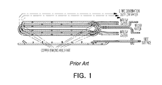
- FIG. 1 is an exemplary view illustrating a heating coil according to the related art.
- a heating coil according to the related art is a simple air-core type heating coil in which a coil and a cooling pipe are integrated.
- the heating coil has a large amount of heat and the coil has a small longitudinal cross sectional area.
- a cooling water intake and exhaust line is further disposed in the middle of the coil, a welding operation for branching intermediate cooling water is required. Therefore, a leakage current is frequent, and an electric current may flow in a weld area, so the weld area may be affected by surface resistance, which may frequently cause arc damage.
- An aspect of the present disclosure may provide a coil assembly for an induction heating device, improving a longitudinal cross sectional area of a coil, and preventing leakage of cooling water, and an induction heating device including the same.
- a coil assembly for an induction heating device includes a first coil part having a first cooling pipe insertion groove, indented into the inside thereof, in one surface, a first cooling pipe combined with the first cooling pipe insertion groove such that a portion of an outer surface is exposed, a second coil part disposed opposite to one surface of the first coil part provided with the first cooling pipe insertion groove, and having a second cooling pipe insertion groove, indented into the inside thereof, in one surface opposite to one surface of the first coil part, and a second cooling pipe combined with the second cooling pipe insertion groove such that a portion of an outer surface is exposed.
- the first coil part and the second coil part may include a plurality of heating conductors arranged side by side, and a connecting conductor connecting one ends of a heating conductor provided as the plurality of heating conductors to each other.
- the heating conductor and the connecting conductor of the first coil part may be disposed opposite to the heating conductor and the connecting conductor of the second coil part.
- the first cooling pipe and the second cooling pipe may be provided continuously in the heating conductor and the connecting conductor.
- the other end of the heating conductor of the first coil part and the second coil part may be provided with a coupling part for coupling the first coil part and the second coil part.
- the heating conductor of the first coil part may include a first heating conductor and a second heating conductor
- the heating conductor of the second coil part may include a third heating conductor and a fourth heating conductor, opposite to the first heating conductor and the second heating conductor, respectively
- the coupling part may be provided in the other end of the first heating conductor and the other end of the fourth heating conductor or the other end of the second heating conductor and the other end of the third heating conductor.
- the coupling part provided in the first coil part and the coupling part of the second coil part may be screw-coupled to each other.
- a gap between the coupling part provided in the first coil part and the coupling part provided in the second coil part may be provided with an insulating member.
- the first cooling pipe and the second cooling pipe may be disposed in the inside of the coupling part.
- the first cooling pipe insertion groove and the second cooling pipe insertion groove may be provided to have shapes corresponding to outer surfaces of the first cooling pipe and the second cooling pipe, respectively.
- the first cooling pipe and the second cooling pipe may be press-fit into the first cooling pipe insertion groove and the second cooling pipe insertion groove, respectively.
- an induction heating device includes the coil assembly for an induction heating device, a power supply coupled to a first coil part and a second coil part to supply AC power, and a cooling pump coupled to a first cooling pipe and a second cooling pipe to supply cooling water.
- the coil assembly for an induction heating device may be provided as a pair of coil assemblies for an induction heating device disposed to be spaced apart from each other, with a conductive plate passing between the pair of coil assemblies for an induction heating device.
- the coil assembly for an induction heating device may be disposed to intersect a direction in which the conductive plate is supplied.
- a weld zone is reduced in a coil, so heating efficiency may be improved and leakage may be prevented.
- FIG. 1 is an exemplary view illustrating a heating coil according to the related art.
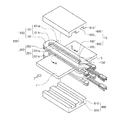
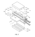
- FIG. 2 is a schematic exploded perspective view of a coil assembly for an induction heating device according to an exemplary embodiment.
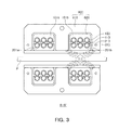
- FIG. 3 is a schematic cross-sectional view taken along line A-A′ of FIG. 2 .
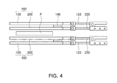
- FIG. 4 is a schematic side view of an induction heating device in which a core is detached from a coil assembly for an induction heating device according to an exemplary embodiment.
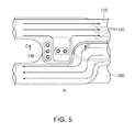
- FIG. 5 is a schematic enlarged view of portion B of FIG. 2 .
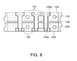
- FIG. 6 is a schematic cross-sectional view taken along line C-C′ of FIG. 5 .
- FIG. 2 is a schematic exploded perspective view of an induction heating device according to an exemplary embodiment
- FIG. 3 is a schematic cross-sectional view taken along line A-A′ of FIG. 2
- FIG. 4 is a schematic side view of an induction heating device in which a core is detached from an induction heating device according to an exemplary embodiment.
- an induction heating device 10 may include a coil assembly for an induction heating device 500 , a separate power supply applying AC power to the coil assembly for an induction heating device 500 , and a cooling pump coupled to the coil assembly for an induction heating device 500 and supplying cooling water.
- the coil assembly for an induction heating device 500 may include a first coil part 100 and a second coil part 200 , and a separate power supply (not shown) supplying AC power may be connected to the first coil part 100 and the second coil part 200 .
- the first coil part 100 may be provided to have a U-shape as a whole, and a material therefor may preferably be a metal material with high conductivity.
- the first coil part 100 may be formed of a 99% pure electrolytic tough pitch (ETP) copper wide flare material.
- a first cooling pipe insertion groove 110 indented into the inside thereof, may be provided.
- the first cooling pipe insertion groove 110 provided as at least one first cooling pipe insertion groove, may be continuously arranged along one surface of the first coil part 100 , and may be manufactured by cutting into one surface of the first coil part 100 , or may be manufactured at the same time as the first coil part 100 .
- a first cooling pipe 120 may be combined with the first cooling pipe insertion groove 110 .
- the first cooling pipe insertion groove 110 may be provided to have a shape corresponding to an outer surface of the first cooling pipe 120 , and the first cooling pipe 120 may be press-fitted into the first cooling pipe insertion groove 110 .
- a method in which the first cooling pipe is combined with the first cooling pipe insertion groove 110 is not limited to press-fitting, and various methods commonly used in the art to which the present invention belongs may be employed, such as welding, or the like.
- the first coil part 100 may include a plurality of heating conductors 101 arranged to intersect a direction in which a conductive plate P is supplied, and a connecting conductor 102 connecting one ends of a heating conductor 101 , by way of example.
- the direction in which the conductive plate P is supplied is indicated by an arrow and the letter ‘D’ in FIG. 2 .
- the heating conductor 101 may be provided as a plurality of heating conductors arranged side by side, and may include a first heating conductor 101 a and a second heating conductor 101 b, by way of example.
- heating conductor 101 may be provided with the connecting conductor 102 connecting two heating conductors 101 .
- the heating conductor 101 and the connecting conductor 102 may be manufactured as separate members and coupled together by a method such as welding, or the like, or may be integrally molded at the same time during manufacture.
- One surface of the first coil part 100 in detail, one surface of the heating conductor 101 and the connecting conductor 102 may be provided with the first cooling pipe insertion groove 110 , indented into the inside thereof.
- the first cooling pipe insertion groove 110 may be provided continuously along one surface of the first coil part 100 .
- the first cooling pipe insertion groove 110 may be provided continuously in one surface of the first heating conductor 101 a, the connecting conductor 102 , and the second heating conductor 101 b.
- a method of manufacturing the first cooling pipe insertion groove 110 may be a cutting machining process.
- the first cooling pipe insertion groove 110 for coupling of the first cooling pipe 120 is cutting machined in one surface of the first coil part 100 in advance, and the first cooling pipe 120 is press-fitted thereinto, the first cooling pipe 120 may be tightly coupled to the first coil part 100 during indentation.
- only a small amount of additional soldering and brazing operations may be required.
- a welding work area may be significantly reduced, and an effect of surface resistance, slightly increased by welding materials, may be not significant, so heating efficiency may be improved.
- a degree of current flowing to a weld zone of a cooling pipe is significantly reduced, so a risk caused by internal leakage may be reduced.
- stability of the use of a coil part in a harsh environment such as a steel processing line may be improved.
- At least one first cooling pipe 120 may be combined with the first cooling pipe insertion groove 110 .
- the first cooling pipe 120 may be combined with the first cooling pipe insertion groove 110 while a portion of an outer surface is exposed externally.
- a portion of an outer surface maybe exposed to one surface of the first cooling pipe insertion groove 110 .
- the first cooling pipe 120 may be provided continuously in one surface of the first coil part 100 along the first cooling pipe insertion groove 110 , and may be provided in a U-shape as a whole.
- the first cooling pipe 120 may be connected to a separate cooling pump (not shown), and the cooling pump may supply cooling water to the first cooling pipe 120 .
- the first cooling pipe 120 may allow the first coil part 100 , having been heated, to be cooled.
- the other end of the first coil part 100 that is, an end in which the connecting conductor 102 is not provided, may be provided with a coupling part 130 for coupling of the second coil part 200 which will be described later.
- the coupling part 130 may be coupled to a coupling part 230 of the second coil part 200 which will be described later, and a detailed description thereof will be provided later.
- the second coil part 200 may be disposed opposite to one surface of the first coil part 100 provided with the first cooling pipe insertion groove 110 , and one surface opposite to one surface of the first coil part 100 may be provided with a second cooling pipe insertion groove 210 , indented into the inside thereof.
- a second cooling pipe 220 may be combined with the second cooling pipe insertion groove 210 .
- a portion of an outer surface of the second cooling pipe 220 maybe exposed to one surface of the second coil part 200 .
- the outer surface of the first cooling pipe 120 having been exposed, may be provided to opposite to the outer surface of the second cooling pipe 220 , having been exposed.
- the second coil part 200 may include a third heating conductor 201 a and a fourth heating conductor 201 b opposite to the first heating conductor 101 a and the second heating conductor 101 b of the first coil part 100 , respectively, byway of example, and the third heating conductor 201 a and the fourth heating conductor 201 b may be connected by a connecting conductor 202 .
- the connecting conductor 202 may be disposed opposite to the connecting conductor 202 of the first coil part 100 .
- the second coil part 200 may be provided to have the same shape as that of the first coil part 100 described previously.
- the second coil part 200 maybe provided symmetrically with respect to the first coil part 200 based on the conductive plate P.
- the coupling parts 130 and 230 may be coupled to the first coil part 100 and the second coil part 200 , respectively. As the coupling parts 130 and 230 are screw-coupled, the first coil part 100 and the second coil part 200 may be coupled to each other.
- the coupling relationship between the first coil part 100 and the second coil part 200 will be described with reference to FIGS. 5 and 6 .
- FIG. 5 is an enlarged view of portion B of FIG. 2
- FIG. 6 is a schematic cross-sectional view taken along line C-C′ of FIG. 5 .
- the coupling parts 130 and 230 may be provided in the other end in which the connecting conductors 102 and 202 of the first coil part 100 and the second coil part 200 are not provided, respectively.
- the coupling parts 130 and 230 may be provided in the first heating conductor 101 a of the first coil part 100 and the fourth heating conductor 201 b of the second coil part 200 , or maybe provided in the second heating conductor 101 b of the first coil part 100 and the third heating conductor 201 a of the second coil part 200 .
- the coupling parts 130 and 230 of one heating conductor may be provided to protrude toward the other heating conductor, and a plurality of screw holes 130 a may be provided therein.
- a screw hole 130 a is provided with a male thread 131 and a female thread 132 , the first coil part 100 and the second coil part 200 are screw-coupled.
- an insulating member 140 may be provided between the coupling part 130 of the first coil part 100 and the coupling part 230 of the second coil part 200 .
- the insulating member 140 is provided as an insulator, thereby preventing a phenomenon in which the first coil part 100 and the second coil part 200 are electrically short-circuited.
- the insulating member 140 may be provided with at least one screw through hole 140 a.
- first cooling pipe 120 and the second cooling pipe 220 may be disposed in the coupling parts 130 and 230 .
- a cooling pipe passing through the heating conductors 101 and 201 may pass through the inside of the coupling parts 130 and 230 .
- the first cooling pipe 120 and the second cooling pipe 220 may be coupled to the coupling parts 130 and 230 .
- the first coil part 100 and the second coil part 200 are screw-coupled through the coupling part 130 .
- the first coil part 100 and the second coil part 200 may be easily coupled to each other without a brazing process performed by a skilled welding technician, and replacement and repair may be easily performed, as advantages.
- a core 600 may be coupled to the coil assembly for an induction heating device 500 to allow the other surface of the second coil part 200 , which is not opposite to the first coil part 100 , to be exposed externally.
- a body part 610 of the core 600 may be provided with an accommodating groove 620 indented into the inside thereof to accommodate the coil part.
- the accommodating groove 620 is provided in a U-shape as a whole, so the first coil part 100 and the second coil part 200 may be accommodated, and the other surface of the second coil part 200 may be exposed externally.
- the conductive plate P may pass below the other surface of the second coil part 200 , and the coil assembly for an induction heating device 500 may be disposed to intersect a direction in which a conductive plate is supplied.
- the coil assembly for an induction heating device 500 maybe provided as a pair of coil assemblies.
- the coil assembly for an induction heating device 500 may be provided as two coil assemblies as a pair, spaced apart from each other.
- the conductive plate P may pass between the coil assemblies for an induction heating device.
Landscapes
- Physics & Mathematics (AREA)
- Electromagnetism (AREA)
- Engineering & Computer Science (AREA)
- Power Engineering (AREA)
- General Induction Heating (AREA)
Applications Claiming Priority (3)
| Application Number | Priority Date | Filing Date | Title |
|---|---|---|---|
| KR1020150054070A KR101714869B1 (ko) | 2015-04-16 | 2015-04-16 | 유도 가열 장치용 코일 어셈블리 및 이를 포함하는 유도 가열 장치 |
| KR10-2015-0054070 | 2015-04-16 | ||
| PCT/KR2015/013268 WO2016167439A1 (ko) | 2015-04-16 | 2015-12-04 | 유도 가열 장치용 코일 어셈블리 및 이를 포함하는 유도 가열 장치 |
Publications (1)
| Publication Number | Publication Date |
|---|---|
| US20180098388A1 true US20180098388A1 (en) | 2018-04-05 |
Family
ID=57126894
Family Applications (1)
| Application Number | Title | Priority Date | Filing Date |
|---|---|---|---|
| US15/566,820 Abandoned US20180098388A1 (en) | 2015-04-16 | 2015-12-04 | Coil assembly for induction heating device and induction heating device comprising same |
Country Status (5)
| Country | Link |
|---|---|
| US (1) | US20180098388A1 (ko) |
| JP (1) | JP6457113B2 (ko) |
| KR (1) | KR101714869B1 (ko) |
| CN (1) | CN107548572A (ko) |
| WO (1) | WO2016167439A1 (ko) |
Cited By (2)
| Publication number | Priority date | Publication date | Assignee | Title |
|---|---|---|---|---|
| US10805879B2 (en) | 2018-09-27 | 2020-10-13 | Apple Inc. | Low-power activation of accessory in sleep state |
| US20220187020A1 (en) * | 2019-04-29 | 2022-06-16 | Rotelec Sa | Apparatus for heating metal products |
Families Citing this family (3)
| Publication number | Priority date | Publication date | Assignee | Title |
|---|---|---|---|---|
| KR102031865B1 (ko) * | 2018-02-13 | 2019-10-15 | 오세돈 | 이차전지 파우치 전극리드 밀봉장치 |
| KR20200075662A (ko) | 2018-12-18 | 2020-06-26 | 주식회사 포스코 | 유도가열장치 |
| KR102703162B1 (ko) * | 2022-03-02 | 2024-09-05 | (주)오성하이텍 | 높낮이가 다른 코어 부재를 포함하여 폭방향 균일한 가열을 보장하는 유도 가열 코일 |
Citations (8)
| Publication number | Priority date | Publication date | Assignee | Title |
|---|---|---|---|---|
| US3424886A (en) * | 1966-10-27 | 1969-01-28 | Ajax Magnethermic Corp | Induction heating |
| US5987054A (en) * | 1997-02-10 | 1999-11-16 | Inductotherm Corp. | Induction coil and coreless induction furnace employing same |
| JP2001300695A (ja) * | 2000-04-27 | 2001-10-30 | Nippon Steel Corp | 溶融金属の電磁攪拌用連続鋳造鋳型 |
| JP2002043042A (ja) * | 2000-07-31 | 2002-02-08 | Nippon Steel Corp | シングルターン型誘導加熱コイル |
| US20030164372A1 (en) * | 2000-08-29 | 2003-09-04 | Dieter Schluckebier | Device for inductively heating metallic strips |
| US20040256382A1 (en) * | 2001-06-26 | 2004-12-23 | Pilavdzic Jim Izudin | Apparatus for inductive and resistive heating of an object |
| US20090255924A1 (en) * | 2008-04-14 | 2009-10-15 | Jean Lovens | Variable Width Transverse Flux Electric Induction Coils |
| US20100181298A1 (en) * | 2007-06-14 | 2010-07-22 | Mtu Aero Engines Gmbh | Induction coil, method and device for the inductive heating of metal components |
Family Cites Families (11)
| Publication number | Priority date | Publication date | Assignee | Title |
|---|---|---|---|---|
| JPS621754Y2 (ko) * | 1981-04-09 | 1987-01-16 | ||
| JPH02189887A (ja) * | 1989-01-18 | 1990-07-25 | Matsushita Electric Ind Co Ltd | 高周波誘導加熱コイル |
| JPH09283269A (ja) * | 1996-04-10 | 1997-10-31 | Mitsubishi Heavy Ind Ltd | 誘導加熱装置 |
| JP3337122B2 (ja) * | 1997-10-27 | 2002-10-21 | 川崎製鉄株式会社 | 熱間圧延設備及び熱間圧延方法 |
| TW409486B (en) * | 1998-03-24 | 2000-10-21 | Toshiba Corp | Induction heating apparatus |
| JP3814490B2 (ja) * | 2001-03-30 | 2006-08-30 | Jfeスチール株式会社 | 誘導加熱装置の防熱板および誘導加熱装置 |
| JP2007316550A (ja) * | 2006-05-29 | 2007-12-06 | Kyocera Mita Corp | 定着装置 |
| KR100893620B1 (ko) * | 2007-04-10 | 2009-04-20 | 노창식 | 유도가열장치용 냉각코일 |
| JP5053169B2 (ja) * | 2008-05-14 | 2012-10-17 | 新日本製鐵株式会社 | 誘導加熱装置および誘導加熱方法 |
| JP5578325B2 (ja) * | 2010-11-19 | 2014-08-27 | 積水化学工業株式会社 | 電磁誘導加熱コイル、電磁誘導加熱装置及び金属体の加熱方法 |
| KR101428178B1 (ko) * | 2012-07-30 | 2014-08-07 | 주식회사 포스코 | 가열장치 및, 이를 포함하는 연속 금속판 가열 시스템 |
-
2015
- 2015-04-16 KR KR1020150054070A patent/KR101714869B1/ko active Active
- 2015-12-04 CN CN201580078851.0A patent/CN107548572A/zh active Pending
- 2015-12-04 JP JP2017553022A patent/JP6457113B2/ja active Active
- 2015-12-04 WO PCT/KR2015/013268 patent/WO2016167439A1/ko not_active Ceased
- 2015-12-04 US US15/566,820 patent/US20180098388A1/en not_active Abandoned
Patent Citations (8)
| Publication number | Priority date | Publication date | Assignee | Title |
|---|---|---|---|---|
| US3424886A (en) * | 1966-10-27 | 1969-01-28 | Ajax Magnethermic Corp | Induction heating |
| US5987054A (en) * | 1997-02-10 | 1999-11-16 | Inductotherm Corp. | Induction coil and coreless induction furnace employing same |
| JP2001300695A (ja) * | 2000-04-27 | 2001-10-30 | Nippon Steel Corp | 溶融金属の電磁攪拌用連続鋳造鋳型 |
| JP2002043042A (ja) * | 2000-07-31 | 2002-02-08 | Nippon Steel Corp | シングルターン型誘導加熱コイル |
| US20030164372A1 (en) * | 2000-08-29 | 2003-09-04 | Dieter Schluckebier | Device for inductively heating metallic strips |
| US20040256382A1 (en) * | 2001-06-26 | 2004-12-23 | Pilavdzic Jim Izudin | Apparatus for inductive and resistive heating of an object |
| US20100181298A1 (en) * | 2007-06-14 | 2010-07-22 | Mtu Aero Engines Gmbh | Induction coil, method and device for the inductive heating of metal components |
| US20090255924A1 (en) * | 2008-04-14 | 2009-10-15 | Jean Lovens | Variable Width Transverse Flux Electric Induction Coils |
Cited By (2)
| Publication number | Priority date | Publication date | Assignee | Title |
|---|---|---|---|---|
| US10805879B2 (en) | 2018-09-27 | 2020-10-13 | Apple Inc. | Low-power activation of accessory in sleep state |
| US20220187020A1 (en) * | 2019-04-29 | 2022-06-16 | Rotelec Sa | Apparatus for heating metal products |
Also Published As
| Publication number | Publication date |
|---|---|
| JP2018514910A (ja) | 2018-06-07 |
| CN107548572A (zh) | 2018-01-05 |
| WO2016167439A1 (ko) | 2016-10-20 |
| KR101714869B1 (ko) | 2017-03-10 |
| JP6457113B2 (ja) | 2019-01-23 |
| KR20160124327A (ko) | 2016-10-27 |
Similar Documents
| Publication | Publication Date | Title |
|---|---|---|
| KR101714869B1 (ko) | 유도 가열 장치용 코일 어셈블리 및 이를 포함하는 유도 가열 장치 | |
| AU2009273793B2 (en) | Electric induction edge heating of electrically conductive slabs | |
| US20170271074A1 (en) | Transformer structure | |
| KR20150036480A (ko) | 전봉관 용접 장치 | |
| CN103366933B (zh) | 一种一体化高频功率变压器 | |
| CN100391674C (zh) | 高频线路连接器的高频感应焊接方法 | |
| KR101833109B1 (ko) | 전봉관 용접 장치 | |
| CN217859217U (zh) | 一种楔形感应加热头 | |
| KR102031865B1 (ko) | 이차전지 파우치 전극리드 밀봉장치 | |
| CN108513385B (zh) | 过热水蒸气生成装置和用于该装置的导体管的制造方法 | |
| KR101442989B1 (ko) | 초전도 직류 리액터 | |
| JP6081181B2 (ja) | トランス用コアおよびトランス | |
| CN203366967U (zh) | 一种一体化高频功率变压器 | |
| US1834445A (en) | Inductor coil | |
| US10616960B2 (en) | Heating coil | |
| CN106783096A (zh) | 一种漏磁补偿结构 | |
| CN110121225B (zh) | 一种变频压缩机转子内孔加热用感应器 | |
| JP2013135106A (ja) | 電流補助部材およびこれを用いた電流補助アセンブリ | |
| KR101187323B1 (ko) | 고주파 유도가열기의 수랭식 트랜스포머 및 이의 제조방법 | |
| KR102095825B1 (ko) | 변압기용 권선 코일 및 단자 | |
| CN114619115B (zh) | 一种楔形感应加热头 | |
| JP2011238671A (ja) | 複合磁性素子 | |
| CN206902188U (zh) | 快速接头的感应器及淬火机床 | |
| US9147520B2 (en) | Dry-type transformer | |
| KR102427565B1 (ko) | 용접 트랜스 |
Legal Events
| Date | Code | Title | Description |
|---|---|---|---|
| AS | Assignment |
Owner name: POSCO, KOREA, REPUBLIC OF Free format text: ASSIGNMENT OF ASSIGNORS INTEREST;ASSIGNORS:JEONG, HEE-TAE;SUNG, BYOUNG-GEE;LEE, SANG-HYEON;AND OTHERS;REEL/FRAME:044210/0393 Effective date: 20171011 Owner name: PSTEK CO., LTD., KOREA, REPUBLIC OF Free format text: ASSIGNMENT OF ASSIGNORS INTEREST;ASSIGNORS:JEONG, HEE-TAE;SUNG, BYOUNG-GEE;LEE, SANG-HYEON;AND OTHERS;REEL/FRAME:044210/0393 Effective date: 20171011 |
|
| STPP | Information on status: patent application and granting procedure in general |
Free format text: DOCKETED NEW CASE - READY FOR EXAMINATION |
|
| STPP | Information on status: patent application and granting procedure in general |
Free format text: NON FINAL ACTION MAILED |
|
| STCB | Information on status: application discontinuation |
Free format text: ABANDONED -- FAILURE TO RESPOND TO AN OFFICE ACTION |