US20030192432A1 - Filter apparatus - Google Patents
Filter apparatus Download PDFInfo
- Publication number
- US20030192432A1 US20030192432A1 US10/120,743 US12074302A US2003192432A1 US 20030192432 A1 US20030192432 A1 US 20030192432A1 US 12074302 A US12074302 A US 12074302A US 2003192432 A1 US2003192432 A1 US 2003192432A1
- Authority
- US
- United States
- Prior art keywords
- filter
- fluid bed
- bundle
- movable
- transport mechanism
- Prior art date
- Legal status (The legal status is an assumption and is not a legal conclusion. Google has not performed a legal analysis and makes no representation as to the accuracy of the status listed.)
- Granted
Links
- 239000012530 fluid Substances 0.000 claims abstract description 70
- 230000007723 transport mechanism Effects 0.000 claims description 53
- 238000000034 method Methods 0.000 claims description 44
- 230000008569 process Effects 0.000 claims description 32
- 238000001914 filtration Methods 0.000 claims description 13
- 239000000463 material Substances 0.000 claims description 12
- 238000004140 cleaning Methods 0.000 claims description 6
- 239000013618 particulate matter Substances 0.000 claims description 5
- 230000007246 mechanism Effects 0.000 claims description 4
- 238000011112 process operation Methods 0.000 abstract description 3
- 230000000712 assembly Effects 0.000 description 9
- 238000000429 assembly Methods 0.000 description 9
- 239000002245 particle Substances 0.000 description 7
- 238000013461 design Methods 0.000 description 4
- 239000004033 plastic Substances 0.000 description 4
- 229920003023 plastic Polymers 0.000 description 4
- 239000000843 powder Substances 0.000 description 4
- 239000011230 binding agent Substances 0.000 description 3
- 239000008187 granular material Substances 0.000 description 3
- 238000012423 maintenance Methods 0.000 description 3
- 230000000737 periodic effect Effects 0.000 description 3
- 229910001220 stainless steel Inorganic materials 0.000 description 3
- 239000010935 stainless steel Substances 0.000 description 3
- LFQSCWFLJHTTHZ-UHFFFAOYSA-N Ethanol Chemical compound CCO LFQSCWFLJHTTHZ-UHFFFAOYSA-N 0.000 description 2
- 238000004891 communication Methods 0.000 description 2
- 239000000428 dust Substances 0.000 description 2
- 238000005469 granulation Methods 0.000 description 2
- 230000003179 granulation Effects 0.000 description 2
- 239000007788 liquid Substances 0.000 description 2
- 230000009972 noncorrosive effect Effects 0.000 description 2
- 239000002904 solvent Substances 0.000 description 2
- 239000000126 substance Substances 0.000 description 2
- 229920001875 Ebonite Polymers 0.000 description 1
- 230000015572 biosynthetic process Effects 0.000 description 1
- 230000008859 change Effects 0.000 description 1
- 239000003599 detergent Substances 0.000 description 1
- 238000007599 discharging Methods 0.000 description 1
- 239000003814 drug Substances 0.000 description 1
- 238000005516 engineering process Methods 0.000 description 1
- 239000004744 fabric Substances 0.000 description 1
- 238000010438 heat treatment Methods 0.000 description 1
- 229910052500 inorganic mineral Inorganic materials 0.000 description 1
- 238000009434 installation Methods 0.000 description 1
- 230000013011 mating Effects 0.000 description 1
- 239000002184 metal Substances 0.000 description 1
- 229910052751 metal Inorganic materials 0.000 description 1
- 150000002739 metals Chemical class 0.000 description 1
- 239000011707 mineral Substances 0.000 description 1
- 238000012986 modification Methods 0.000 description 1
- 230000004048 modification Effects 0.000 description 1
- 238000012545 processing Methods 0.000 description 1
- 239000000047 product Substances 0.000 description 1
- 238000009877 rendering Methods 0.000 description 1
- 239000007787 solid Substances 0.000 description 1
- 238000005507 spraying Methods 0.000 description 1
- 230000000087 stabilizing effect Effects 0.000 description 1
- 230000001960 triggered effect Effects 0.000 description 1
- 238000005406 washing Methods 0.000 description 1
- XLYOFNOQVPJJNP-UHFFFAOYSA-N water Substances O XLYOFNOQVPJJNP-UHFFFAOYSA-N 0.000 description 1
- 238000005550 wet granulation Methods 0.000 description 1
- 239000002023 wood Substances 0.000 description 1
Images


Classifications
-
- B—PERFORMING OPERATIONS; TRANSPORTING
- B01—PHYSICAL OR CHEMICAL PROCESSES OR APPARATUS IN GENERAL
- B01D—SEPARATION
- B01D46/00—Filters or filtering processes specially modified for separating dispersed particles from gases or vapours
- B01D46/02—Particle separators, e.g. dust precipitators, having hollow filters made of flexible material
- B01D46/04—Cleaning filters
-
- B—PERFORMING OPERATIONS; TRANSPORTING
- B01—PHYSICAL OR CHEMICAL PROCESSES OR APPARATUS IN GENERAL
- B01D—SEPARATION
- B01D46/00—Filters or filtering processes specially modified for separating dispersed particles from gases or vapours
- B01D46/24—Particle separators, e.g. dust precipitators, using rigid hollow filter bodies
- B01D46/2403—Particle separators, e.g. dust precipitators, using rigid hollow filter bodies characterised by the physical shape or structure of the filtering element
- B01D46/2411—Filter cartridges
-
- B—PERFORMING OPERATIONS; TRANSPORTING
- B01—PHYSICAL OR CHEMICAL PROCESSES OR APPARATUS IN GENERAL
- B01D—SEPARATION
- B01D46/00—Filters or filtering processes specially modified for separating dispersed particles from gases or vapours
- B01D46/66—Regeneration of the filtering material or filter elements inside the filter
- B01D46/70—Regeneration of the filtering material or filter elements inside the filter by acting counter-currently on the filtering surface, e.g. by flushing on the non-cake side of the filter
- B01D46/71—Regeneration of the filtering material or filter elements inside the filter by acting counter-currently on the filtering surface, e.g. by flushing on the non-cake side of the filter with pressurised gas, e.g. pulsed air
-
- B—PERFORMING OPERATIONS; TRANSPORTING
- B01—PHYSICAL OR CHEMICAL PROCESSES OR APPARATUS IN GENERAL
- B01D—SEPARATION
- B01D46/00—Filters or filtering processes specially modified for separating dispersed particles from gases or vapours
- B01D46/90—Devices for taking out of action one or more units of multi-unit filters, e.g. for regeneration or maintenance
-
- B—PERFORMING OPERATIONS; TRANSPORTING
- B01—PHYSICAL OR CHEMICAL PROCESSES OR APPARATUS IN GENERAL
- B01D—SEPARATION
- B01D2273/00—Operation of filters specially adapted for separating dispersed particles from gases or vapours
- B01D2273/14—Filters which are moved between two or more positions, e.g. by turning, pushing
-
- Y—GENERAL TAGGING OF NEW TECHNOLOGICAL DEVELOPMENTS; GENERAL TAGGING OF CROSS-SECTIONAL TECHNOLOGIES SPANNING OVER SEVERAL SECTIONS OF THE IPC; TECHNICAL SUBJECTS COVERED BY FORMER USPC CROSS-REFERENCE ART COLLECTIONS [XRACs] AND DIGESTS
- Y10—TECHNICAL SUBJECTS COVERED BY FORMER USPC
- Y10S—TECHNICAL SUBJECTS COVERED BY FORMER USPC CROSS-REFERENCE ART COLLECTIONS [XRACs] AND DIGESTS
- Y10S55/00—Gas separation
- Y10S55/46—Spray booths
Definitions
- the present invention relates generally to fluid bed granulators, coaters and dryers.
- the invention relates to a filter apparatus including a movable filter bundle that can be selectively raised and lowered to facilitate maintenance of one or more filter units on the movable filter bundle.
- Granulation is a crucial stage in many industries, such as mineral processing, agricultural products, detergents, pharmaceuticals, foodstuffs, and specialty chemicals. It is a size enlargement process where fine powder feed particles are bound together to form agglomerates or granules, a process that, for example, enables the formation of tablets.
- One type of granulation, wet granulation is a process where the particles are bound together by a fluid (also called a binder) which forms liquid bridges between the particles to hold them together.
- the binding fluid is usually a solvent, like water or ethanol, or a solution of a polymeric binder in a solvent.
- a fluid bed granulator is a tall cylindrical or rectangular vessel containing a bed of particles. Air is forced through a distributor at the base which fluidizes and agitates the powder. A binding fluid is added by spraying from above, below, or within the powder bed. These binder drops collide with the powder particles and form liquid bridges, which hold them together by capillary suction. By heating the fluidizing air, the product can be granulated and dried simultaneously, which is particularly useful in the specialty chemical and pharmaceutical industries.
- One such filter system is a bag filter system as illustrated in U.S. Pat. No. 5,446,974 to Gubler, herein incorporated by reference.
- the Gubler patent discloses a filter assembly having a cylindrical fluid bed chamber wherein the process air enters from one end, is filtered by one or more bag filters, and exits the opposite end.
- the bag filters are rigidly attached to a mounting plate within the filter plenum during operation and are unattached and removed from the filter assembly for servicing.
- the individual bag filters disclosed in the Gubler patent comprise flexible filter bags that are fitted over and clamped onto underlying rigid frames. During operation, the filter bags form around and through side bars of the rigid frame in an accordion shape. Periodic cleaning of the filter bags is achieved by applying a periodic pulse of reverse air to the bag filter, forcing the filter bag outward from the rigid frame and dislodging particulate matter that has accumulated on the filter bag. Although this is remarkably effective, the filter bag must be eventually removed and cleaned or replaced.
- the present invention relates generally to a filter apparatus for use with a fluid bed processor.
- the filter apparatus generally includes a fluid bed chamber, a filter mount transport mechanism within the fluid bed chamber, and a filter mount for receiving a filter.
- the filter mount transport mechanism typically has one or more filters attached to corresponding filter mounts on a support structure.
- the filter mount transport mechanism may also include an index rod that rotationally secures the filter mount transport mechanism when in the operational position. For example, in one embodiment of the invention, in a first position air is filtered through the filters in the process operation of the filter assembly and in a second position individual filters on the filter mount transport mechanism can be easily inspected, serviced, and/or replaced.
- the filter mount transport mechanism further comprises at least one filter unit to form a movable filter bundle.
- One preferred filter unit includes a rigid frame, flexible filter media positioned relative to the frame so that the flexible filter media extends at least partially through openings in the frame and into the rigid frame when the filter unit has process air flowing therethrough, and a mechanism to secure a portion of the flexible filter media to the rigid filter frame.
- This embodiment of the invention also may include a cleaning mechanism, intermediate to the outlet opening, for removing particulate matter accumulated on the flexible filter media by causing the flexible filter media to momentarily flex outwardly from the rigid frame such that the flexible filter media extends substantially outside the openings.
- One such cleaning mechanism is a blow down tube.
- the filter mount transport mechanism further comprises an index rod.
- the filter apparatus also further comprises at least one index rod receiver, such as a tube or ring, attached to the fluid bed chamber.
- the index rod receiver is configured to receive the index rod and thereby rotationally secure the filter mount transport mechanism in a desired orientation while in the first position.
- the number of index rod receivers equals the number of filter units to ensure a desired alignment between the filter units and other elements of the filter assembly, such as blow down tubes.
- One method for servicing a filter in a fluid bed system comprises first providing a fluid bed chamber within a filter apparatus, the fluid bed chamber having a movable filter bundle in a first position within the fluid bed chamber, the movable filter bundle having at least one filter attached thereto.
- a portion of the fluid bed chamber is swung outward away from the fluid bed system and a product container is removed, thereby creating a filter servicing open space.
- the movable filter bundle is then moved to a second position within the fluid bed chamber. In this second position the filter is inspected, serviced, and/or replaced.
- the first position comprises a raised position within the fluid bed chamber wherein the filter apparatus can be operational to filter process air and the second position comprises a lowered position within the fluid bed chamber wherein the at least one filter can be easily accessed for service.
- servicing the filter can comprise refurbishing a reusable bag filter unit by removing the filter unit from the movable filter bundle, removing the bag filter media from a substantially rigid frame, applying a different bag filter media to the substantially rigid frame, thereby refurbishing the filter, and attaching the refurbished filter to the movable filter bundle.
- the method can comprise simply changing filters by removing a filter from the movable filter bundle and attaching a different filter to the movable filter bundle.
- Yet another embodiment involves replacing the bag filter media on an underlying rigid frame that remains attached to the filter mount transport mechanism.
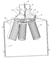
- FIG. 1 is a filter assembly according to one embodiment of the invention
- FIG. 2 is a view of component a filter assembly according to one embodiment of the invention.
- FIG. 3 is another view of a filter assembly according to one embodiment of the invention.
- FIG. 4 is a view of another component of a filter assembly according to one embodiment of the invention.
- FIG. 5 is a view of yet another component of a filter assembly according to one embodiment of the invention.
- FIG. 6 is yet another view of a component of a filter assembly according to one embodiment of the invention.
- FIG. 7 is yet another view of a component of a filter assembly according to one embodiment of the invention.
- the present invention relates to improved filter assemblies for use with fluid bed systems.
- the assemblies generally comprise a filter mount transport mechanism that can be selectively moved to first and second positions, for example raised and lowered positions, within a fluid bed chamber.
- first and second positions for example raised and lowered positions
- filters attached to the filter mount transport mechanism In the first position air is filtered through filters attached to the filter mount transport mechanism in the process operation of the filter assembly.
- the second position the individual filters can be quickly inspected, serviced, and/or replaced.
- filter assemblies in accordance with the present invention minimize the fluid bed system down time that is required to service filter assemblies.
- Such filter assemblies in accordance with the present invention are easier to service than conventional filter assemblies because they require simpler and faster procedures for filter servicing. For example, it is often difficult to access filters in conventional filter assemblies and significant portions of the fluid bed system must often be disassembled in order to access the filters for servicing, whereas the filter assembly of the present invention has an easily accessible filter bundle when it is in the second position.
- FIG. 1 depicts one embodiment of a fluid bed system 10 .
- fluid bed system 10 can be conceptually divided into one or more regions or chambers. The illustrated embodiment shows five such regions: exhaust plenum 12 , filter housing chamber 14 , expansion chamber 16 , product container 18 , and inlet plenum 20 . At times it will also be useful to refer to fluid bed chamber 17 , which includes both filter housing chamber 14 and expansion chamber 16 . These regions will be discussed in further detail hereinbelow, although some regions relate more to the present invention than others and will therefore receive more discussion.
- Inlet plenum 20 is the location where process air enters fluid bed system 10 and is directed upwards towards filter housing chamber 14 .
- the process air is used to maintain particulate matter in the fluid bed system in a fluidized state.
- Product container 18 is a conical chamber where at least a portion of the fluidized bed is located while the fluid bed system 10 is in operation. When fluid bed system 10 is not in operation, product granules settle out of the fluidized state and are collected in the product container. According to one embodiment of the invention, product container 18 is attached to a movable cart 21 so that it can be quickly separated from fluid bed system 10 , allowing removal of product granules that have accumulated in product container 18 and exposing an open space between inlet plenum 20 and fluid bed chamber 17 .
- a vacuum is formed within fluid bed system 10 by of a fan (not illustrated) located at the upper end of the fluid bed chamber 17 .
- the inlet for the bonding solution used in the granulating process is preferably located within expansion chamber 16 .
- filter housing chamber 14 within filter housing chamber 14 is filter mount transport mechanism 22 .
- Filter housing chamber 14 is open to expansion chamber 16 below, and has an opening above, where filter mount transport mechanism 22 sealingly attaches.
- Exhaust plenum 12 , filter housing chamber 14 , expansion chamber 16 , product container 18 , and inlet plenum 20 can each be formed of any of a variety of materials that do not easily corrode and do not react unfavorably with the materials used in the granulating.
- stainless steel and plastic are often suitable, as well as combinations of stainless steel, plastic, and other non-corrosive materials.
- one skilled in the art will recognize that the details presented herein with respect to exhaust plenum 12 , filter housing chamber 14 , expansion chamber 16 , product container 18 , and inlet plenum 20 are illustrative of a preferred embodiment only, and are not limiting of the invention.
- FIG. 1 illustrates filter mount transport mechanism 22 (and movable filter bundle 23 ) in the first position 24 .
- filter mount transport mechanism describes a movable device, of which a filter may or may not be a part.
- movable filter bundle is used to denote a filter mount transport mechanism 22 that includes one or more filters and that can be moved between two or more positions. Accordingly, in the first position 24 , as illustrated in FIG. 1, the top surface of filter mount transport mechanism 22 is positioned at the intersection of filter housing chamber 14 and exhaust plenum 12 so that filter mount transport mechanism 22 is housed substantially within filter housing chamber 14 .
- a support assembly is used to support filter mount transport mechanism 22 in either the first or second position.
- the support assembly may comprise a cable 28 that is in communication with filter mount transport mechanism 22 .
- the support assembly may comprise a belt, chain, rod, or other structure that permits movement of the filter mount transport mechanism 22 between the first and second positions.
- a variety of devices can be used in conjunction with the support assembly to effectuate movement of filter mount transport mechanism 22 , including pulleys, motors, cranks, and the like.
- expansion chamber 16 can be swung away from fluid bed system 10 on a hinge 34 , leaving an open space.
- product container 18 sits on cart 21 , as illustrated in FIG. 1, and can be removed completely. The combination of swinging expansion chamber 16 away from fluid bed system 10 and removing product container 18 creates a filter servicing open space 36 .
- filter mount transport mechanism 22 can be selectively moved by support assembly to a first position 24 and a second position 26 so that the top surface of filter mount transport mechanism 22 is positioned either within filter housing chamber 14 (the first position) or within filter servicing open space 36 (the second position).
- filter servicing open space 36 is formed by swinging expansion chamber 16 away from fluid bed system 10 and removing product container 18 . The filter mount transport mechanism 22 is thereby made easily accessible to a filter assembly operator for filter servicing.
- the filter assembly In the first position of the illustrated embodiment of FIG. 1, the filter assembly is in operational mode for filtering process air through the assembly whereas in the second position of FIG. 3 the filter assembly is in maintenance mode for maintaining and/or inspecting the filter units 29 .
- Compatible filters include both single-use and reusable filter units.
- Single-use filter units can be quickly and easily replaced whereas reusable filter units can be quickly and easily maintained by removing the spent filter units and either refurbishing them or replacing them with new or previously refurbished filter units.
- the Gubler patent discloses a filter unit assembly that generally comprises a rigid filter frame, a filter bag, a clamp, and a gasket.
- the rigid filter frame comprises a cylindrical device having a generally flat top, a flat bottom, and parallel filter frame rods between the top and the bottom.
- the filter top has a plate covering part of the filter top and a threaded rod that allows the filter frame to be attached to a mount on a filter assembly, such as filter mount 44 in FIG. 4.
- the top also has one or more openings to allow air to flow through the filter.
- the filter bottom is a solid plate that provides support for the filter frame rods.
- the filter frame rods have one end on the perimeter of the top plate and the other end on the perimeter of the bottom plate, allowing the side rods to form the shape of the side wall of the filter frame assembly.
- the filter frame is generally reusable and can be made of a variety of ridged materials, such as plastics, metals, hard rubber, and wood, so long as they are sturdy. Additionally, the filter frame can vary in size and shape to fit the required filtering applications.
- the filter bag has an open top allowing the filter bag, during installation, to be pulled upward over the filter frame until the bottom media of the filter bag is tight against the filter bottom plate.
- the filter bag has numerous pleats to allow the filter bag to expand in the cleaning process and contract during normal operation.
- process air is exerted against it during operation of the filter assembly, the filter bag forms around and through the rigid filter frame rods in a manner which provides increased filter surface area in a minimal space.
- particulate matter gradually coats the surface of the filter bag, rendering it less effective.
- a pulse of reverse air flow is applied against the outlet side of the filter bag, it causes the bag to flex outward away from the filter frame, thereby discharging the coated particles off the outer fabric. This can be done without stopping the filtering process.
- the filter bags of the Gubler patent can be removed from the frame and washed in a washing machine to clean before reusing.
- the clamp holds the filter bag in place at the top of the filter assembly.
- the clamp tightens around the perimeter of the filter frame and filter bag causing the filter bag to be held in a fixed position at the top of the filter assembly.
- a gasket is also employed to ensure the filter assembly forms a tight seal against the filter mount.
- filter mount transport mechanism 22 comprises a support structure 40 that serves as a unifying member of filter mount transport mechanism 22 , connecting each of seal 42 , filter mounts 44 , index rod 46 , and attachment block 48 into a cohesive unit.
- the particular configuration of support structure 40 is not critical, so long as it provides adequate strength to support the weight of the various components of filter mount transport mechanism 22 and prevents the passage of air except through openings 49 in filter mounts 44 .
- support structure 40 can be formed of any suitable material that does not corrode while in contact with process materials.
- suitable materials may include stainless steel, plastic, other non-corrosive materials, and combinations thereof.
- filter mounts 44 will vary depending on the particular filter unit used, but may comprise, for example, a filter receiving member comprising a threaded bore for receiving a threaded screw on a filter unit.
- filter mounts 44 can be permanently attached to at least a portion of the corresponding filters so that only part of each filter, such as the filtering media, is removed for filter servicing.
- five filter mounts are depicted in FIG. 3, one skilled in the art will recognize that the number of mounts can be altered to accommodate the filtering requirements of the filtering assembly. For example, one, two, three, four, or six mounts may also be used.
- Index rod 46 and attachment block 48 illustrate two embodiments of elements to connect filter mount transport mechanism 22 to fluid bed system 10 .
- Index rod 46 acts as a stabilizing rod that fixes filter mount transport mechanism 22 into a desired rotational position when in the first position 24 by mating with an index rod receiver 60 on fluid bed system 10 , as depicted in FIG. 5. While in the lowered position index rod 46 is no longer mated with index rod receiver 60 so movable filter bundle 23 is not rotationally restricted. Thus, an operator can easily rotate movable filter bundle 23 to access the desired filter.
- FIG. 5 is a top view of fluid bed system 10 in FIG. 1.
- index rod receivers 60 comprise a series of openings configured in a circular pattern around a center axis.
- the number of index rod receivers 60 is equal to the number of filter mounts 44 and filter units 29 so that regardless of which index rod receiver 60 is mated with index rod 46 , each of filter mounts 44 and filter unit 29 are positioned in the desired orientation with respect to fluid bed system 10 and blow down tubes 64 as depicted in FIGS. 6 and 7.
- index rod 46 is positioned off center from the center of filter mount transport mechanism 22 a distance corresponding to the distance from the center of a grouping of index rod receivers 60 to the center of one of index rod receivers 60 . This enables index rod 46 and each of index rod receiver 60 to connect if they are in line as they are brought together.
- index rod receiver 60 may comprise a plurality of tubes sized to fit index rod 46
- the index rod receiver 60 may comprise rings or non enclosed structures, such as U-shaped members.
- the exact shape of the index rod receiver 60 is not critical, so long as they rotationally secure index rod 46 , and thus movable filter bundle 23 , in a desired position.
- the designs of the present invention are particularly advantageous in that it is not necessary for index rod 46 to be in any particular degree of rotation as it is raised to be inserted into one of the index rod receivers 60 because it will necessarily align with one of them.
- attachment block 48 includes a cable attachment aperture 50 to which cable 28 attaches.
- the cable attachment aperture 50 is centered in the filter mount transport mechanism 22 so that it acts as a single support locus for the entire filter mount transport mechanism 22 and the weight is evenly distributed around the periphery thereof.
- the support assembly is not limited to a cable 28 but can comprise various other assemblies that can be used to raise and lower filter mount transport mechanism 22 . Therefore, other structures than cable attachment aperture 50 and attachment block 48 can be used to provide a suitable assembly for attaching the support assembly to filter mount transport mechanism 22 .
- a non-exclusive list of examples includes a clamp, a hook, and/or a plurality of support assembly attachment members located on a plurality of locations on filter mount transport mechanism 22 .
- cable 28 is attached to attachment block 48 at cable attachment aperture 50 and passes through cable guide tube 30 , located on exhaust plenum 12 .
- the cable 28 passes through pulley mount 32 to a corresponding pulley (not illustrated) positioned thereon.
- the cable 28 can be attached to the pulley, which has a motor, crank, or other device acting thereon.
- cable 28 can extend above pulley mount 32 and exhaust plenum 12 for attachment to a motor, crank, or other device outside exhaust plenum 12 .
- FIG. 6 is a top view of exhaust plenum 12 and FIG. 7 is a perspective view of exhaust plenum 12 .
- the exhaust plenum 12 comprises a dome section 62 and a cylindrical section 63 attached thereover.
- a plurality of blow down tubes 64 are attached to cylindrical section 63 .
- Blow down tubes 64 are in communication with additional tubing and a blower system (not illustrated) that coordinates sequential blow downs to each of blow down tubes 64 on a predetermined timing schedule.
- the positioning of blow down tubes 64 is preferably such that when index rod 46 is mated with one of index rod receivers 60 , each blow down tube aligns with one of the filters attached to filter mount transport mechanism 22 .
- the purpose of aligning filter units 29 with blow down tubes 64 is so that fluid bed system 10 has the ability to periodically clean itself of blinding process material. This is performed by applying a pulse of reverse air through blow down tubes 64 to the outlet side of each filter unit 29 , causing the filter bag to flex outward from the center of the assembly frame. This pulse of air serves to dislodge blinding particles that have accumulated on filter units 29 as described hereinabove. This is preferably done in an alternating manner so that only one filter is subject to the pulse of reverse air at any given time. The timing of the air pulses is triggered by an automatic periodic timing device that coordinates with a valve manifold.
- Actuator 66 is attached to either the upper lip of filter housing chamber 14 or directly to dome section 62 . According to one embodiment of the invention, actuator 66 coordinates with filter mount transport mechanism 22 and exhaust plenum 12 to ensure that seal 42 forms a tight seal between filter mount transport mechanism 22 and exhaust plenum 12 .
- a filter apparatus as described hereinabove is provided with a fluid bed chamber within the filter apparatus.
- a movable filter bundle, having at least one filter attached thereto, is provided in a first position within the fluid bed chamber.
- the first position within the fluid bed chamber is one wherein the filter apparatus can be operational to filter process air and a second position is one wherein at least one filter on movable filter bundle 23 can be easily accessed for service.
- the first position be an elevated position and the second position be a lowered position
- the first and second positions can be in different relations to each other, such as horizontal to each other or with the second position being the raised position. Nevertheless, for purposes of simplicity only the embodiment having the first position elevated with respect to the second position is further referred to herein.
- the at least one filter is a filter unit that can be selectively attached and removed from the movable filter assembly.
- the filter unit is removed from the movable filter assembly and a new or refurbished filter unit is attached. This is repeated for each filter on movable filter bundle 23 .
- movable filter bundle 23 is freely rotatable in the lowered position.
- an operator of fluid bed system 10 can rotate movable filter bundle 23 to sequentially remove and attach the respective used and new filters.
- the filter comprises a filter unit having a rigid frame with a plurality of openings and a filter media covering the plurality of openings.
- a filter is described in the Gubler patent, incorporated hereinabove by reference.
- the steps to replacing such a filter preferably include removing the at least one filter from movable filter bundle 23 , removing the filter media from the substantially rigid frame, applying a different filter media to the substantially rigid frame, thereby refurbishing the filter, and attaching the refurbished filter to movable filter bundle 23 .
- such a filter can be serviced by removing and replacing the filter media while the underlying rigid frame remains attached to the filter mount transport mechanism.
- the support assembly is moved, thereby raising movable filter bundle 23 to the first position.
- index rod 46 is mated with any of the index rod receiver 60 on exhaust plenum 12 , thus rotationally securing movable filter bundle 23 for operation.
Landscapes
- Chemical & Material Sciences (AREA)
- Chemical Kinetics & Catalysis (AREA)
- Physics & Mathematics (AREA)
- Geometry (AREA)
- Filtering Of Dispersed Particles In Gases (AREA)
- Separation By Low-Temperature Treatments (AREA)
- Control And Other Processes For Unpacking Of Materials (AREA)
- Water Treatment By Sorption (AREA)
- Glanulating (AREA)
- External Artificial Organs (AREA)
- Surgical Instruments (AREA)
- Centrifugal Separators (AREA)
Abstract
Description
- 1. The Field of the Invention
- The present invention relates generally to fluid bed granulators, coaters and dryers. In particular, the invention relates to a filter apparatus including a movable filter bundle that can be selectively raised and lowered to facilitate maintenance of one or more filter units on the movable filter bundle.
- 2. The Relevant Technology
- Granulation is a crucial stage in many industries, such as mineral processing, agricultural products, detergents, pharmaceuticals, foodstuffs, and specialty chemicals. It is a size enlargement process where fine powder feed particles are bound together to form agglomerates or granules, a process that, for example, enables the formation of tablets. One type of granulation, wet granulation, is a process where the particles are bound together by a fluid (also called a binder) which forms liquid bridges between the particles to hold them together. The binding fluid is usually a solvent, like water or ethanol, or a solution of a polymeric binder in a solvent.
- A fluid bed granulator is a tall cylindrical or rectangular vessel containing a bed of particles. Air is forced through a distributor at the base which fluidizes and agitates the powder. A binding fluid is added by spraying from above, below, or within the powder bed. These binder drops collide with the powder particles and form liquid bridges, which hold them together by capillary suction. By heating the fluidizing air, the product can be granulated and dried simultaneously, which is particularly useful in the specialty chemical and pharmaceutical industries.
- As a result of the processes, fluid bed granulators, coaters, and dryers create a large amount of dust that fills the process air used therein. In order to prevent the release of this dust to the environment these devices therefore require the use of filter systems.
- One such filter system is a bag filter system as illustrated in U.S. Pat. No. 5,446,974 to Gubler, herein incorporated by reference. The Gubler patent discloses a filter assembly having a cylindrical fluid bed chamber wherein the process air enters from one end, is filtered by one or more bag filters, and exits the opposite end. The bag filters are rigidly attached to a mounting plate within the filter plenum during operation and are unattached and removed from the filter assembly for servicing.
- The individual bag filters disclosed in the Gubler patent comprise flexible filter bags that are fitted over and clamped onto underlying rigid frames. During operation, the filter bags form around and through side bars of the rigid frame in an accordion shape. Periodic cleaning of the filter bags is achieved by applying a periodic pulse of reverse air to the bag filter, forcing the filter bag outward from the rigid frame and dislodging particulate matter that has accumulated on the filter bag. Although this is remarkably effective, the filter bag must be eventually removed and cleaned or replaced.
- Of course, a variety of other filter assemblies, filters, and bag filters exist that can also be effectively used to filter process air. With each of these filter systems the degree of difficulty in cleaning or replacing a filter in a fluid bed system can increase costs and limit the operational time of the filter system and its corresponding fluid bed system.
- The present invention relates generally to a filter apparatus for use with a fluid bed processor. The filter apparatus generally includes a fluid bed chamber, a filter mount transport mechanism within the fluid bed chamber, and a filter mount for receiving a filter. The filter mount transport mechanism typically has one or more filters attached to corresponding filter mounts on a support structure. The filter mount transport mechanism may also include an index rod that rotationally secures the filter mount transport mechanism when in the operational position. For example, in one embodiment of the invention, in a first position air is filtered through the filters in the process operation of the filter assembly and in a second position individual filters on the filter mount transport mechanism can be easily inspected, serviced, and/or replaced.
- According to one embodiment of the invention the filter mount transport mechanism further comprises at least one filter unit to form a movable filter bundle. One preferred filter unit includes a rigid frame, flexible filter media positioned relative to the frame so that the flexible filter media extends at least partially through openings in the frame and into the rigid frame when the filter unit has process air flowing therethrough, and a mechanism to secure a portion of the flexible filter media to the rigid filter frame. This embodiment of the invention also may include a cleaning mechanism, intermediate to the outlet opening, for removing particulate matter accumulated on the flexible filter media by causing the flexible filter media to momentarily flex outwardly from the rigid frame such that the flexible filter media extends substantially outside the openings. One such cleaning mechanism is a blow down tube.
- According to another embodiment of the invention the filter mount transport mechanism further comprises an index rod. In this embodiment the filter apparatus also further comprises at least one index rod receiver, such as a tube or ring, attached to the fluid bed chamber. The index rod receiver is configured to receive the index rod and thereby rotationally secure the filter mount transport mechanism in a desired orientation while in the first position. Preferably, the number of index rod receivers equals the number of filter units to ensure a desired alignment between the filter units and other elements of the filter assembly, such as blow down tubes.
- One method for servicing a filter in a fluid bed system according to the invention comprises first providing a fluid bed chamber within a filter apparatus, the fluid bed chamber having a movable filter bundle in a first position within the fluid bed chamber, the movable filter bundle having at least one filter attached thereto. Optionally, a portion of the fluid bed chamber is swung outward away from the fluid bed system and a product container is removed, thereby creating a filter servicing open space. The movable filter bundle is then moved to a second position within the fluid bed chamber. In this second position the filter is inspected, serviced, and/or replaced.
- According to one aspect of this embodiment of the invention, the first position comprises a raised position within the fluid bed chamber wherein the filter apparatus can be operational to filter process air and the second position comprises a lowered position within the fluid bed chamber wherein the at least one filter can be easily accessed for service.
- Servicing the filter can comprise refurbishing a reusable bag filter unit by removing the filter unit from the movable filter bundle, removing the bag filter media from a substantially rigid frame, applying a different bag filter media to the substantially rigid frame, thereby refurbishing the filter, and attaching the refurbished filter to the movable filter bundle. Alternatively, the method can comprise simply changing filters by removing a filter from the movable filter bundle and attaching a different filter to the movable filter bundle. Yet another embodiment involves replacing the bag filter media on an underlying rigid frame that remains attached to the filter mount transport mechanism.
- These and other features of the present invention will become more fully apparent from the following description and appended claims, or may be learned by the practice of the invention as set forth hereinafter.
- In order to more fully understand the manner in which the above-recited and other advantages and objects of the invention are obtained, a more particular description of the invention will be rendered by reference to specific embodiments thereof which are illustrated in the appended drawings. Understanding that these drawings depict only typical embodiments of the invention and are not therefore to be considered as limiting of its scope, the invention will be described and explained with additional specificity and detail through the use of accompanying drawings in which:
- FIG. 1 is a filter assembly according to one embodiment of the invention;
- FIG. 2 is a view of component a filter assembly according to one embodiment of the invention;
- FIG. 3 is another view of a filter assembly according to one embodiment of the invention;
- FIG. 4 is a view of another component of a filter assembly according to one embodiment of the invention;
- FIG. 5 is a view of yet another component of a filter assembly according to one embodiment of the invention;
- FIG. 6 is yet another view of a component of a filter assembly according to one embodiment of the invention; and
- FIG. 7 is yet another view of a component of a filter assembly according to one embodiment of the invention.
- The present invention relates to improved filter assemblies for use with fluid bed systems. The assemblies generally comprise a filter mount transport mechanism that can be selectively moved to first and second positions, for example raised and lowered positions, within a fluid bed chamber. In the first position air is filtered through filters attached to the filter mount transport mechanism in the process operation of the filter assembly. In the second position the individual filters can be quickly inspected, serviced, and/or replaced. Thus, filter assemblies in accordance with the present invention minimize the fluid bed system down time that is required to service filter assemblies.
- Such filter assemblies in accordance with the present invention are easier to service than conventional filter assemblies because they require simpler and faster procedures for filter servicing. For example, it is often difficult to access filters in conventional filter assemblies and significant portions of the fluid bed system must often be disassembled in order to access the filters for servicing, whereas the filter assembly of the present invention has an easily accessible filter bundle when it is in the second position.
- Additional advantages of the present invention will become readily apparent to those skilled in the art from the following detailed description, wherein currently preferred embodiments of the invention are shown and described in the disclosure. As will be realized, the invention is capable of other and different embodiments, and its several details are capable of modifications in various obvious respects, all without departing from the invention. Accordingly, the drawings and description are to be regarded as illustrative in nature, and not as restrictive.
- In the following description, numerous specific details are set forth in order to provide a thorough understanding of the present invention. It will be obvious, however, to one skilled in the art that the present invention may be practiced without these specific details. In other instances, well known aspects of fluidized bed and filtering processes and machinery have not been described in particular detail in order to avoid unnecessarily obscuring the present invention.
- It is to be understood that the drawings, wherein like structures are provided with like reference designations, are diagrammatic and schematic representations of embodiments of the present invention and are not necessarily drawn to scale. In addition, the drawings only show the structures necessary to understand illustrations of the present invention. Additional structures known in the art have not been included to maintain the clarity of the drawings.
- Referring now to the drawings, wherein like structures are provided with like reference designations, FIG. 1 depicts one embodiment of a
fluid bed system 10. For example, and not by way of limitation,fluid bed system 10 can be conceptually divided into one or more regions or chambers. The illustrated embodiment shows five such regions:exhaust plenum 12, filterhousing chamber 14,expansion chamber 16,product container 18, andinlet plenum 20. At times it will also be useful to refer tofluid bed chamber 17, which includes both filterhousing chamber 14 andexpansion chamber 16. These regions will be discussed in further detail hereinbelow, although some regions relate more to the present invention than others and will therefore receive more discussion. -
Inlet plenum 20 is the location where process air entersfluid bed system 10 and is directed upwards towardsfilter housing chamber 14. The process air is used to maintain particulate matter in the fluid bed system in a fluidized state. -
Product container 18 is a conical chamber where at least a portion of the fluidized bed is located while thefluid bed system 10 is in operation. Whenfluid bed system 10 is not in operation, product granules settle out of the fluidized state and are collected in the product container. According to one embodiment of the invention,product container 18 is attached to amovable cart 21 so that it can be quickly separated fromfluid bed system 10, allowing removal of product granules that have accumulated inproduct container 18 and exposing an open space betweeninlet plenum 20 andfluid bed chamber 17. - After leaving
product container 18, air travels upwards throughexpansion chamber 16, intofilter housing chamber 14, and exits throughexhaust plenum 12. In one embodiment a vacuum is formed withinfluid bed system 10 by of a fan (not illustrated) located at the upper end of thefluid bed chamber 17. Also, the inlet for the bonding solution used in the granulating process is preferably located withinexpansion chamber 16. - As illustrated in greater detail in FIG. 2, within
filter housing chamber 14 is filtermount transport mechanism 22.Filter housing chamber 14 is open toexpansion chamber 16 below, and has an opening above, where filter mounttransport mechanism 22 sealingly attaches. -
Exhaust plenum 12, filterhousing chamber 14,expansion chamber 16,product container 18, andinlet plenum 20 can each be formed of any of a variety of materials that do not easily corrode and do not react unfavorably with the materials used in the granulating. By way of non-limiting example, stainless steel and plastic are often suitable, as well as combinations of stainless steel, plastic, and other non-corrosive materials. In addition, one skilled in the art will recognize that the details presented herein with respect toexhaust plenum 12, filterhousing chamber 14,expansion chamber 16,product container 18, andinlet plenum 20 are illustrative of a preferred embodiment only, and are not limiting of the invention. - FIG. 1 illustrates filter mount transport mechanism 22 (and movable filter bundle 23) in the
first position 24. As used herein, the term “filter mount transport mechanism” describes a movable device, of which a filter may or may not be a part. Also as used herein, the term “movable filter bundle” is used to denote a filtermount transport mechanism 22 that includes one or more filters and that can be moved between two or more positions. Accordingly, in thefirst position 24, as illustrated in FIG. 1, the top surface of filter mounttransport mechanism 22 is positioned at the intersection offilter housing chamber 14 andexhaust plenum 12 so that filter mounttransport mechanism 22 is housed substantially withinfilter housing chamber 14. - A support assembly is used to support filter
mount transport mechanism 22 in either the first or second position. As illustrated in FIG. 3, the support assembly may comprise acable 28 that is in communication with filtermount transport mechanism 22. Alternatively, by way of non-limiting example, the support assembly may comprise a belt, chain, rod, or other structure that permits movement of the filtermount transport mechanism 22 between the first and second positions. In addition, a variety of devices can be used in conjunction with the support assembly to effectuate movement of filter mounttransport mechanism 22, including pulleys, motors, cranks, and the like. - As also illustrated on FIG. 3,
expansion chamber 16 can be swung away fromfluid bed system 10 on ahinge 34, leaving an open space. In addition,product container 18 sits oncart 21, as illustrated in FIG. 1, and can be removed completely. The combination of swingingexpansion chamber 16 away fromfluid bed system 10 and removingproduct container 18 creates a filter servicingopen space 36. - Thus, filter mount
transport mechanism 22 can be selectively moved by support assembly to afirst position 24 and asecond position 26 so that the top surface of filter mounttransport mechanism 22 is positioned either within filter housing chamber 14 (the first position) or within filter servicing open space 36 (the second position). Before filter mounttransport mechanism 22 can be moved tosecond position 26, however, filter servicingopen space 36 is formed by swingingexpansion chamber 16 away fromfluid bed system 10 and removingproduct container 18. The filter mounttransport mechanism 22 is thereby made easily accessible to a filter assembly operator for filter servicing. - In the first position of the illustrated embodiment of FIG. 1, the filter assembly is in operational mode for filtering process air through the assembly whereas in the second position of FIG. 3 the filter assembly is in maintenance mode for maintaining and/or inspecting the
filter units 29. - Compatible filters include both single-use and reusable filter units. Single-use filter units can be quickly and easily replaced whereas reusable filter units can be quickly and easily maintained by removing the spent filter units and either refurbishing them or replacing them with new or previously refurbished filter units.
- One compatible reusable filter unit assembly is described in U.S. Pat. No. 5,446,974 to Gubler (hereinafter “the Gubler patent”), previously incorporated herein by reference. This filter unit assembly is described hereinbelow to provide a description of one compatible device. Nevertheless, one skilled in the art will appreciate that a variety of filter unit designs can be utilized with the present invention, including both removable and permanently attached filter units.
- Accordingly, the Gubler patent discloses a filter unit assembly that generally comprises a rigid filter frame, a filter bag, a clamp, and a gasket. The rigid filter frame comprises a cylindrical device having a generally flat top, a flat bottom, and parallel filter frame rods between the top and the bottom. The filter top has a plate covering part of the filter top and a threaded rod that allows the filter frame to be attached to a mount on a filter assembly, such as filter mount 44 in FIG. 4. The top also has one or more openings to allow air to flow through the filter. The filter bottom is a solid plate that provides support for the filter frame rods. The filter frame rods have one end on the perimeter of the top plate and the other end on the perimeter of the bottom plate, allowing the side rods to form the shape of the side wall of the filter frame assembly. The filter frame is generally reusable and can be made of a variety of ridged materials, such as plastics, metals, hard rubber, and wood, so long as they are sturdy. Additionally, the filter frame can vary in size and shape to fit the required filtering applications.
- The filter bag has an open top allowing the filter bag, during installation, to be pulled upward over the filter frame until the bottom media of the filter bag is tight against the filter bottom plate. The filter bag has numerous pleats to allow the filter bag to expand in the cleaning process and contract during normal operation. When process air is exerted against it during operation of the filter assembly, the filter bag forms around and through the rigid filter frame rods in a manner which provides increased filter surface area in a minimal space. During usage, particulate matter gradually coats the surface of the filter bag, rendering it less effective. Advantageously, when a pulse of reverse air flow is applied against the outlet side of the filter bag, it causes the bag to flex outward away from the filter frame, thereby discharging the coated particles off the outer fabric. This can be done without stopping the filtering process. Eventually, the filter bags of the Gubler patent can be removed from the frame and washed in a washing machine to clean before reusing.
- The clamp holds the filter bag in place at the top of the filter assembly. The clamp tightens around the perimeter of the filter frame and filter bag causing the filter bag to be held in a fixed position at the top of the filter assembly. A gasket is also employed to ensure the filter assembly forms a tight seal against the filter mount.
- One reason the Gubler filter bags are advantageous is that they can be changed in minutes whereas many other conventional filter bag systems can take several hours to change. Thus, the combination of the presently disclosed
movable filter bundle 23 with the Gubler filter bags provides an even quicker filter maintenance system. Nevertheless, other conventional filter designs, both reusable and single-use, are compatible with themovable filter bundle 23 of the present invention. - Referring now to FIG. 4, according to one embodiment of the invention filter
mount transport mechanism 22 comprises asupport structure 40 that serves as a unifying member of filter mounttransport mechanism 22, connecting each ofseal 42, filter mounts 44,index rod 46, andattachment block 48 into a cohesive unit. The particular configuration ofsupport structure 40 is not critical, so long as it provides adequate strength to support the weight of the various components of filter mounttransport mechanism 22 and prevents the passage of air except throughopenings 49 in filter mounts 44. As with each of the components of thefluid bed system 10,support structure 40 can be formed of any suitable material that does not corrode while in contact with process materials. For example, suitable materials may include stainless steel, plastic, other non-corrosive materials, and combinations thereof. - The particular design of filter mounts 44 will vary depending on the particular filter unit used, but may comprise, for example, a filter receiving member comprising a threaded bore for receiving a threaded screw on a filter unit. Alternatively, filter mounts 44 can be permanently attached to at least a portion of the corresponding filters so that only part of each filter, such as the filtering media, is removed for filter servicing. Although five filter mounts are depicted in FIG. 3, one skilled in the art will recognize that the number of mounts can be altered to accommodate the filtering requirements of the filtering assembly. For example, one, two, three, four, or six mounts may also be used.
-
Index rod 46 andattachment block 48 illustrate two embodiments of elements to connect filtermount transport mechanism 22 tofluid bed system 10.Index rod 46 acts as a stabilizing rod that fixes filter mounttransport mechanism 22 into a desired rotational position when in thefirst position 24 by mating with anindex rod receiver 60 onfluid bed system 10, as depicted in FIG. 5. While in the loweredposition index rod 46 is no longer mated withindex rod receiver 60 somovable filter bundle 23 is not rotationally restricted. Thus, an operator can easily rotatemovable filter bundle 23 to access the desired filter. - FIG. 5 is a top view of
fluid bed system 10 in FIG. 1. As illustrated therein,index rod receivers 60 comprise a series of openings configured in a circular pattern around a center axis. Preferably, the number ofindex rod receivers 60 is equal to the number of filter mounts 44 andfilter units 29 so that regardless of whichindex rod receiver 60 is mated withindex rod 46, each of filter mounts 44 andfilter unit 29 are positioned in the desired orientation with respect tofluid bed system 10 and blow downtubes 64 as depicted in FIGS. 6 and 7. - Accordingly,
index rod 46 is positioned off center from the center of filter mount transport mechanism 22 a distance corresponding to the distance from the center of a grouping ofindex rod receivers 60 to the center of one ofindex rod receivers 60. This enablesindex rod 46 and each ofindex rod receiver 60 to connect if they are in line as they are brought together. - Although
index rod receiver 60 may comprise a plurality of tubes sized to fitindex rod 46, theindex rod receiver 60 may comprise rings or non enclosed structures, such as U-shaped members. The exact shape of theindex rod receiver 60 is not critical, so long as they rotationallysecure index rod 46, and thusmovable filter bundle 23, in a desired position. Thus, the designs of the present invention are particularly advantageous in that it is not necessary forindex rod 46 to be in any particular degree of rotation as it is raised to be inserted into one of theindex rod receivers 60 because it will necessarily align with one of them. - According to one embodiment of the invention, as illustrated in FIGS. 1-4,
attachment block 48 includes acable attachment aperture 50 to whichcable 28 attaches. Thecable attachment aperture 50 is centered in the filtermount transport mechanism 22 so that it acts as a single support locus for the entire filtermount transport mechanism 22 and the weight is evenly distributed around the periphery thereof. - Of course, as discussed hereinabove the support assembly is not limited to a
cable 28 but can comprise various other assemblies that can be used to raise and lower filtermount transport mechanism 22. Therefore, other structures thancable attachment aperture 50 andattachment block 48 can be used to provide a suitable assembly for attaching the support assembly to filtermount transport mechanism 22. A non-exclusive list of examples includes a clamp, a hook, and/or a plurality of support assembly attachment members located on a plurality of locations on filtermount transport mechanism 22. - Referring again now to FIG. 2, according to one embodiment of the invention,
cable 28 is attached to attachment block 48 atcable attachment aperture 50 and passes throughcable guide tube 30, located onexhaust plenum 12. Thecable 28 passes throughpulley mount 32 to a corresponding pulley (not illustrated) positioned thereon. Thecable 28 can be attached to the pulley, which has a motor, crank, or other device acting thereon. Alternatively,cable 28 can extend abovepulley mount 32 andexhaust plenum 12 for attachment to a motor, crank, or other device outsideexhaust plenum 12. - FIG. 6 is a top view of
exhaust plenum 12 and FIG. 7 is a perspective view ofexhaust plenum 12. Theexhaust plenum 12 comprises adome section 62 and acylindrical section 63 attached thereover. A plurality of blow downtubes 64 are attached tocylindrical section 63. Blow downtubes 64 are in communication with additional tubing and a blower system (not illustrated) that coordinates sequential blow downs to each of blow downtubes 64 on a predetermined timing schedule. The positioning of blow downtubes 64 is preferably such that whenindex rod 46 is mated with one ofindex rod receivers 60, each blow down tube aligns with one of the filters attached to filtermount transport mechanism 22. - The purpose of aligning
filter units 29 with blow downtubes 64 is so thatfluid bed system 10 has the ability to periodically clean itself of blinding process material. This is performed by applying a pulse of reverse air through blow downtubes 64 to the outlet side of eachfilter unit 29, causing the filter bag to flex outward from the center of the assembly frame. This pulse of air serves to dislodge blinding particles that have accumulated onfilter units 29 as described hereinabove. This is preferably done in an alternating manner so that only one filter is subject to the pulse of reverse air at any given time. The timing of the air pulses is triggered by an automatic periodic timing device that coordinates with a valve manifold. -
Actuator 66 is attached to either the upper lip offilter housing chamber 14 or directly todome section 62. According to one embodiment of the invention,actuator 66 coordinates with filtermount transport mechanism 22 andexhaust plenum 12 to ensure thatseal 42 forms a tight seal between filter mounttransport mechanism 22 andexhaust plenum 12. - Accordingly, one preferred method of operating the invention is as follows. First, a filter apparatus as described hereinabove is provided with a fluid bed chamber within the filter apparatus. A movable filter bundle, having at least one filter attached thereto, is provided in a first position within the fluid bed chamber. The first position within the fluid bed chamber is one wherein the filter apparatus can be operational to filter process air and a second position is one wherein at least one filter on
movable filter bundle 23 can be easily accessed for service. Although it is preferred that the first position be an elevated position and the second position be a lowered position, one skilled in the art will recognize that the first and second positions can be in different relations to each other, such as horizontal to each other or with the second position being the raised position. Nevertheless, for purposes of simplicity only the embodiment having the first position elevated with respect to the second position is further referred to herein. - For servicing, the process air entering the filter apparatus is stopped and the
expansion chamber 16 is swung onhinge 34 to the open position andcart 21 is removed along withproduct container 18. As a result, filter servicingopen space 36 is formed.Movable filter bundle 23 is then moved to the second position within filter servicingopen space 36. In this manner,movable filter bundle 23 is made readily accessible to an operator and the filter(s) can be inspected, serviced, and/or replaced. - According to one embodiment of the invention the at least one filter is a filter unit that can be selectively attached and removed from the movable filter assembly. Thus, after the movable filter assembly is lowered, the filter unit is removed from the movable filter assembly and a new or refurbished filter unit is attached. This is repeated for each filter on
movable filter bundle 23. - In those embodiments wherein support assembly incorporates a
flexible cable 28,movable filter bundle 23 is freely rotatable in the lowered position. Thus, an operator offluid bed system 10 can rotatemovable filter bundle 23 to sequentially remove and attach the respective used and new filters. - According to one embodiment of the invention, the filter comprises a filter unit having a rigid frame with a plurality of openings and a filter media covering the plurality of openings. One example of such a filter is described in the Gubler patent, incorporated hereinabove by reference. The steps to replacing such a filter preferably include removing the at least one filter from
movable filter bundle 23, removing the filter media from the substantially rigid frame, applying a different filter media to the substantially rigid frame, thereby refurbishing the filter, and attaching the refurbished filter tomovable filter bundle 23. Alternatively, such a filter can be serviced by removing and replacing the filter media while the underlying rigid frame remains attached to the filter mount transport mechanism. - After the replacement of all the filters is completed, the support assembly is moved, thereby raising
movable filter bundle 23 to the first position. In thisposition index rod 46 is mated with any of theindex rod receiver 60 onexhaust plenum 12, thus rotationally securingmovable filter bundle 23 for operation. - The present invention may be embodied in other specific forms without departing from its spirit or essential characteristics. The described embodiments are to be considered in all respects only as illustrative and not restrictive. The scope of the invention is, therefore, indicated by the appended claims rather than by the foregoing description. All changes which come within the meaning and range of equivalency of the claims are to be embraced within their scope.
Claims (26)
Priority Applications (13)
| Application Number | Priority Date | Filing Date | Title |
|---|---|---|---|
| US10/120,743 US6733574B2 (en) | 2002-04-11 | 2002-04-11 | Filter apparatus |
| IL16427203A IL164272A0 (en) | 2002-04-11 | 2003-01-13 | Filter apparatus |
| CNB038081547A CN1319623C (en) | 2002-04-11 | 2003-01-13 | filter |
| DE03746526T DE03746526T1 (en) | 2002-04-11 | 2003-01-13 | FILTER APPARATUS |
| AT03746526T ATE365067T1 (en) | 2002-04-11 | 2003-01-13 | FILTER DEVICE |
| BR0308804-9A BR0308804A (en) | 2002-04-11 | 2003-01-13 | Filter apparatus |
| AU2003262160A AU2003262160A1 (en) | 2002-04-11 | 2003-01-13 | Filter apparatus |
| EP03746526A EP1492608B1 (en) | 2002-04-11 | 2003-01-13 | Filter apparatus |
| CA002478316A CA2478316C (en) | 2002-04-11 | 2003-01-13 | Filter apparatus |
| DE60314503T DE60314503T2 (en) | 2002-04-11 | 2003-01-13 | FILTER DEVICE |
| PCT/US2003/000830 WO2003086582A1 (en) | 2002-04-11 | 2003-01-13 | Filter apparatus |
| MXPA04009731A MXPA04009731A (en) | 2002-04-11 | 2003-01-13 | Filter apparatus. |
| JP2003583589A JP2005530601A (en) | 2002-04-11 | 2003-01-13 | Filtration device |
Applications Claiming Priority (1)
| Application Number | Priority Date | Filing Date | Title |
|---|---|---|---|
| US10/120,743 US6733574B2 (en) | 2002-04-11 | 2002-04-11 | Filter apparatus |
Publications (2)
| Publication Number | Publication Date |
|---|---|
| US20030192432A1 true US20030192432A1 (en) | 2003-10-16 |
| US6733574B2 US6733574B2 (en) | 2004-05-11 |
Family
ID=28790156
Family Applications (1)
| Application Number | Title | Priority Date | Filing Date |
|---|---|---|---|
| US10/120,743 Expired - Lifetime US6733574B2 (en) | 2002-04-11 | 2002-04-11 | Filter apparatus |
Country Status (12)
| Country | Link |
|---|---|
| US (1) | US6733574B2 (en) |
| EP (1) | EP1492608B1 (en) |
| JP (1) | JP2005530601A (en) |
| CN (1) | CN1319623C (en) |
| AT (1) | ATE365067T1 (en) |
| AU (1) | AU2003262160A1 (en) |
| BR (1) | BR0308804A (en) |
| CA (1) | CA2478316C (en) |
| DE (2) | DE03746526T1 (en) |
| IL (1) | IL164272A0 (en) |
| MX (1) | MXPA04009731A (en) |
| WO (1) | WO2003086582A1 (en) |
Cited By (13)
| Publication number | Priority date | Publication date | Assignee | Title |
|---|---|---|---|---|
| EP1796812A4 (en) * | 2004-08-20 | 2008-11-05 | Deseret Lab Inc | MOBILE FILTER SYSTEM |
| US20110155052A1 (en) * | 2008-08-05 | 2011-06-30 | Iwao Fusejima | Fluidized bed apparatus |
| US20130232932A1 (en) * | 2012-03-12 | 2013-09-12 | General Electric Company | Pre-filter or coalescer mounted on pulse cartridge tripod |
| US20140082910A1 (en) * | 2012-09-21 | 2014-03-27 | 37Degree Filters, Inc. | Method of exchanging a filter assembly |
| US20150306531A1 (en) * | 2014-04-25 | 2015-10-29 | Pall Corporation | Processes for removing entrained particulates from a gas |
| US20170197171A1 (en) * | 2016-01-12 | 2017-07-13 | Green Energy Engineering Consultancy Limited | Acoustic aided air filter and a method of air filtration thereof |
| US9943787B2 (en) | 2010-09-21 | 2018-04-17 | Hubb Filters, Inc. | Method of filtering a liquid with a filter assembly having a primary and a secondary filter |
| US9987575B2 (en) | 2009-03-18 | 2018-06-05 | Hubb Filters, Inc. | Filter and method for filtering a liquid |
| CN111841442A (en) * | 2020-07-14 | 2020-10-30 | 上海凯宝健康科技有限公司 | A material boiling drying equipment for the production of granules |
| CN113566370A (en) * | 2021-06-23 | 2021-10-29 | 海南经贸职业技术学院 | Household artificial intelligence equipment based on computer internet of things control |
| US11491430B2 (en) | 2018-06-04 | 2022-11-08 | Glatt Gmbh | Filter unit |
| CN117686433A (en) * | 2024-02-03 | 2024-03-12 | 内蒙古北科交大机器人有限公司 | Infrared gas detection equipment based on hanging rail inspection robot |
| CN120714339A (en) * | 2025-08-28 | 2025-09-30 | 山东天源饲料有限公司 | An energy-saving control device for pulse dust collector in feed factory |
Families Citing this family (22)
| Publication number | Priority date | Publication date | Assignee | Title |
|---|---|---|---|---|
| SE0401183D0 (en) * | 2003-12-04 | 2004-05-06 | Electrolux Ab | Filter cleaning system for a vacuum cleaner |
| EP2373351B1 (en) * | 2008-12-31 | 2016-08-24 | American Sterilizer Company | Circulation and disposal device for multi-purpose sterilization chambers and washing chambers |
| JP5435974B2 (en) * | 2009-01-30 | 2014-03-05 | アマノ株式会社 | Filter device and granular material processing device |
| JP5363889B2 (en) * | 2009-06-25 | 2013-12-11 | フロイント産業株式会社 | Fluidized bed equipment |
| DE102009057205B4 (en) * | 2009-11-26 | 2014-08-21 | Herbert Hüttlin | Filter for dedusting process air from a process apparatus and process apparatus with such a filter |
| KR101371650B1 (en) * | 2012-08-31 | 2014-03-07 | 고려대학교 산학협력단 | Filter replacement apparatus for superconducting magnetic separator |
| CN104128151B (en) * | 2014-07-31 | 2016-05-04 | 贵州远盛钾业科技有限公司 | A kind of neutralization reaction still |
| CN105498628B (en) * | 2014-09-26 | 2018-02-09 | 中山市中智药业集团有限公司 | A kind of ultrafine powder capturing device for fluidized bed granulation system |
| US9756999B2 (en) | 2014-12-22 | 2017-09-12 | Aktiebolaget Electrolux | Vacuum cleaner filtration system with filter cleaning mode |
| DE202015105378U1 (en) * | 2015-01-22 | 2015-10-19 | Jens Neumann | Filter and filter changing device |
| CN105169820B (en) * | 2015-07-27 | 2017-01-18 | 宁波市江东知新机电设计有限公司 | Noise-reduction type air purification apparatus |
| CN105032073B (en) * | 2015-07-27 | 2016-09-14 | 宁波市江东知新机电设计有限公司 | A kind of air cleaner with air intake valve |
| CN105056645B (en) * | 2015-07-27 | 2016-07-13 | 宁波市江东知新机电设计有限公司 | A kind of air cleaner being conveniently replaceable drainage screen |
| CN105032072B (en) * | 2015-07-27 | 2016-09-28 | 宁波市江东知新机电设计有限公司 | A kind of air cleaner of adjustable speed |
| CN105032075B (en) * | 2015-07-31 | 2017-03-01 | 重庆市巴南区前进机械厂 | A kind of stable emission-control equipment |
| CN105032050B (en) * | 2015-07-31 | 2016-08-31 | 晋江市晋美日用品有限公司 | A kind of noise reduction and controlled emission-control equipment |
| CN105032052B (en) * | 2015-07-31 | 2016-08-17 | 盐城新安洲药业有限公司 | A kind of intelligent emission-control equipment |
| CN105032049B (en) * | 2015-07-31 | 2016-08-24 | 南安市蒂巧工艺品有限公司 | A kind of intelligent emission-control equipment being easy to clean |
| CN105148640B (en) * | 2015-07-31 | 2016-12-14 | 重庆界威模具股份有限公司 | A kind of easy-to-mount emission-control equipment |
| CN105080238B (en) * | 2015-07-31 | 2017-03-08 | 厦门市优家品日用品有限公司 | A kind of emission-control equipment of convenient cleaning |
| CN105126489B (en) * | 2015-07-31 | 2016-10-26 | 江苏凯威药用包装有限公司 | A kind of emission-control equipment of easy access |
| CN105477948B (en) * | 2015-12-16 | 2019-10-29 | 重庆市科旭制药机械设备制造有限公司 | A kind of cloth bag disc assembly of fast assembling-disassembling |
Citations (27)
| Publication number | Priority date | Publication date | Assignee | Title |
|---|---|---|---|---|
| US1761377A (en) * | 1926-08-28 | 1930-06-03 | Ass Lead Mfg Ltd | Apparatus for collecting suspended dust |
| US1797812A (en) * | 1928-09-04 | 1931-03-24 | Ass Lead Mfg Ltd | Apparatus for separating suspended matter from fluids |
| US4046526A (en) * | 1976-01-12 | 1977-09-06 | Aerodyne Development Corporation | Bag collector for dirt with selective half-bag cleaning |
| US4198216A (en) * | 1977-06-29 | 1980-04-15 | Ab Svenska Flaktfabriken | Arrangement for the exchange of filter elements |
| US4218227A (en) * | 1975-07-28 | 1980-08-19 | Donaldson Company, Inc. | Dust collector |
| US4277260A (en) * | 1979-08-14 | 1981-07-07 | Browning Jesse H | Powder collectors |
| US4309200A (en) * | 1980-09-02 | 1982-01-05 | The Air Preheater Company, Inc. | Baghouse with collapsible bag filter assembly |
| US4322231A (en) * | 1980-06-16 | 1982-03-30 | Farr Company | Filter element locking mechanism |
| US4331459A (en) * | 1980-10-10 | 1982-05-25 | Donaldson Company, Inc. | Self-cleaning pulsed air cleaner |
| US4336035A (en) * | 1979-03-12 | 1982-06-22 | Wheelabrator-Frye Inc. | Dust collector and filter bags therefor |
| US4345922A (en) * | 1980-12-22 | 1982-08-24 | Donaldson Company, Inc. | Air cleaner with anti-reentrainment |
| US4395269A (en) * | 1981-09-30 | 1983-07-26 | Donaldson Company, Inc. | Compact dust filter assembly |
| US4401445A (en) * | 1981-03-17 | 1983-08-30 | Jesse Browning | Method for converting a liquid paint spray booth to a powder paint spray booth |
| US4498913A (en) * | 1983-10-06 | 1985-02-12 | Nordson Corporation | Apparatus for filtering air for a powder spray booth |
| US4645520A (en) * | 1984-07-20 | 1987-02-24 | Huettlin Herbert | Filter assembly for dust removal from gases, especially in fluidized bed apparatus |
| US4670993A (en) * | 1984-08-16 | 1987-06-09 | E.C.C. America Inc. | Method for fluidizing fine kaolin particles |
| US4738696A (en) * | 1987-07-16 | 1988-04-19 | Staffeld Richard W | Baghouse installations |
| US4861353A (en) * | 1987-12-07 | 1989-08-29 | E. I. Du Pont De Nemours And Company | Filter element and assembly |
| US4953308A (en) * | 1989-02-06 | 1990-09-04 | Vector Corporation | Filter system for a fluid bed granulator/dryer |
| US5017200A (en) * | 1989-10-02 | 1991-05-21 | Inco Limited | Baghouse |
| US5115578A (en) * | 1991-03-05 | 1992-05-26 | Vector Corporation | Discharge mechanism for a large fluid bed/dryer granulator |
| US5171339A (en) * | 1991-11-07 | 1992-12-15 | E. I. Du Pont De Nemours And Company | Filter bag for hot gases |
| US5251384A (en) * | 1991-06-28 | 1993-10-12 | Glatt Air Techniques, Inc. | Fluidized bed apparatus including double chamber cartridge filter system |
| US5320657A (en) * | 1993-04-30 | 1994-06-14 | Dana Corporation | Staggered short pleat air filter |
| US5446974A (en) * | 1993-09-23 | 1995-09-05 | Gubler; Scott A. | Compact flexible filter assembly for a fluid bed granulator, coater and dryer |
| US5695536A (en) * | 1995-11-09 | 1997-12-09 | Nova Verta International S.P.A. | Apparatus for the positioning and the movement of the filtering ceiling of spray paint booths |
| US5993519A (en) * | 1997-07-25 | 1999-11-30 | Samsung Electronics Co., Ltd. | Method of exchanging filters in a clean room and auxiliary device for use in the exchanging of the filters |
Family Cites Families (9)
| Publication number | Priority date | Publication date | Assignee | Title |
|---|---|---|---|---|
| JPS5082978U (en) * | 1973-12-05 | 1975-07-16 | ||
| JPS51110766A (en) | 1975-03-22 | 1976-09-30 | Hiisu Fuirutoreeshon Ltd | Fuirutaa suriibu |
| JPS58112425U (en) * | 1981-09-11 | 1983-08-01 | 株式会社奈良機械製作所 | Filter tube removal device for bag filter device |
| JPS58132522U (en) * | 1982-03-03 | 1983-09-07 | 冨士産業株式会社 | Suspension of "filter" cloth in powder processing machine, vibration device |
| JPS60128717A (en) | 1983-12-16 | 1985-07-09 | Toshiba Corp | Integrated circuit device |
| JPS60176240U (en) * | 1984-04-26 | 1985-11-21 | 山之内製薬株式会社 | Fluidized bed granulator cleaning equipment |
| DE3941321C2 (en) * | 1989-12-14 | 1993-10-14 | Herbert Huettlin | Filter arrangement for dedusting gases |
| JPH04243511A (en) | 1991-01-28 | 1992-08-31 | Matsushita Electric Works Ltd | Dust collecting filter of dust collector |
| JPH0677682B2 (en) * | 1991-06-26 | 1994-10-05 | 田辺製薬株式会社 | Fluidized bed granulation dryer cleaning device and cleaning method |
-
2002
- 2002-04-11 US US10/120,743 patent/US6733574B2/en not_active Expired - Lifetime
-
2003
- 2003-01-13 DE DE03746526T patent/DE03746526T1/en active Pending
- 2003-01-13 CN CNB038081547A patent/CN1319623C/en not_active Expired - Fee Related
- 2003-01-13 CA CA002478316A patent/CA2478316C/en not_active Expired - Fee Related
- 2003-01-13 IL IL16427203A patent/IL164272A0/en not_active IP Right Cessation
- 2003-01-13 EP EP03746526A patent/EP1492608B1/en not_active Expired - Lifetime
- 2003-01-13 AT AT03746526T patent/ATE365067T1/en not_active IP Right Cessation
- 2003-01-13 BR BR0308804-9A patent/BR0308804A/en not_active Application Discontinuation
- 2003-01-13 AU AU2003262160A patent/AU2003262160A1/en not_active Abandoned
- 2003-01-13 MX MXPA04009731A patent/MXPA04009731A/en active IP Right Grant
- 2003-01-13 DE DE60314503T patent/DE60314503T2/en not_active Expired - Lifetime
- 2003-01-13 JP JP2003583589A patent/JP2005530601A/en active Pending
- 2003-01-13 WO PCT/US2003/000830 patent/WO2003086582A1/en not_active Ceased
Patent Citations (28)
| Publication number | Priority date | Publication date | Assignee | Title |
|---|---|---|---|---|
| US1761377A (en) * | 1926-08-28 | 1930-06-03 | Ass Lead Mfg Ltd | Apparatus for collecting suspended dust |
| US1797812A (en) * | 1928-09-04 | 1931-03-24 | Ass Lead Mfg Ltd | Apparatus for separating suspended matter from fluids |
| US4218227A (en) * | 1975-07-28 | 1980-08-19 | Donaldson Company, Inc. | Dust collector |
| US4046526A (en) * | 1976-01-12 | 1977-09-06 | Aerodyne Development Corporation | Bag collector for dirt with selective half-bag cleaning |
| US4198216A (en) * | 1977-06-29 | 1980-04-15 | Ab Svenska Flaktfabriken | Arrangement for the exchange of filter elements |
| US4336035A (en) * | 1979-03-12 | 1982-06-22 | Wheelabrator-Frye Inc. | Dust collector and filter bags therefor |
| US4277260A (en) * | 1979-08-14 | 1981-07-07 | Browning Jesse H | Powder collectors |
| US4322231A (en) * | 1980-06-16 | 1982-03-30 | Farr Company | Filter element locking mechanism |
| US4309200A (en) * | 1980-09-02 | 1982-01-05 | The Air Preheater Company, Inc. | Baghouse with collapsible bag filter assembly |
| US4331459A (en) * | 1980-10-10 | 1982-05-25 | Donaldson Company, Inc. | Self-cleaning pulsed air cleaner |
| US4345922A (en) * | 1980-12-22 | 1982-08-24 | Donaldson Company, Inc. | Air cleaner with anti-reentrainment |
| US4401445A (en) * | 1981-03-17 | 1983-08-30 | Jesse Browning | Method for converting a liquid paint spray booth to a powder paint spray booth |
| US4395269B1 (en) * | 1981-09-30 | 1994-08-30 | Donaldson Co Inc | Compact dust filter assembly |
| US4395269A (en) * | 1981-09-30 | 1983-07-26 | Donaldson Company, Inc. | Compact dust filter assembly |
| US4498913A (en) * | 1983-10-06 | 1985-02-12 | Nordson Corporation | Apparatus for filtering air for a powder spray booth |
| US4645520A (en) * | 1984-07-20 | 1987-02-24 | Huettlin Herbert | Filter assembly for dust removal from gases, especially in fluidized bed apparatus |
| US4670993A (en) * | 1984-08-16 | 1987-06-09 | E.C.C. America Inc. | Method for fluidizing fine kaolin particles |
| US4738696A (en) * | 1987-07-16 | 1988-04-19 | Staffeld Richard W | Baghouse installations |
| US4861353A (en) * | 1987-12-07 | 1989-08-29 | E. I. Du Pont De Nemours And Company | Filter element and assembly |
| US4953308A (en) * | 1989-02-06 | 1990-09-04 | Vector Corporation | Filter system for a fluid bed granulator/dryer |
| US5017200A (en) * | 1989-10-02 | 1991-05-21 | Inco Limited | Baghouse |
| US5115578A (en) * | 1991-03-05 | 1992-05-26 | Vector Corporation | Discharge mechanism for a large fluid bed/dryer granulator |
| US5251384A (en) * | 1991-06-28 | 1993-10-12 | Glatt Air Techniques, Inc. | Fluidized bed apparatus including double chamber cartridge filter system |
| US5171339A (en) * | 1991-11-07 | 1992-12-15 | E. I. Du Pont De Nemours And Company | Filter bag for hot gases |
| US5320657A (en) * | 1993-04-30 | 1994-06-14 | Dana Corporation | Staggered short pleat air filter |
| US5446974A (en) * | 1993-09-23 | 1995-09-05 | Gubler; Scott A. | Compact flexible filter assembly for a fluid bed granulator, coater and dryer |
| US5695536A (en) * | 1995-11-09 | 1997-12-09 | Nova Verta International S.P.A. | Apparatus for the positioning and the movement of the filtering ceiling of spray paint booths |
| US5993519A (en) * | 1997-07-25 | 1999-11-30 | Samsung Electronics Co., Ltd. | Method of exchanging filters in a clean room and auxiliary device for use in the exchanging of the filters |
Cited By (21)
| Publication number | Priority date | Publication date | Assignee | Title |
|---|---|---|---|---|
| EP1796812A4 (en) * | 2004-08-20 | 2008-11-05 | Deseret Lab Inc | MOBILE FILTER SYSTEM |
| US20110155052A1 (en) * | 2008-08-05 | 2011-06-30 | Iwao Fusejima | Fluidized bed apparatus |
| US9987575B2 (en) | 2009-03-18 | 2018-06-05 | Hubb Filters, Inc. | Filter and method for filtering a liquid |
| US11745123B2 (en) | 2009-03-18 | 2023-09-05 | Hubb Filters, Inc. | Filter and method for filtering a liquid |
| US11058974B2 (en) | 2009-03-18 | 2021-07-13 | Hubb Filters, Inc. | Filter and method for filtering a liquid |
| US11135533B2 (en) | 2010-09-21 | 2021-10-05 | Hubb Filters, Inc. | Oil filter |
| US10617980B2 (en) | 2010-09-21 | 2020-04-14 | Hubb Filters, Inc. | Oil filter |
| US9943787B2 (en) | 2010-09-21 | 2018-04-17 | Hubb Filters, Inc. | Method of filtering a liquid with a filter assembly having a primary and a secondary filter |
| US8801826B2 (en) * | 2012-03-12 | 2014-08-12 | Bha Altair, Llc | Pre-filter or coalescer mounted on pulse cartridge tripod |
| US20130232932A1 (en) * | 2012-03-12 | 2013-09-12 | General Electric Company | Pre-filter or coalescer mounted on pulse cartridge tripod |
| US9833864B2 (en) * | 2012-09-21 | 2017-12-05 | Christopher Hubbard | Method of exchanging a filter assembly |
| US20140082910A1 (en) * | 2012-09-21 | 2014-03-27 | 37Degree Filters, Inc. | Method of exchanging a filter assembly |
| US20150306531A1 (en) * | 2014-04-25 | 2015-10-29 | Pall Corporation | Processes for removing entrained particulates from a gas |
| US9393512B2 (en) * | 2014-04-25 | 2016-07-19 | Pall Corporation | Processes for removing entrained particulates from a gas |
| US10159925B2 (en) * | 2016-01-12 | 2018-12-25 | Aurabeat Holdings Limited | Acoustic aided air filter and a method of air filtration thereof |
| US20170197171A1 (en) * | 2016-01-12 | 2017-07-13 | Green Energy Engineering Consultancy Limited | Acoustic aided air filter and a method of air filtration thereof |
| US11491430B2 (en) | 2018-06-04 | 2022-11-08 | Glatt Gmbh | Filter unit |
| CN111841442A (en) * | 2020-07-14 | 2020-10-30 | 上海凯宝健康科技有限公司 | A material boiling drying equipment for the production of granules |
| CN113566370A (en) * | 2021-06-23 | 2021-10-29 | 海南经贸职业技术学院 | Household artificial intelligence equipment based on computer internet of things control |
| CN117686433A (en) * | 2024-02-03 | 2024-03-12 | 内蒙古北科交大机器人有限公司 | Infrared gas detection equipment based on hanging rail inspection robot |
| CN120714339A (en) * | 2025-08-28 | 2025-09-30 | 山东天源饲料有限公司 | An energy-saving control device for pulse dust collector in feed factory |
Also Published As
| Publication number | Publication date |
|---|---|
| WO2003086582A1 (en) | 2003-10-23 |
| ATE365067T1 (en) | 2007-07-15 |
| DE60314503D1 (en) | 2007-08-02 |
| EP1492608A1 (en) | 2005-01-05 |
| BR0308804A (en) | 2005-01-04 |
| JP2005530601A (en) | 2005-10-13 |
| DE03746526T1 (en) | 2005-05-04 |
| US6733574B2 (en) | 2004-05-11 |
| EP1492608B1 (en) | 2007-06-20 |
| DE60314503T2 (en) | 2008-03-06 |
| CA2478316C (en) | 2008-10-07 |
| AU2003262160A1 (en) | 2003-10-27 |
| CN1319623C (en) | 2007-06-06 |
| IL164272A0 (en) | 2005-12-18 |
| EP1492608A4 (en) | 2005-05-11 |
| MXPA04009731A (en) | 2004-12-13 |
| CN1646205A (en) | 2005-07-27 |
| CA2478316A1 (en) | 2003-10-23 |
Similar Documents
| Publication | Publication Date | Title |
|---|---|---|
| US6733574B2 (en) | Filter apparatus | |
| US5421845A (en) | Low pressure pulse jet dust collector | |
| CA1313148C (en) | Cartridge filter mounting apparatus | |
| US8496117B2 (en) | Self cleaning, continuously operating filter apparatus for fluids | |
| CA1151081A (en) | Bag-type filter apparatus with internal air diffuser | |
| US9440170B2 (en) | Liquid filter apparatus | |
| US5868807A (en) | Apparatus for removing dust from gas and for cleaning at least one filter of the apparatus | |
| CA2202877A1 (en) | Filter apparatus for machine tool coolant | |
| WO2022140378A1 (en) | Apparatus and method for cleaning filter cartridges | |
| JP2003534893A (en) | Filter device for filtering gas | |
| WO1997015372A1 (en) | Self-cleaning filtration apparatus | |
| CN120094326B (en) | Spray tower for waste gas treatment | |
| JP5161437B2 (en) | Fluidized bed apparatus and filter cleaning method in fluidized bed apparatus | |
| US5575913A (en) | Filtration apparatus and method for removing particulate contaminants from commercial laundry waste water | |
| WO2008119346A1 (en) | A filter bag | |
| US6051138A (en) | Slack filter tube with tensioning means | |
| JP4734077B2 (en) | Filter cleaning apparatus and filter cleaning method for powder processing apparatus | |
| CN1360514A (en) | Filter device | |
| JPH10507968A (en) | Small flexible filter device for fluidized bed granulator, coater or dryer | |
| CA2524429C (en) | Methods and apparatus for air conveyor dust emission control | |
| US3814688A (en) | Liquid filter apparatus | |
| HK1075220A (en) | Filter apparatus | |
| US6217781B1 (en) | Applications for slack filter tube with tensioning means | |
| GB2141043A (en) | Removable module for fluidised bed apparatus | |
| EP0859658B1 (en) | Compact flexible filter assembly for a fluid bed granulator, coater or dryer |
Legal Events
| Date | Code | Title | Description |
|---|---|---|---|
| AS | Assignment |
Owner name: DESERET LABORATORIES, INC., UTAH Free format text: ASSIGNMENT OF ASSIGNORS INTEREST;ASSIGNOR:GUBLER, SCOTT A.;REEL/FRAME:012791/0701 Effective date: 20020331 |
|
| STCF | Information on status: patent grant |
Free format text: PATENTED CASE |
|
| CC | Certificate of correction | ||
| FPAY | Fee payment |
Year of fee payment: 4 |
|
| REMI | Maintenance fee reminder mailed | ||
| FEPP | Fee payment procedure |
Free format text: PAYOR NUMBER ASSIGNED (ORIGINAL EVENT CODE: ASPN); ENTITY STATUS OF PATENT OWNER: SMALL ENTITY |
|
| FPAY | Fee payment |
Year of fee payment: 8 |
|
| SULP | Surcharge for late payment |
Year of fee payment: 7 |
|
| FPAY | Fee payment |
Year of fee payment: 12 |