CN113566370A - Household artificial intelligence equipment based on computer internet of things control - Google Patents
Household artificial intelligence equipment based on computer internet of things control Download PDFInfo
- Publication number
- CN113566370A CN113566370A CN202110697589.5A CN202110697589A CN113566370A CN 113566370 A CN113566370 A CN 113566370A CN 202110697589 A CN202110697589 A CN 202110697589A CN 113566370 A CN113566370 A CN 113566370A
- Authority
- CN
- China
- Prior art keywords
- block
- box
- shaft
- plate
- filter
- Prior art date
- Legal status (The legal status is an assumption and is not a legal conclusion. Google has not performed a legal analysis and makes no representation as to the accuracy of the status listed.)
- Pending
Links
- 238000013473 artificial intelligence Methods 0.000 title claims abstract description 19
- 238000004140 cleaning Methods 0.000 claims description 36
- 241000220317 Rosa Species 0.000 claims description 21
- 239000003381 stabilizer Substances 0.000 claims description 17
- 238000003825 pressing Methods 0.000 claims description 16
- 238000010438 heat treatment Methods 0.000 claims description 11
- 238000007789 sealing Methods 0.000 claims description 10
- 230000000694 effects Effects 0.000 claims description 9
- 238000004378 air conditioning Methods 0.000 claims 1
- 238000009434 installation Methods 0.000 description 38
- 238000001914 filtration Methods 0.000 description 21
- 239000000428 dust Substances 0.000 description 17
- 239000012535 impurity Substances 0.000 description 8
- 238000005457 optimization Methods 0.000 description 7
- RYGMFSIKBFXOCR-UHFFFAOYSA-N Copper Chemical compound [Cu] RYGMFSIKBFXOCR-UHFFFAOYSA-N 0.000 description 5
- 229910052802 copper Inorganic materials 0.000 description 4
- 239000010949 copper Substances 0.000 description 4
- 238000010586 diagram Methods 0.000 description 4
- 238000010521 absorption reaction Methods 0.000 description 3
- 238000000746 purification Methods 0.000 description 3
- 238000004887 air purification Methods 0.000 description 1
- 238000004891 communication Methods 0.000 description 1
- 230000007547 defect Effects 0.000 description 1
- 238000005516 engineering process Methods 0.000 description 1
- 230000003993 interaction Effects 0.000 description 1
- 238000000034 method Methods 0.000 description 1
- 238000012986 modification Methods 0.000 description 1
- 230000004048 modification Effects 0.000 description 1
- 238000012856 packing Methods 0.000 description 1
- 230000005855 radiation Effects 0.000 description 1
Images


Classifications
-
- F—MECHANICAL ENGINEERING; LIGHTING; HEATING; WEAPONS; BLASTING
- F24—HEATING; RANGES; VENTILATING
- F24F—AIR-CONDITIONING; AIR-HUMIDIFICATION; VENTILATION; USE OF AIR CURRENTS FOR SCREENING
- F24F8/00—Treatment, e.g. purification, of air supplied to human living or working spaces otherwise than by heating, cooling, humidifying or drying
- F24F8/80—Self-contained air purifiers
-
- B—PERFORMING OPERATIONS; TRANSPORTING
- B01—PHYSICAL OR CHEMICAL PROCESSES OR APPARATUS IN GENERAL
- B01D—SEPARATION
- B01D46/00—Filters or filtering processes specially modified for separating dispersed particles from gases or vapours
- B01D46/10—Particle separators, e.g. dust precipitators, using filter plates, sheets or pads having plane surfaces
-
- B—PERFORMING OPERATIONS; TRANSPORTING
- B01—PHYSICAL OR CHEMICAL PROCESSES OR APPARATUS IN GENERAL
- B01D—SEPARATION
- B01D46/00—Filters or filtering processes specially modified for separating dispersed particles from gases or vapours
- B01D46/42—Auxiliary equipment or operation thereof
-
- B—PERFORMING OPERATIONS; TRANSPORTING
- B01—PHYSICAL OR CHEMICAL PROCESSES OR APPARATUS IN GENERAL
- B01D—SEPARATION
- B01D46/00—Filters or filtering processes specially modified for separating dispersed particles from gases or vapours
- B01D46/42—Auxiliary equipment or operation thereof
- B01D46/48—Removing dust other than cleaning filters, e.g. by using collecting trays
-
- F—MECHANICAL ENGINEERING; LIGHTING; HEATING; WEAPONS; BLASTING
- F24—HEATING; RANGES; VENTILATING
- F24F—AIR-CONDITIONING; AIR-HUMIDIFICATION; VENTILATION; USE OF AIR CURRENTS FOR SCREENING
- F24F11/00—Control or safety arrangements
- F24F11/50—Control or safety arrangements characterised by user interfaces or communication
- F24F11/56—Remote control
- F24F11/58—Remote control using Internet communication
-
- F—MECHANICAL ENGINEERING; LIGHTING; HEATING; WEAPONS; BLASTING
- F24—HEATING; RANGES; VENTILATING
- F24F—AIR-CONDITIONING; AIR-HUMIDIFICATION; VENTILATION; USE OF AIR CURRENTS FOR SCREENING
- F24F11/00—Control or safety arrangements
- F24F11/89—Arrangement or mounting of control or safety devices
-
- F—MECHANICAL ENGINEERING; LIGHTING; HEATING; WEAPONS; BLASTING
- F24—HEATING; RANGES; VENTILATING
- F24F—AIR-CONDITIONING; AIR-HUMIDIFICATION; VENTILATION; USE OF AIR CURRENTS FOR SCREENING
- F24F13/00—Details common to, or for air-conditioning, air-humidification, ventilation or use of air currents for screening
- F24F13/28—Arrangement or mounting of filters
-
- F—MECHANICAL ENGINEERING; LIGHTING; HEATING; WEAPONS; BLASTING
- F24—HEATING; RANGES; VENTILATING
- F24F—AIR-CONDITIONING; AIR-HUMIDIFICATION; VENTILATION; USE OF AIR CURRENTS FOR SCREENING
- F24F13/00—Details common to, or for air-conditioning, air-humidification, ventilation or use of air currents for screening
- F24F13/32—Supports for air-conditioning, air-humidification or ventilation units
-
- F—MECHANICAL ENGINEERING; LIGHTING; HEATING; WEAPONS; BLASTING
- F24—HEATING; RANGES; VENTILATING
- F24F—AIR-CONDITIONING; AIR-HUMIDIFICATION; VENTILATION; USE OF AIR CURRENTS FOR SCREENING
- F24F8/00—Treatment, e.g. purification, of air supplied to human living or working spaces otherwise than by heating, cooling, humidifying or drying
- F24F8/10—Treatment, e.g. purification, of air supplied to human living or working spaces otherwise than by heating, cooling, humidifying or drying by separation, e.g. by filtering
-
- F—MECHANICAL ENGINEERING; LIGHTING; HEATING; WEAPONS; BLASTING
- F24—HEATING; RANGES; VENTILATING
- F24F—AIR-CONDITIONING; AIR-HUMIDIFICATION; VENTILATION; USE OF AIR CURRENTS FOR SCREENING
- F24F8/00—Treatment, e.g. purification, of air supplied to human living or working spaces otherwise than by heating, cooling, humidifying or drying
- F24F8/90—Cleaning of purification apparatus
Abstract
The invention discloses a household artificial intelligence device based on computer Internet of things control, which comprises a closing cover, an operation box, universal wheels, an exhaust grille and a control button, wherein the closing cover is arranged on the operation box, the closing cover is in clearance fit with the operation box, the universal wheels are arranged at the bottom of the operation box, the operation box is movably connected with the universal wheels, and the exhaust grille is arranged on the operation box. The filter plate does not need to be assembled and disassembled independently.
Description
Technical Field
The invention relates to the technical field of intelligent household equipment, in particular to household artificial intelligent equipment based on computer Internet of things control.
Background
The household artificial intelligence equipment is embodied in an internet of things mode under the influence of the internet of things, various household equipment such as audio and video equipment, a lighting system, curtain control and air conditioner control are connected together through the internet of things technology, an all-around information interaction function is provided, the household is helped to keep smooth information communication with the outside, the life style of people is optimized, and the dust collection air purifier is the household artificial intelligence equipment controlled based on the internet of things;
present dust absorption air purification family artificial intelligence equipment, the filter screen of a plurality of different density of rose box internally mounted, and the filter screen of different density all installs on the rose box with independent individuality, consequently when dismantling the filter screen and clear up and install the filter screen, need one dismantle, and toward the rose box inside more, it is poor more to dismantle the installation vision to the installation dismantlement degree of difficulty of filter screen has been increased.
Disclosure of Invention
Aiming at the defects of the prior art, the invention is realized by the following technical scheme: a family artificial intelligence device based on computer Internet of things control structurally comprises a closed cover, an operation box, universal wheels, an exhaust grille and control buttons, wherein the closed cover is arranged on the operation box and is in clearance fit with the operation box;
the operation box is equipped with rose box, heating panel, suction box, air duct, purifying box, dust guide pipe, box, the inside rose box that is equipped with of box, rose box and box activity block, the dust guide pipe is installed on the suction box, suction box and dust guide pipe swing joint, the purifying box is installed inside the box, the box is connected with the purifying box, the air duct is established on the rose box, rose box and air duct activity block, the heating panel is established in the box, box and heating panel clearance fit.
As a further optimization of the technical scheme, the filter box is provided with a sealing cover, a cleaner, a shell and a filter, the sealing cover is installed on the shell and is embedded with the shell, the cleaner is arranged inside the shell and is in clearance fit with the shell, the filter is arranged inside the shell and is embedded with the shell, a circular groove opening is formed in one side, facing the sealing cover, of the shell, a circular protruding block is arranged on the sealing cover, and a hollow opening is formed in the sealing cover.
As a further optimization of the technical scheme, the filter is provided with a moving shaft, a moving block, a mounting shaft, a mounting cavity, a stabilizer, a mounting block, a filter plate and a positioning plate, wherein the mounting cavity is provided with the positioning plate, the positioning plate is movably connected with the mounting cavity, the two sides of the positioning plate are respectively provided with the moving shaft, the moving shaft is connected with the positioning plate, the moving shaft is provided with the moving block, the moving block is slidably connected with the moving shaft, the stabilizer is mounted on the filter plate, the filter plate is in clearance fit with the stabilizer, the two sides of the filter plate are respectively provided with the mounting shaft, the mounting shafts are movably clamped with the filter plate, the mounting block is mounted on the mounting cavity, the mounting cavity is movably connected with the mounting block, the positioning plate is internally provided with an arc-shaped block, the arc-shaped block of the positioning plate is provided with a pulley, the positioning plate is provided with a slide way, and the arc-shaped block of the positioning plate is embedded on the slide way through the pulley, the both sides of removing the axle are equipped with the slip recess, the both sides of movable block are equipped with the slip axle, the slip axle gomphosis of movable block is on the slip recess of removing the axle, be equipped with the spliced pole on the movable block, be equipped with the ball connecting block on the spliced pole of movable block, the ball connecting block internal packing of movable block has the rubber silk, the central point of filter puts and is equipped with the filtration net, the outward flange of the net of filter is equipped with the connection plate, filter connecting plate both sides all are equipped with curved location breach, the location breach orientation of filter connecting plate both sides is opposite, the location breach of filter is identical with the arc piece structure of locating plate, be equipped with the equipment fretwork mouth identical with the movable block structure on the filter.
As the further optimization of this technical scheme, the square spliced pole structure that the installation piece was, the cylinder center of installation piece is equipped with the protruding piece of cylinder, be equipped with the screw thread strip on the protruding piece of cylinder of installation piece, the outward flange of installation piece is equipped with the ring connecting block, the ring connecting block and the protruding piece threaded connection of cylinder of installation piece, install epaxial fretwork notch that is equipped with identical with the installation piece structure, install epaxial rotation notch that is equipped with, the filter passes through the loose axle gomphosis on the rotation notch of installation axle.
As a further optimization of the technical scheme, the stabilizer is provided with an assembly block, an assembly cavity, a rotation block, a buckle plate and an attachment block, the attachment block is arranged inside the assembly cavity and movably connected with the assembly cavity, the buckle plate is arranged on the assembly cavity and is in clearance fit with the assembly cavity, the rotation block is arranged at the central position of the buckle plate and movably clamped with the buckle plate, the assembly block is arranged on the rotation block, the rotation block is connected with the assembly block and movably connected with the buckle plate through a movable shaft, a circular notch is arranged on the buckle plate, a handle is arranged on the rotation block and is embedded on the circular notch of the buckle plate 454, the assembly block 451 is an L-shaped arc-shaped connecting block, the assembly block is arranged on one side facing the bottom of the cleaning box, a notch matched with the structure of the assembly block is arranged on the assembly cavity, the assembly cavity is arranged on the filter plate.
As a further optimization of the technical proposal, the buckling plate is a long-axis cylinder, a connecting body is arranged on the cylinder of the buckling plate, the number of the buckle plate connectors is consistent with that of the filter plates arranged on the mounting shaft, the two sides of the buckle plate connectors are provided with convex blocks, one end of the convex block of the buckling plate is provided with an arc-shaped connecting shaft, the arc-shaped connecting shaft of the buckling plate is provided with a circular connecting plate, the circular connecting plate of the buckling plate is provided with an arc groove, the inside of the assembly cavity is provided with an arc notch, the fitting block is embedded in the inner part of the groove of the assembly cavity, the fitting block is provided with a connecting ball, the connecting ball of the fitting block is movably connected with the assembly cavity through an assembly column, the connecting column of the attaching block is a spiral cylinder made of copper wires, and the structure of the connecting ball of the attaching block is matched with the arc groove on the circular connecting plate of the buckling plate.
As a further optimization of the technical scheme, the cleaner is provided with a cleaning box, a brush body, a positioning shaft, a rotating shaft, a fixed shaft, an adjusting cavity and a pressing plate, the pressing plate is arranged at the center of the cleaning box and is in clearance fit with the cleaning box, the rotating shaft is arranged on the fixed shaft and is in clearance fit with the rotating shaft, the adjusting cavity is arranged at the outer edge of the rotating shaft and is connected with the rotating shaft, the adjusting shaft is arranged in the adjusting cavity and is movably connected with the adjusting cavity, the brush body is arranged on the adjusting shaft, the adjusting shaft is movably clamped with the brush body, the positioning shaft is arranged on the adjusting cavity and is in clearance fit with the positioning shaft, the positioning shaft is a long-shaft cylinder, thread strips are arranged on two sides of the cylinder of the positioning shaft, and ring connecting shafts are arranged on two sides of the positioning shaft, the circular ring connecting shaft of the positioning shaft is in threaded connection with the cylinder, the adjusting shaft is provided with a sliding shaft, the connecting block at the other end of the adjusting shaft is provided with a connecting groove, the brush body is provided with a connecting block matched with the connecting groove structure of the adjusting shaft, the connecting block of the adjusting shaft is provided with a threaded hole, and the sliding shafts of the positioning shaft and the adjusting shaft are provided with hollowed-out holes.
As a further optimization of the technical scheme, a connecting cavity is arranged at the central position of the cleaning box, a threaded strip is arranged on the wall body of the connecting cavity of the cleaning box, the fixing shaft is a connecting cylinder, a threaded cylinder is arranged on one side of the fixing shaft facing the cleaning box, a spiral cylinder made of copper wires is arranged inside the connecting cavity of the cleaning box, the other end of the spiral cylinder of the cleaning box is connected with the pressing plate, a circular ring protruding shaft is arranged on the cylinder of the fixing shaft, a connecting notch is arranged on the rotating shaft, the rotating shaft is connected with the circular arc protruding shaft of the fixing shaft through the connecting notch, the pressing plate is a circular plate, and the diameter of the circular plate of the pressing plate is identical to that of the connecting cavity of the cleaning box.
Advantageous effects
Compared with the prior art, the household artificial intelligence equipment based on the computer Internet of things control has the following advantages:
1. according to the filter plate fixing device, the filter plates with different densities are arranged on the mounting shaft, the connected filter structures are placed in the box body, the positioning of the positioning mounting structures is realized by utilizing the positioning notches of the filter plates and the mutual buckles of the positioning structures, so that the influence of mounting vision is not needed to be worried, the filter plates are fixed in the box body in a buckling mode through the extension of the movable mounting structures, the integral mounting of the filter structures is realized, the integral filter structures can be taken out only by releasing the buckles of the movable structures during dismounting, and the filter plates are not needed to be assembled and dismounted independently.
2. In the taking-out process of the filtering structure, some impurities attached to the filtering net can fall off from the filtering net to the cleaning box, at the moment, the impurities falling off from the cleaning box can be taken out from the interior of the filtering box body through the connection between the fixed shaft and the cleaning box, and the cleaning structure on the rotating shaft can further clean the wall body of the mounting cavity and clean the impurities attached to the wall body of the mounting cavity.
Drawings
Other features, objects and advantages of the invention will become more apparent upon reading of the detailed description of non-limiting embodiments with reference to the following drawings:
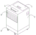
fig. 1 is a schematic diagram of the overall structure of a home artificial intelligence device based on computer internet of things control according to the present invention.
Fig. 2 is a schematic structural diagram of the operation box of the invention.
Fig. 3 is a schematic structural diagram of the filter box of the invention.
Fig. 4 is a schematic view of the filter structure of the present invention.
Fig. 5 is a schematic view of the structure of the stabilizer of the present invention.
FIG. 6 is a schematic diagram of the structure of the cleaner of the present invention.
In the figure: the device comprises a closing cover 1, an operation box 2, universal wheels 3, an exhaust grille 4, a control button 5, a filter box 2a, a heat radiation plate 2b, a dust suction box 2c, an air guide pipe 2d, a purification box 2e, a dust guide pipe 2f, a box body 2g, a sealing cover a1, a cleaner a2, a shell a3, a filter a4, a moving shaft a41, a moving block a42, an installation shaft a43, an installation cavity a44, a stabilizer a45, an installation block a46, a filter plate a47, a positioning plate a48, an assembly block 451, an assembly cavity 452, a rotating block 453, a buckling plate 454, a joint block 455, a cleaning box a21, a brush body a22, a positioning shaft a23, a rotating shaft a24, a fixed shaft a25, an adjusting shaft a26, an adjusting cavity a27 and a pressing plate a 28.
Detailed Description
In order to make the technical means, the original characteristics, the achieved purposes and the effects of the invention easy to understand, the following description and the accompanying drawings further illustrate the preferred embodiments of the invention.
Example one
Referring to fig. 1-5, a household artificial intelligence device based on computer internet of things control structurally comprises a closed cover 1, an operation box 2, a universal wheel 3, an exhaust grille 4 and a control button 5, wherein the closed cover 1 is arranged on the operation box 2, the closed cover 1 is in clearance fit with the operation box 2, the universal wheel 3 is arranged at the bottom of the operation box 2, the operation box 2 is movably connected with the universal wheel 3, the exhaust grille 4 is arranged on the operation box 2, the operation box 2 is embedded with the exhaust grille 4, the control button 5 is arranged on the operation box 2, and the control button 5 is connected with the operation box 2;
The filter a4 is provided with a moving shaft a41, a moving block a42, a mounting shaft a43, a mounting cavity a44, a stabilizer a45, a mounting block a46, a filter plate a47 and a positioning plate a48, the mounting cavity a44 is provided with a positioning plate a48, the positioning plate a48 is movably connected with the mounting cavity a44, both sides of the positioning plate a48 are provided with a moving shaft a41, the moving shaft a41 is connected with the positioning plate a48, the moving shaft a41 is provided with a moving block a42, the moving block a42 is slidably connected with the moving shaft a41, the stabilizer a45 is mounted on the filter plate a47, the filter plate a47 is in clearance fit with the stabilizer a45, both sides of the filter plate a47 are provided with mounting shafts a43, the mounting shafts a43 and the filter plate a47 are movably connected, the mounting block a46 is mounted on the mounting cavity a46 in a snap fit, the mounting cavity a46 is movably connected with the positioning plate a46, the positioning plate a46 is provided with an arc-shaped block 46, the positioning plate a48 is provided with a slide way, the arc-shaped block of the positioning plate a48 is embedded on the slide way through a pulley, two sides of the moving shaft a41 are provided with sliding grooves, two sides of the moving block a42 are provided with sliding shafts, the sliding shafts of the moving block a42 are embedded on the sliding grooves of the moving shaft a41, the moving block a42 is provided with a connecting column, the connecting column of the moving block a42 is provided with a ball connecting block, the ball connecting block of the moving block a42 is filled with rubber wires, the center of the filter plate a47 is provided with a filter grid, the outer edge of the grid of the filter plate a47 is provided with a connecting plate, two sides of the filter plate a47 are provided with arc-shaped positioning notches, the orientations of the positioning notches at two sides of the filter plate a47 are opposite, the positioning notch of the filter plate a47 is matched with the arc-shaped block of the positioning plate a48, the filter plate a47 is provided with an assembling hollow matched with the structure of the moving block a42, the filtering structures are assembled together, so that one-side assembling and disassembling of the filtering structures can be realized.
The square connecting column structure that installation piece a46 was, the cylinder center of installation piece a46 is equipped with the cylinder protruding piece, be equipped with the screw thread strip on the cylinder protruding piece of installation piece a46, the outward flange of installation piece a46 is equipped with the ring connecting block, the ring connecting block and the cylinder protruding piece threaded connection of installation piece a46, be equipped with the fretwork notch identical with installation piece a46 structure on installation axle a43, be equipped with the rotation notch on the installation axle a43, filter a47 passes through the loose axle gomphosis on the rotation notch of installation axle a43, realizes filtration's equipment through buckle structure.
The stabilizer a45 is provided with an assembly block 451, an assembly cavity 452, a rotation block 453, a buckling plate 454 and an attachment block 455, the assembly cavity 452 is internally provided with the attachment block 455, the attachment block 455 is movably connected with the assembly cavity 452, the assembly cavity 452 is provided with the buckling plate 454, the buckling plate 454 is in clearance fit with the assembly cavity 452, the rotation block 453 is arranged at the center of the buckling plate 454, the rotation block 453 is movably buckled with the buckling plate 454, the assembly block 451 is mounted on the rotation block 453, the rotation block 453 is connected with the assembly block 451, the rotation block 453 is movably connected with the buckling plate 454 through a movable shaft, the buckling plate 454 is provided with a circular notch, the rotation block 453 is provided with a handle, the handle of the rotation block 453 is embedded in the circular notch of the buckling plate 454, the assembly block 451 is an L-shaped arc-shaped connecting block, the assembly block 451 is arranged on one side facing the bottom of the cleaning box a21, the mounting cavity a44 is provided with a notch matched with the assembly block 451 in structure, the assembly cavity 452 is arranged on the filter plate a47, and the filter structures at different positions are connected together through an assembly column.
The buckling plate 454 is a cylinder with a long shaft, a connecting body is arranged on the cylinder of the buckling plate 454, the number of the connecting bodies of the buckling plate 454 is the same as that of the filter plates a47 installed on an installation shaft a43, convex blocks are arranged on two sides of the connecting body of the buckling plate 454, an arc-shaped connecting shaft is arranged at one end of the convex block of the buckling plate 454, a circular connecting plate is arranged on the arc-shaped connecting shaft of the buckling plate 454, an arc-shaped groove is arranged on the circular connecting plate of the buckling plate 454, an arc-shaped notch is arranged in the assembly cavity 452, the fitting block 455 is embedded in the notch of the assembly cavity 452, a connecting ball is arranged on the fitting block 455, the connecting ball of the fitting block 455 is movably connected with the assembly cavity 452 through an assembly column, the connecting column of the fitting block 455 is a spiral cylinder made of copper wires, and the structure of the connecting ball of the fitting block 455 is matched with the arc-shaped groove on the circular connecting plate of the buckling plate 454, utilize the connector to install the filtration of different positions on connecting the cylinder, prevent that filtration from overturning again.
The filter plate a47 with different densities is mounted on the mounting shaft a43 through a movable shaft, then the mounting shaft a43 penetrates through the mounting block a46, the filter structure is mounted in the mounting cavity a44, when the filter plate a47 can rotate along the movable shaft between the mounting shaft a43 during mounting, the filter plate a47 inclines at a certain angle, the space during mounting is reduced, the filter structure is conveniently placed in the mounting cavity a44, a power supply is started, the arc-shaped block of the positioning plate a48 extends along the slide way through the sliding wheel, after the filter structure is mounted in the mounting cavity a44, the assembly cavity 452 on the filter plate a47 penetrates through a column with a long shaft, the diameter of the column is smaller than the diameter of the notch of the assembly cavity 452, the connecting plate of the filter plate a47 at another position is pushed, the filter plate a47 is driven to rotate again, the filter plate a47 is perpendicular to the mounting shaft a43, and the notch of the filter plate a47 is attached to the arc-shaped block of the positioning plate a48, thereby realizing the installation and the positioning of the positioning plate a48, the moving block a42 slides along the moving shaft a41, extends out of the positioning plate a48, is buckled into the notch of the filter plate a47 through the connecting structure on the moving block a42 to realize the connection and the fixing of the filter plate a47, then the connector of the buckle plate 454 passes through the notch of the assembly cavity 452 through the convex block on the connector, then the buckle plate 454 is rotated to enable the convex block to be buckled into the arc notch, the sphere structure on the attaching block 455 is buckled into the arc notch of the circular connecting plate of the buckle plate 454, then the block 453 is rotated to further enable the assembly block 451 to be buckled into the installation cavity a44, thereby realizing the connection between the filter plate a47 and the filter plate a47, preventing the filter plate a47 from being overturned again, finally, the sealing cover a1 is installed on the shell a3, the sealing cover a1 is clamped between the circular ring structure and the installation block a46 through the connection between the circular ring structure and the cylinder on the installation block a46, realize the equipment of equipment, and dismantle the filtration and only need remove the buckle, promote filter a47 upset again and move, the location breach orientation of filter a47 is not good, when rotating, just can not have one end and blockked unable rotation by locating plate a48, alright take out the filtration.
Example two
Referring to fig. 1-6, a household artificial intelligence device based on computer internet of things control structurally comprises a closed cover 1, an operation box 2, a universal wheel 3, an exhaust grille 4 and a control button 5, wherein the closed cover 1 is arranged on the operation box 2, the closed cover 1 is in clearance fit with the operation box 2, the universal wheel 3 is arranged at the bottom of the operation box 2, the operation box 2 is movably connected with the universal wheel 3, the exhaust grille 4 is arranged on the operation box 2, the operation box 2 is embedded with the exhaust grille 4, the control button 5 is arranged on the operation box 2, and the control button 5 is connected with the operation box 2;
The filter a4 is provided with a moving shaft a41, a moving block a42, a mounting shaft a43, a mounting cavity a44, a stabilizer a45, a mounting block a46, a filter plate a47 and a positioning plate a48, the mounting cavity a44 is provided with a positioning plate a48, the positioning plate a48 is movably connected with the mounting cavity a44, both sides of the positioning plate a48 are provided with a moving shaft a41, the moving shaft a41 is connected with the positioning plate a48, the moving shaft a41 is provided with a moving block a42, the moving block a42 is slidably connected with the moving shaft a41, the stabilizer a45 is mounted on the filter plate a47, the filter plate a47 is in clearance fit with the stabilizer a45, both sides of the filter plate a47 are provided with mounting shafts a43, the mounting shafts a43 and the filter plate a47 are movably connected, the mounting block a46 is mounted on the mounting cavity a46 in a snap fit, the mounting cavity a46 is movably connected with the positioning plate a46, the positioning plate a46 is provided with an arc-shaped block 46, the positioning plate a48 is provided with a slide way, the arc-shaped block of the positioning plate a48 is embedded on the slide way through a pulley, two sides of the moving shaft a41 are provided with sliding grooves, two sides of the moving block a42 are provided with sliding shafts, the sliding shafts of the moving block a42 are embedded on the sliding grooves of the moving shaft a41, the moving block a42 is provided with a connecting column, the connecting column of the moving block a42 is provided with a ball connecting block, the ball connecting block of the moving block a42 is filled with rubber wires, the center of the filter plate a47 is provided with a filter grid, the outer edge of the grid of the filter plate a47 is provided with a connecting plate, two sides of the filter plate a47 are provided with arc-shaped positioning notches, the orientations of the positioning notches at two sides of the filter plate a47 are opposite, the positioning notch of the filter plate a47 is matched with the arc-shaped block of the positioning plate a48, the filter plate a47 is provided with an assembling hollow matched with the structure of the moving block a42, the filtering structures are assembled together, so that one-side assembling and disassembling of the filtering structures can be realized.
The square connecting column structure that installation piece a46 was, the cylinder center of installation piece a46 is equipped with the cylinder protruding piece, be equipped with the screw thread strip on the cylinder protruding piece of installation piece a46, the outward flange of installation piece a46 is equipped with the ring connecting block, the ring connecting block and the cylinder protruding piece threaded connection of installation piece a46, be equipped with the fretwork notch identical with installation piece a46 structure on installation axle a43, be equipped with the rotation notch on the installation axle a43, filter a47 passes through the loose axle gomphosis on the rotation notch of installation axle a43, realizes filtration's equipment through buckle structure.
The stabilizer a45 is provided with an assembly block 451, an assembly cavity 452, a rotation block 453, a buckling plate 454 and an attachment block 455, the assembly cavity 452 is internally provided with the attachment block 455, the attachment block 455 is movably connected with the assembly cavity 452, the assembly cavity 452 is provided with the buckling plate 454, the buckling plate 454 is in clearance fit with the assembly cavity 452, the rotation block 453 is arranged at the center of the buckling plate 454, the rotation block 453 is movably buckled with the buckling plate 454, the assembly block 451 is mounted on the rotation block 453, the rotation block 453 is connected with the assembly block 451, the rotation block 453 is movably connected with the buckling plate 454 through a movable shaft, the buckling plate 454 is provided with a circular notch, the rotation block 453 is provided with a handle, the handle of the rotation block 453 is embedded in the circular notch of the buckling plate 454, the assembly block 451 is an L-shaped arc-shaped connecting block, the assembly block 451 is arranged on one side facing the bottom of the cleaning box a21, the mounting cavity a44 is provided with a notch matched with the assembly block 451 in structure, the assembly cavity 452 is arranged on the filter plate a47, and the filter structures at different positions are connected together through an assembly column.
The buckling plate 454 is a cylinder with a long shaft, a connecting body is arranged on the cylinder of the buckling plate 454, the number of the connecting bodies of the buckling plate 454 is the same as that of the filter plates a47 installed on an installation shaft a43, convex blocks are arranged on two sides of the connecting body of the buckling plate 454, an arc-shaped connecting shaft is arranged at one end of the convex block of the buckling plate 454, a circular connecting plate is arranged on the arc-shaped connecting shaft of the buckling plate 454, an arc-shaped groove is arranged on the circular connecting plate of the buckling plate 454, an arc-shaped notch is arranged in the assembly cavity 452, the fitting block 455 is embedded in the notch of the assembly cavity 452, a connecting ball is arranged on the fitting block 455, the connecting ball of the fitting block 455 is movably connected with the assembly cavity 452 through an assembly column, the connecting column of the fitting block 455 is a spiral cylinder made of copper wires, and the structure of the connecting ball of the fitting block 455 is matched with the arc-shaped groove on the circular connecting plate of the buckling plate 454, utilize the connector to install the filtration of different positions on connecting the cylinder, prevent that filtration from overturning again.
The cleaner a is provided with a cleaning box a, a brush body a, a positioning shaft a, a rotating shaft a, a fixed shaft a, an adjusting cavity a and a pressing plate a, the pressing plate a is arranged at the center of the cleaning box a and is in clearance fit with the cleaning box a, the rotating shaft a is arranged on the fixed shaft a and is in clearance fit with the rotating shaft a, the adjusting cavity a is arranged at the outer edge of the rotating shaft a and is connected with the rotating shaft a, the adjusting shaft a is arranged in the adjusting cavity a and is movably connected with the adjusting cavity a, the brush body a is arranged on the adjusting shaft a, the adjusting shaft a is movably clamped with the brush body a, the positioning shaft a is arranged on the adjusting cavity a and is in clearance fit with the positioning shaft a, the positioning shaft a is a cylinder with a long shaft, thread strips are arranged on two sides of the cylinder of the positioning shaft a, the two sides of the positioning shaft a23 are provided with circular ring connecting shafts, the circular ring connecting shaft of the positioning shaft a23 is in threaded connection with the cylinder, the adjusting shaft a26 is provided with a sliding shaft, the connecting block at the other end of the adjusting shaft a26 is provided with a connecting groove, the brush body a22 is provided with a connecting block matched with the connecting groove structure of the adjusting shaft a26, the connecting block of the adjusting shaft a26 is provided with a threaded hole, the sliding shafts of the positioning shaft a23 and the adjusting shaft a26 are both provided with hollowed-out holes, and impurities falling off inside the filtering assembly structure can be further cleaned through a cleaning structure after the filtering structure is disassembled by the equipment.
Cleaning box a 21's central point puts and is equipped with the connection chamber, be equipped with the screw thread strip on the wall body in cleaning box a21 connection chamber, fixed axle a25 is for connecting the cylinder, fixed axle a25 is equipped with the screw thread cylinder towards one side of cleaning box a21, the inside spiral cylinder of being equipped with by the copper wire of connection chamber of cleaning box a21, the spiral cylinder other end of cleaning box a21 is connected with pressing plate a28, be equipped with the protruding axle of ring on fixed axle a 25's the cylinder, be equipped with the connection notch on axis of rotation a24, axis of rotation a24 is connected through the circular arc protruding axle of connecting notch with fixed axle a25, pressing plate a28 is circular plate, pressing plate a 28's circular plate diameter is identical with cleaning box a 21's the connection chamber diameter, realizes the installation of cleaning structure through connection structure.
A cleaning device a2 is installed on the basis of the first embodiment, a protruding block of a brush body a22 is buckled into an adjusting shaft a26 and is connected together through threads, the adjusting shaft a26 slides along an adjusting cavity a27, the diameter of a rotating structure can be adjusted according to the diameter of a cavity, after the moving position of an adjusting shaft a26 is adjusted, a positioning shaft a23 penetrates through a hollow opening of an adjusting shaft a26 and an adjusting cavity a27 and is connected to two sides of the positioning shaft a23 through a circular ring structure to achieve sliding positioning, when the pressing plate a28 is not installed, the pressing plate a28 can block a notch of a21 to prevent separated impurities from falling into the notch of the cleaning box a21, then the fixing shaft a25 presses the pressing plate a28 to rotate the fixing shaft a25, so that a threaded column on the fixing shaft a25 is connected with a wall body of a connecting cavity at the center of the cleaning box a21, the rotating shaft a21 can be taken out, the cleaning box a21 can be rotated, 68628 a 599 a rotates along the fixing shaft 599 a, the brush body a22 is used for cleaning the wall body of the installation cavity a44, and further cleaning impurities in the box body 2 g.
While there have been shown and described what are at present considered the fundamental principles of the invention, the essential features and advantages thereof, it will be understood by those skilled in the art that the present invention is not limited by the embodiments described above, which are merely illustrative of the principles of the invention, but rather, is capable of numerous changes and modifications in various forms without departing from the spirit or essential characteristics thereof, and it is intended that the invention be limited not by the foregoing descriptions, but rather by the appended claims and their equivalents.
Furthermore, it should be understood that although the present description refers to embodiments, not every embodiment may contain only a single embodiment, and such description is for clarity only, and those skilled in the art should integrate the description, and the embodiments may be combined as appropriate to form other embodiments understood by those skilled in the art.
Claims (8)
1. A family artificial intelligence equipment based on computer internet of things control, characterized by: the structure of the air-conditioning device comprises a closed cover (1), an operation box (2), universal wheels (3), an exhaust grille (4) and a control button (5), wherein the closed cover (1) is arranged on the operation box (2), the operation box (2) is movably connected with the universal wheels (3), the exhaust grille (4) is arranged on the operation box (2), and the control button (5) is arranged on the operation box (2);
operation box (2) are equipped with rose box (2 a), heating panel (2 b), suction box (2 c), air duct (2 d), purifying box (2 e), lead dirt pipe (2 f), box (2 g), rose box (2 a) and box (2 g) activity block, it installs on suction box (2 c) to lead dirt pipe (2 f), box (2 g) are connected with purifying box (2 e), establish on rose box (2 a) air duct (2 d), box (2 g) and heating panel (2 b) clearance fit.
2. The household artificial intelligence device based on the computer internet of things control as claimed in claim 1, wherein: the filter box (2 a) is provided with a sealing cover (a 1), a cleaner (a 2), a shell (a 3) and a filter (a 4), wherein the sealing cover (a 1) is embedded with the shell (a 3), the cleaner (a 2) is arranged inside the shell (a 3), and the filter (a 4) is embedded with the shell (a 3).
3. The household artificial intelligence device based on the computer internet of things control as claimed in claim 2, wherein: the filter (a 4) is provided with a moving shaft (a 41), a moving block (a 42), a mounting shaft (a 43), a mounting cavity (a 44), a stabilizer (a 45), a mounting block (a 46), a filter plate (a 47) and a positioning plate (a 48), the mounting cavity (a 44) is provided with the positioning plate (a 48), the moving shaft (a 41) is connected with the positioning plate (a 48), the moving shaft (a 41) is provided with the moving block (a 42), the filter plate (a 47) is in clearance fit with the stabilizer (a 45), the two sides of the filter plate (a 47) are provided with mounting shafts (a 43), and the mounting cavity (a 44) is movably connected with the mounting block (a 46).
4. The household artificial intelligence device based on the computer internet of things control as claimed in claim 3, wherein: the mounting block (a 46) is a square connecting column structure, and a cylindrical protruding block is arranged at the center of the column body of the mounting block (a 46).
5. The household artificial intelligence device based on the computer internet of things control as claimed in claim 3, wherein: the stabilizer (a 45) is provided with an assembly block (451), an assembly cavity (452), a rotating block (453), a buckle plate (454) and an attachment block (455), the attachment block (455) is arranged inside the assembly cavity (452), the buckle plate (454) is in clearance fit with the assembly cavity (452), the rotating block (453) is arranged at the center of the buckle plate (454), the rotating block (453) is connected with the assembly block (451), and the rotating block (453) is movably connected with the buckle plate (454) through a movable shaft.
6. The household artificial intelligence device based on the computer internet of things control as claimed in claim 5, wherein: the buckling plate (454) is a long-axis cylinder, and a connecting body is arranged on the cylinder of the buckling plate (454).
7. The household artificial intelligence device based on the computer internet of things control as claimed in claim 2, wherein: the cleaner (a 2) is provided with a cleaning box (a 21), a brush body (a 22), a positioning shaft (a 23), a rotating shaft (a 24), a fixed shaft (a 25), an adjusting shaft (a 26), an adjusting cavity (a 27) and a pressing plate (a 28), the pressing plate (a 28) is arranged at the center of the cleaning box (a 21), the fixed shaft (a 25) is in clearance fit with the rotating shaft (a 24), the adjusting cavity (a 27) is arranged at the outer edge of the rotating shaft (a 24), the adjusting shaft (a 26) is movably connected with the adjusting cavity (a 27), the brush body (a 22) is installed on the adjusting shaft (a 26), and the adjusting cavity (a 27) is in clearance fit with the positioning shaft (a 23).
8. The household artificial intelligence device based on the computer internet of things control as claimed in claim 7, wherein: the central position of clearance case (a 21) is equipped with the connection chamber, be equipped with the screw thread strip on the wall body that clearance case (a 21) connects the chamber.
Priority Applications (1)
| Application Number | Priority Date | Filing Date | Title |
|---|---|---|---|
| CN202110697589.5A CN113566370A (en) | 2021-06-23 | 2021-06-23 | Household artificial intelligence equipment based on computer internet of things control |
Applications Claiming Priority (1)
| Application Number | Priority Date | Filing Date | Title |
|---|---|---|---|
| CN202110697589.5A CN113566370A (en) | 2021-06-23 | 2021-06-23 | Household artificial intelligence equipment based on computer internet of things control |
Publications (1)
| Publication Number | Publication Date |
|---|---|
| CN113566370A true CN113566370A (en) | 2021-10-29 |
Family
ID=78162574
Family Applications (1)
| Application Number | Title | Priority Date | Filing Date |
|---|---|---|---|
| CN202110697589.5A Pending CN113566370A (en) | 2021-06-23 | 2021-06-23 | Household artificial intelligence equipment based on computer internet of things control |
Country Status (1)
| Country | Link |
|---|---|
| CN (1) | CN113566370A (en) |
Cited By (2)
| Publication number | Priority date | Publication date | Assignee | Title |
|---|---|---|---|---|
| CN114322505A (en) * | 2021-12-27 | 2022-04-12 | 西南医科大学附属医院 | Disinfection drying device for surgical knife |
| CN115067367A (en) * | 2022-05-30 | 2022-09-20 | 蔡鼎 | Robot for processing egg food |
Citations (5)
| Publication number | Priority date | Publication date | Assignee | Title |
|---|---|---|---|---|
| US20030192432A1 (en) * | 2002-04-11 | 2003-10-16 | Deseret Laboratories, Inc. | Filter apparatus |
| CN208457976U (en) * | 2018-05-11 | 2019-02-01 | 山东格瑞德集团有限公司 | A kind of environment-friendly type burning purification furnace |
| CN211097921U (en) * | 2019-11-04 | 2020-07-28 | 江苏天雅环保科技有限公司 | Ceramic filter element with conical ring mounted at interface |
| CN211716790U (en) * | 2019-12-21 | 2020-10-20 | 广东国基实业有限公司 | Sound-proof building energy-saving ventilation device |
| CN112696818A (en) * | 2021-01-12 | 2021-04-23 | 四川长虹空调有限公司 | Air conditioner filter screen assembly |
-
2021
- 2021-06-23 CN CN202110697589.5A patent/CN113566370A/en active Pending
Patent Citations (5)
| Publication number | Priority date | Publication date | Assignee | Title |
|---|---|---|---|---|
| US20030192432A1 (en) * | 2002-04-11 | 2003-10-16 | Deseret Laboratories, Inc. | Filter apparatus |
| CN208457976U (en) * | 2018-05-11 | 2019-02-01 | 山东格瑞德集团有限公司 | A kind of environment-friendly type burning purification furnace |
| CN211097921U (en) * | 2019-11-04 | 2020-07-28 | 江苏天雅环保科技有限公司 | Ceramic filter element with conical ring mounted at interface |
| CN211716790U (en) * | 2019-12-21 | 2020-10-20 | 广东国基实业有限公司 | Sound-proof building energy-saving ventilation device |
| CN112696818A (en) * | 2021-01-12 | 2021-04-23 | 四川长虹空调有限公司 | Air conditioner filter screen assembly |
Cited By (3)
| Publication number | Priority date | Publication date | Assignee | Title |
|---|---|---|---|---|
| CN114322505A (en) * | 2021-12-27 | 2022-04-12 | 西南医科大学附属医院 | Disinfection drying device for surgical knife |
| CN115067367A (en) * | 2022-05-30 | 2022-09-20 | 蔡鼎 | Robot for processing egg food |
| CN115067367B (en) * | 2022-05-30 | 2023-07-07 | 昆明冬冬食品有限公司 | Robot for processing egg food |
Similar Documents
| Publication | Publication Date | Title |
|---|---|---|
| CN207688241U (en) | Air processor and floor air conditioner with it | |
| AU2019207107B2 (en) | Filter structure capable of removing dust | |
| US11433345B2 (en) | Air-conditioning device having dust removing function | |
| CN113566370A (en) | Household artificial intelligence equipment based on computer internet of things control | |
| EP3485955B1 (en) | Air purifier | |
| AU2020439929B2 (en) | Fresh air module and air conditioner | |
| CN106377210A (en) | Moveable robot cleaner | |
| CN111306631A (en) | Fresh air module and air conditioner | |
| CN207422376U (en) | Air processor, air conditioner indoor unit, air-conditioner outdoor unit and air conditioner | |
| CN215113141U (en) | Air purifier | |
| CN209953461U (en) | Be used for zinc oxide production to use dust collection device | |
| CN210107666U (en) | Indoor ventilation pipeline of building | |
| CN207146567U (en) | Air treatment module and air conditioner | |
| CN219120692U (en) | Multiple purifying and filtering circulation fan | |
| CN201246820Y (en) | Air conditioner | |
| CN217849553U (en) | Camera head | |
| CN214038651U (en) | Novel detachable volute for indoor unit of air conditioner | |
| CN217797937U (en) | Pig is with concentrated feed processing dust collector | |
| CN216647522U (en) | Smoke sensor with filtering capability | |
| CN211060320U (en) | New fan | |
| CN210206184U (en) | Air purifier capable of cleaning filter screen | |
| CN211854209U (en) | Fresh air module and air conditioner | |
| CN216467267U (en) | Energy-conserving air conditioner filter screen of [ electric ] motor coach | |
| CN215490192U (en) | Wall-hanging new trend sterilizing machine convenient to installation | |
| CN210980155U (en) | Indoor self-propelled air purifier |
Legal Events
| Date | Code | Title | Description |
|---|---|---|---|
| PB01 | Publication | ||
| PB01 | Publication | ||
| SE01 | Entry into force of request for substantive examination | ||
| SE01 | Entry into force of request for substantive examination | ||
| RJ01 | Rejection of invention patent application after publication |
Application publication date: 20211029 |