US1856447A - Buckle - Google Patents
Buckle Download PDFInfo
- Publication number
- US1856447A US1856447A US439915A US43991530A US1856447A US 1856447 A US1856447 A US 1856447A US 439915 A US439915 A US 439915A US 43991530 A US43991530 A US 43991530A US 1856447 A US1856447 A US 1856447A
- Authority
- US
- United States
- Prior art keywords
- belt
- shaft
- tongues
- buckle
- rim
- Prior art date
- Legal status (The legal status is an assumption and is not a legal conclusion. Google has not performed a legal analysis and makes no representation as to the accuracy of the status listed.)
- Expired - Lifetime
Links
- 210000002105 tongue Anatomy 0.000 description 21
- 239000002184 metal Substances 0.000 description 5
- 239000010985 leather Substances 0.000 description 3
- 244000182067 Fraxinus ornus Species 0.000 description 2
- DOSMHBDKKKMIEF-UHFFFAOYSA-N 2-[3-(diethylamino)-6-diethylazaniumylidenexanthen-9-yl]-5-[3-[3-[4-(1-methylindol-3-yl)-2,5-dioxopyrrol-3-yl]indol-1-yl]propylsulfamoyl]benzenesulfonate Chemical compound C1=CC(=[N+](CC)CC)C=C2OC3=CC(N(CC)CC)=CC=C3C(C=3C(=CC(=CC=3)S(=O)(=O)NCCCN3C4=CC=CC=C4C(C=4C(NC(=O)C=4C=4C5=CC=CC=C5N(C)C=4)=O)=C3)S([O-])(=O)=O)=C21 DOSMHBDKKKMIEF-UHFFFAOYSA-N 0.000 description 1
- 238000005452 bending Methods 0.000 description 1
- 238000009958 sewing Methods 0.000 description 1
Images
Classifications
-
- A—HUMAN NECESSITIES
- A44—HABERDASHERY; JEWELLERY
- A44B—BUTTONS, PINS, BUCKLES, SLIDE FASTENERS, OR THE LIKE
- A44B11/00—Buckles; Similar fasteners for interconnecting straps or the like, e.g. for safety belts
- A44B11/20—Buckles; Similar fasteners for interconnecting straps or the like, e.g. for safety belts engaging holes or the like in strap
- A44B11/24—Buckle with movable prong
-
- Y—GENERAL TAGGING OF NEW TECHNOLOGICAL DEVELOPMENTS; GENERAL TAGGING OF CROSS-SECTIONAL TECHNOLOGIES SPANNING OVER SEVERAL SECTIONS OF THE IPC; TECHNICAL SUBJECTS COVERED BY FORMER USPC CROSS-REFERENCE ART COLLECTIONS [XRACs] AND DIGESTS
- Y10—TECHNICAL SUBJECTS COVERED BY FORMER USPC
- Y10T—TECHNICAL SUBJECTS COVERED BY FORMER US CLASSIFICATION
- Y10T24/00—Buckles, buttons, clasps, etc.
- Y10T24/34—Combined diverse multipart fasteners
- Y10T24/3401—Buckle
- Y10T24/3403—Buckle and buckles
- Y10T24/3408—Buckle and buckles having disconnect structure
Definitions
- This invention relates te improvements in i Sam Brown belts, and has for its object to provide an improved means of attaching two ends of a belt so that they may be easily disconnected so that the belt may be removed from the body of the wearer.
- the leather is not continuously exed by buckling and unbuckling. When using my invention this materially lengthens the life of the belt.
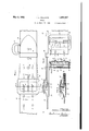
- Figure l is a plan view 0f a section of a belt, showing the buckle uniting two ends of the belt.
- Figure 2 is a side view of the part of the belt shown in Figure l.
- Figure 3 is a bottom plan view of the belt and buckle shown in Figure 1.
- Figure 4 is a section on the line 4 4 of Y Figure 1.
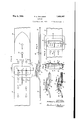
- Figure 8 is a bottom plan view of the form shown in Figure 6.
- Figure 9 is a section on the line 9 9 of Figure 6.
- Figure l0 is a section on the line lO-lO of 55 Figure 6.
- Figure l1 is a section on the line 11*11 of Figure 6.
- This invention relates to improvements in,W buckles for use on army belts known as the" 30 Sam Brown type of belts.
- the rim of the buckle is indicated by the numeral l and has extending backwardly therefrom, at each side, a. projection 2 whichM has therein a hole 8.
- a shaft 4 Extending between the 65 background projections is a shaft 4, the ends of which engage the holes 3 so that the shaft may easily rotate on the rim of the buckle.
- tongues 5 Extending upwardly from the shaft and at... right angles thereto are tongues 5.
- the tongues unite with the shaft there is formed by means of a bar 6a between the tongues a slot 6, for a purpose hereinafter to be described.
- there A are shown two tongues, each of which has beyond the bar 6a a. prong 7 extending therefrom at right angles to the part of the tongue adjacent the shaft and perpendicular to a plane passing through the shaft and the parts of the tongues adjacent thereto. '8o
- the numeral 8 is used to designate a. strip of metal which has extending therefrom, as shown in Figures 2, 3, 4 and 5, a hook 9. This hook is to engage the shaft 4, through the slot 6, for the purpose of joining the strip 8 and the rim 1.
- the metal strip 8 On one end l2 of the belt member there is attached the metal strip 8, as shown in Figure 2.
- the metal strip On one end l2 of the belt member there is attached the metal strip 8, as shown in Figure 2.
- For the purpose of accommodating the hooks on this strip there is provided one or more slits in the leather.
- the hook prongs are inserted through the slits, after which the leather is bent back and properly attached to the main body of the belt by sewing, brads or otherwise.
- the other end l0 of the belt called the tongue end of the 95 belt, is adapted to receive the buckle, composed'of the rim and the tongues. This end of the belt is slipped in between the rim and the shaft. After it has been thus inserted the tongues arev inserted into and through holes 11, and pressed down to the position shown in Figure 1. In this position the parts 7 of the tongues rest upon one side of the rim,
- a flap 13 beneath the belt for protecting the clothesk of the wearer from the buckle and the parts associated therewith.
- This flap is attached to the belt in the same lmanner that 'the metal strip 8 is attached, andmay be attached thereto atV the same time and by the same means.
- 17 is the usualring found in belts of this type, to which one end of a shoulder strap is attached.
- a buckle an outer rim, a shaft pivoted at its ends tosaid rim, a pair of tongues on said shaft spaced from each other and the ends of the shaft, and means between the tongues to form with the shaft a hook slot and to support a belt engaged by the tongues so there will be a space between thebelt and the shaft on each side of the tongues, whereby a double-prongedhook may engage the shaft between the tongues and the rim.
- the belt may be easily attachedv to the body of the wearer bymerely bringing the hook in engagement with the shaft.
- the hook is suiiiciently long and deepthat it will not become disconnected by ordinary usage.
- the belt may be easily removed, easily placed inposition on the wearer, and may be as easibar between the tongues and spaced from the Y shaft associated with the shaft forrkeeping a belt on the hooks within the rim from en-
Landscapes
- Buckles (AREA)
Description
May 3, 1932.
F. L. WILLIAMS,
BUCKLE 2 Sheets-Sheet Filed March 29, 1930 JNVENTOR Foreessr 1 WILL/fins.
-f- JMW' @Il t A TT ORNE Y May 3, 1932. F. l.. WILLIAMS BUCKLE Filed March 29, 1930 2 Sheets-Sheet 2 INVENTOR FOBEEST L. WILL/HNS- A TT ORNE Y Patented May 3, 1932 UNITED STATES PATENT OFFICE l-E'ORRIE'KS'I L. WILLIAMS, OF PORTSMOUTH, OHIO, .ASSIGNOR TO WILLIAMS lvlIAIhTUlAC-V TUBING COMPANY, OF PORTSMOUTH, OHIO, A CORPORATION 0F OHIO BUCKLE Application led March 29, 1930. Serial No. 439,915.
This invention relates te improvements in i Sam Brown belts, and has for its object to provide an improved means of attaching two ends of a belt so that they may be easily disconnected so that the belt may be removed from the body of the wearer.
It is particularly the object of this invention to provide a belt in which there is a rim member removably and adjustably attached to one end of a belt, while to the other end of the belt there is attached a hook for engaging a part of the rim for holding the belt in position on the wearer.
Itis also an object of this invention to provide in connection with the rim of a belt buckle a pivoted shaft having one or more tongues thereon to engage holes in one end of a belt, and provide means -on the shaft by which the other end of the belt may be held in engagement with the first end by means of a hook.
It is also an object of this invention to make the shaft in such form and shape that either a single prong hook or a double prong hook may be used for the purpose of uniting the two ends of the belt for wearing purposes.
These and other advantages will appear from the description taken in connection with the drawings. The leather is not continuously exed by buckling and unbuckling. When using my invention this materially lengthens the life of the belt.
Referring to the drawings:
Figure l is a plan view 0f a section of a belt, showing the buckle uniting two ends of the belt.
Figure 2 is a side view of the part of the belt shown in Figure l.
Figure 3 is a bottom plan view of the belt and buckle shown in Figure 1.
Figure 4 is a section on the line 4 4 of Y Figure 1.
lso
Figure 8 is a bottom plan view of the form shown in Figure 6.
Figure 9 is a section on the line 9 9 of Figure 6. x
Figure l0 is a section on the line lO-lO of 55 Figure 6.
Figure l1 is a section on the line 11*11 of Figure 6.
This invention relates to improvements in,W buckles for use on army belts known as the" 30 Sam Brown type of belts.
The rim of the buckle is indicated by the numeral l and has extending backwardly therefrom, at each side, a. projection 2 whichM has therein a hole 8. Extending between the 65 background projections is a shaft 4, the ends of which engage the holes 3 so that the shaft may easily rotate on the rim of the buckle. Extending upwardly from the shaft and at... right angles thereto are tongues 5. At the "10 point where the tongues unite with the shaft there is formed by means of a bar 6a between the tongues a slot 6, for a purpose hereinafter to be described. In the present instance there A are shown two tongues, each of which has beyond the bar 6a a. prong 7 extending therefrom at right angles to the part of the tongue adjacent the shaft and perpendicular to a plane passing through the shaft and the parts of the tongues adjacent thereto. '8o
The numeral 8 is used to designate a. strip of metal which has extending therefrom, as shown in Figures 2, 3, 4 and 5, a hook 9. This hook is to engage the shaft 4, through the slot 6, for the purpose of joining the strip 8 and the rim 1. On one end l2 of the belt member there is attached the metal strip 8, as shown in Figure 2. For the purpose of accommodating the hooks on this strip there is provided one or more slits in the leather.
The hook prongs are inserted through the slits, after which the leather is bent back and properly attached to the main body of the belt by sewing, brads or otherwise. The other end l0 of the belt, called the tongue end of the 95 belt, is adapted to receive the buckle, composed'of the rim and the tongues. This end of the belt is slipped in between the rim and the shaft. After it has been thus inserted the tongues arev inserted into and through holes 11, and pressed down to the position shown in Figure 1. In this position the parts 7 of the tongues rest upon one side of the rim,
while the part of the tongue adjacent the shaft fits in vthe holes V11 and holds the belt in the position shown in Figure 1.
There is also provided a flap 13 beneath the belt for protecting the clothesk of the wearer from the buckle and the parts associated therewith. This flap is attached to the belt in the same lmanner that 'the metal strip 8 is attached, andmay be attached thereto atV the same time and by the same means. There is also provided in the hook end 12 of the belt Y a stud 14 adapted to engage' a'suitable hole Vo-r slit 15 in the tongue end 10 of the belt.
There may be also provided a loop 16 under which the extreme end of the belt may be held to keep it from bending up or getting 20 out of place and shape. 17 is the usualring found in belts of this type, to which one end of a shoulder strap is attached.
gaging the shaft and in spaced relation there'- to. l
2. In a buckle, an outer rim, a shaft pivoted at its ends tosaid rim, a pair of tongues on said shaft spaced from each other and the ends of the shaft, and means between the tongues to form with the shaft a hook slot and to support a belt engaged by the tongues so there will be a space between thebelt and the shaft on each side of the tongues, whereby a double-prongedhook may engage the shaft between the tongues and the rim.
VIn testimony whereof, I affix my signature.
y FORREST L. WILLIAMS.
In the form ofbelt shown in Figures to 5 there isused only one hook on the metal strip 8. In the form shown in Figures 6 to 11 there are two hooks. The parts ofv the belt are identical with the exception that in this form the metal strip 8 has extending therefrom` two hook members, the hook prongs 9'.. Instead ofthese prongs engaging in the slot 6,
as in the other form, they engage the shaftl between ythe tongues and the backward projections2 on the rim. In other words, these hooks engage the shaft adjacent each side of the rim so that in this form of belt buckle the ends of the belt are held in more nearly ,perfect alignment with each other so that they 'cannot become out of line, there being two separate and remote bearing points, one adj a- Y cent each side of the belt buckle rim.
After the buckle has been properly adjust- Ved by means of the tongues on one end of the belt, the belt may be easily attachedv to the body of the wearer bymerely bringing the hook in engagement with the shaft. The hook is suiiiciently long and deepthat it will not become disconnected by ordinary usage. The belt may be easily removed, easily placed inposition on the wearer, and may be as easibar between the tongues and spaced from the Y shaft associated with the shaft forrkeeping a belt on the hooks within the rim from en-
Priority Applications (1)
| Application Number | Priority Date | Filing Date | Title |
|---|---|---|---|
| US439915A US1856447A (en) | 1930-03-29 | 1930-03-29 | Buckle |
Applications Claiming Priority (1)
| Application Number | Priority Date | Filing Date | Title |
|---|---|---|---|
| US439915A US1856447A (en) | 1930-03-29 | 1930-03-29 | Buckle |
Publications (1)
| Publication Number | Publication Date |
|---|---|
| US1856447A true US1856447A (en) | 1932-05-03 |
Family
ID=23746663
Family Applications (1)
| Application Number | Title | Priority Date | Filing Date |
|---|---|---|---|
| US439915A Expired - Lifetime US1856447A (en) | 1930-03-29 | 1930-03-29 | Buckle |
Country Status (1)
| Country | Link |
|---|---|
| US (1) | US1856447A (en) |
Cited By (2)
| Publication number | Priority date | Publication date | Assignee | Title |
|---|---|---|---|---|
| US2427797A (en) * | 1944-04-10 | 1947-09-23 | Francis J Mack | Buckle and strap |
| US10702034B2 (en) * | 2016-06-03 | 2020-07-07 | Coral Chung | Convertible strap handbag |
-
1930
- 1930-03-29 US US439915A patent/US1856447A/en not_active Expired - Lifetime
Cited By (3)
| Publication number | Priority date | Publication date | Assignee | Title |
|---|---|---|---|---|
| US2427797A (en) * | 1944-04-10 | 1947-09-23 | Francis J Mack | Buckle and strap |
| US10702034B2 (en) * | 2016-06-03 | 2020-07-07 | Coral Chung | Convertible strap handbag |
| USD902598S1 (en) | 2016-06-03 | 2020-11-24 | Coral Chung | Convertible strap handbag rear portion |
Similar Documents
| Publication | Publication Date | Title |
|---|---|---|
| US2051591A (en) | Clasp for string jewelry | |
| US1996276A (en) | Wrist watch strap | |
| US1754200A (en) | Assianob | |
| US1856447A (en) | Buckle | |
| US1497585A (en) | Cast-off for garters | |
| US1847182A (en) | Belt | |
| US2191210A (en) | Buckle | |
| US2397651A (en) | Means for securing indentification tags | |
| US1559291A (en) | Belt | |
| US1570625A (en) | Garment clasp and method of making same | |
| US2471694A (en) | Adjustable metallic wrist band | |
| US849677A (en) | Combined trousers-clasp and belt-holder. | |
| US1397673A (en) | Belt-buckle | |
| US133904A (en) | Improvement in harness-buckles | |
| US1772886A (en) | Buckle | |
| US1600279A (en) | Belt | |
| US1732267A (en) | Safety clasp | |
| US1469859A (en) | Buckle | |
| US2865074A (en) | Buckle for reversible belts | |
| US1698530A (en) | of cincinnati | |
| US2180786A (en) | Buckle | |
| US460304A (en) | Clasp | |
| US1826231A (en) | Buckle | |
| US1866355A (en) | Slide fastener socket member | |
| US1200518A (en) | Brassiere-buckle. |