US1854736A - Tool for use in assembling universal joints - Google Patents
Tool for use in assembling universal joints Download PDFInfo
- Publication number
- US1854736A US1854736A US378638A US37863829A US1854736A US 1854736 A US1854736 A US 1854736A US 378638 A US378638 A US 378638A US 37863829 A US37863829 A US 37863829A US 1854736 A US1854736 A US 1854736A
- Authority
- US
- United States
- Prior art keywords
- handle member
- tool
- handle
- plane
- bearing cap
- Prior art date
- Legal status (The legal status is an assumption and is not a legal conclusion. Google has not performed a legal analysis and makes no representation as to the accuracy of the status listed.)
- Expired - Lifetime
Links
- 238000010276 construction Methods 0.000 description 1
- 230000037431 insertion Effects 0.000 description 1
- 238000003780 insertion Methods 0.000 description 1
- 239000002184 metal Substances 0.000 description 1
Images
Classifications
-
- B—PERFORMING OPERATIONS; TRANSPORTING
- B25—HAND TOOLS; PORTABLE POWER-DRIVEN TOOLS; MANIPULATORS
- B25B—TOOLS OR BENCH DEVICES NOT OTHERWISE PROVIDED FOR, FOR FASTENING, CONNECTING, DISENGAGING OR HOLDING
- B25B27/00—Hand tools, specially adapted for fitting together or separating parts or objects whether or not involving some deformation, not otherwise provided for
-
- Y—GENERAL TAGGING OF NEW TECHNOLOGICAL DEVELOPMENTS; GENERAL TAGGING OF CROSS-SECTIONAL TECHNOLOGIES SPANNING OVER SEVERAL SECTIONS OF THE IPC; TECHNICAL SUBJECTS COVERED BY FORMER USPC CROSS-REFERENCE ART COLLECTIONS [XRACs] AND DIGESTS
- Y10—TECHNICAL SUBJECTS COVERED BY FORMER USPC
- Y10T—TECHNICAL SUBJECTS COVERED BY FORMER US CLASSIFICATION
- Y10T29/00—Metal working
- Y10T29/53—Means to assemble or disassemble
- Y10T29/53909—Means comprising hand manipulatable tool
Definitions
- This invention relates to a tool to be used in assembling universal joints.
- universal joints are employed in which one of the joint knuckles 5 with one of the bearing caps is incased in one-half of the joint casing.
- the clearance between the edge of the bearing cap and the casing is exceedinglysmall sothat it is impossible to insert the hand or fingers. This makes it exceedingly difficult and often impossible to hold the bearing cap in position while placing the other knuckle joint and remaining bearing cap in place.
- the principal object of this invention is toprovide a tool which can be effectively used for holding the universal joint bearing cap in position while the remaining cap is being assembled.
- “Another object of this invention is to provide a tool of this nature which will be locked in position so that both hands may be used for assembling the remaining half of the universal joint.
- Fig. 1 is a perspective view of the improved tool in the partially closed position.
- Fig. 2 is a plan view of the toolin the open position. 7
- Fig. 3 illustrates the tool in use upon a typical universal joint assembly.
- the invention comprises a plier-like tool consisting of a first handle member 10 and a second handle member 11 secured together upon a pivot pin 12.
- One extremity of the first handle member 10 is bifurcated so as to form two forwardly projecting furca tions 13.
- the furcations 13 are bent downwardly for a portion of their length, as shown at 14 and thence extend forwardly substantially parallel to the plane of the handle 10.
- furcations13 are relatively thin so that they can be inserted in the space between the hearing cap and the casing of a universal joint.
- the second'handle member 11 is formed with an eccentric cam surface 15 at tremity, and with a notch 16 formed immediately behind the cam surface 15. The other extremity of the second handle member 11 opening the tool when the two handles are in alignment with each other.
- the first handle member 10 is provided with a stop 18 which may be formed by indenting a portion'of the metal thereof.
- the stop 18 serves to limit the amount of opening of the tool, as illustrated in Fig. 2. When in the fully opened position the notch 16 aligns with the n'otchbetween the furcations 13015 the first handle member 10.
- Fig. 3 One-half of a typical universal joint is illustrated in Fig. 3.
- half of the joint casing is illustrated at 19; half of the joint bearing, herein designated as a bearing cap, at 20; and one of the joint knuckles at 21.
- the bearing cap 20 is provided with sockets 22 for receiving the journal extremities 23 of the joint knuckles and with studs 25 for securing the remaining bearing cap (not shown) in place over the assembled knuckles.
- the furcations 13 are inserted between the casing 19 and the edge of the bearing cap 20.
- the handle members are then forcedtoward the casing 19 to cause the fur-cations 13 to engage the back of the bearing cap 20 to bring it against the back side of the journals 23.
- the lower handle member 11 is closed causing the cam surface 15 to engage the ex tremity of a journal 23.
- This firmly locks the tool in the position illustrated in Fig. 3, so that it can bereleased and the mechanic can employ both of his hands to place the other knuckle and the remaining half of the bearing in position.
- the surfaces of the its exis turned, as shown at 17 to facilitate furcations 13 are slightly inclined toward the axis of the tool as shown in Figs. 1 and 2 to conform to the curvature of the back of the bearing cap 20.
- the turned extremity 17 forms a very handy tool for taking up. the bushing screw in automobile drag links.
- the handle member is useful as a separate unit and can be employed to carry out the above operation without the second handle member 11 but if used alone it must be held in place by the operator while the universal joint is being assembled.
- a tool for assemblingv universal joints of the type having a casing and a joint knuckle bearing cap within said casing comprising: a first handle member; forked extremities formed on said handle member and arranged for insertion.
- An assembling tool comprising: a relatively fiat first handle member; a bifurcated extremity on said handle member. each of the furcations of which extends in the plane of said handle member for a portion of its length, substantiallyat right angles to" the plane of said handle member for another portion of its length, thence forwardly substantially parallel to the plane of said handle for the remaining portion of its length; a second handle member pivoted on said first handle member so as to swing in a plane parallel with the surface of said first handle member; and a projecting surface on said second handle member adapted toswing into said bifurcated extremity as said two handle members are'brought into alignment so as to reduce the depth of the notch between said furca- 'tions.
- An assembling tool comprising: a relatively flat first handle member; a bifurcated extremity on said handle, member, each of the furcations of which extends in the plane of said handle member for a portion of its length, substantially at right angles to the plane of said handle member for another portion. of its length, thence forwardly substantially parallel to. the plane of said handle for the remaining portion of its length; a second handle member pivoted on said first handle member; and a cam surface on said second a handle member adapted to gradually decrease the depth of the notch between said furcations as said handle members are brought into alignment.
- An assembling tool comprising: a rela- 11' tively fiat first handle member a bifurcated extremity on said handle member, each of the furcations of which extends in the, plane of said handle member for a portion of its length, substantially at right angles to the 12 1 plane of said handle member for another por tion of its length, thence, forwardly substantially parallel to the plane of said handle for the remaining portion of its length; a second handle member pivoted on said first handle member; and a cam surface on said second handle member adapted to gradually decrease the depth of the notch between said furcations as said handle members are brought into alignment, said second handle member comprising: a relatively thin flat unitary member arranged to lie flat against the surface of said first handle member when in the closed position.
- An assembling tool comprising: a relat-ively flat first handle member; a bifurcated extremity on said handle member, each of the furcations of which extends in the plane of said handle member for a portion of its length, substantially at right angles to the plane of said handle member for another portion of its length, thence, forwardly substantially parallel to the plane of said handle for the remaining portion of its length; a second handle member pivoted on said first handle member; a cam surface on said second handle member adapted to gradually decrease the depth of said bifurcation as said handle members are brought into alignment, said second handle member comprising: a relatively thin, fiat unitary member arranged to lie fiat against the surface of said first handle member when in the closed position; and a projection on one of said handle members adapted to engage and limit the movement of the other of said handle members.
- a relatively flat first handle member comprising: a relatively flat first handle member; a bifurcated extremity on said handle member, each of the furcations of which extends in the plane of said handle member for a portion of its length, substantially at right angles to the plane of said handle member for another portion of its length, thence forwardly substantially parallel to the plane of said handle for the remaining portion of its length; and a locking member carried by said handle and adapted to be protruded forwardly from said handle between said furcations so as to extend the plane of said handle forwardly parallel to but in spaced relation from said furcations.
- a tool for use in assembling universal joints of the type having a bearing cap for a journal within a casing comprising: a bifurcated handle member, the furcations of which are bent so as to extend into said cas mg and engage the rear of said bearing cap to hold the latter outwardly against said journal when said handle member is substantially parallel to the face of said casing; and a locking member adapted to be projected forwardly from said handle member to engage said journal and maintain said handle member in the above described parallel position.
Landscapes
- Engineering & Computer Science (AREA)
- Mechanical Engineering (AREA)
- Mutual Connection Of Rods And Tubes (AREA)
Description
p i 19, 1932- H. J. GRIFFITH 1,854,736
TOOL FOR USE IN ASSEMBLING UNIVERSAL JOINTS Filed July 16, 1929 Wax W Patented Apr. 19, 1932 UNITED STA HARRY J. GRIFFITH, OF DENVER, COLORADO moor. FOR- use In ASSEMBLING UNIVERSAL .Tom'rs Application filed July 16,
This invention relates to a tool to be used in assembling universal joints. On many of the present automobiles .universal joints are employed in which one of the joint knuckles 5 with one of the bearing caps is incased in one-half of the joint casing. The clearance between the edge of the bearing cap and the casing is exceedinglysmall sothat it is impossible to insert the hand or fingers. This makes it exceedingly difficult and often impossible to hold the bearing cap in position while placing the other knuckle joint and remaining bearing cap in place. The principal object of this invention is toprovide a tool which can be effectively used for holding the universal joint bearing cap in position while the remaining cap is being assembled. "Another object of this invention is to provide a tool of this nature which will be locked in position so that both hands may be used for assembling the remaining half of the universal joint.
Other objects and advantages reside in the detail construction of the invention, which is designed for simplicity, economy, and efficiency. These will become more apparent from the following description.
In the following detailed description of the invention reference is had to the accompanying drawings which forms a part hereof. Like numerals refer to like parts in all views of the drawings and throughout the description;
In the drawings:
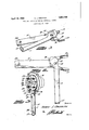
Fig. 1 is a perspective view of the improved tool in the partially closed position.
Fig. 2 is a plan view of the toolin the open position. 7
Fig. 3 illustrates the tool in use upon a typical universal joint assembly.
The invention comprises a plier-like tool consisting ofa first handle member 10 and a second handle member 11 secured together upon a pivot pin 12. One extremity of the first handle member 10 is bifurcated so as to form two forwardly projecting furca tions 13. The furcations 13 are bent downwardly for a portion of their length, as shown at 14 and thence extend forwardly substantially parallel to the plane of the handle 10. The
1929. Serial No. 878,638.
furcations13 are relatively thin so that they can be inserted in the space between the hearing cap and the casing of a universal joint.
The second'handle member 11 is formed with an eccentric cam surface 15 at tremity, and with a notch 16 formed immediately behind the cam surface 15. The other extremity of the second handle member 11 opening the tool when the two handles are in alignment with each other.
The first handle member 10 is provided with a stop 18 which may be formed by indenting a portion'of the metal thereof. The stop 18 serves to limit the amount of opening of the tool, as illustrated in Fig. 2. When in the fully opened position the notch 16 aligns with the n'otchbetween the furcations 13015 the first handle member 10.
One-half of a typical universal joint is illustrated in Fig. 3. In this view half of the joint casing is illustrated at 19; half of the joint bearing, herein designated as a bearing cap, at 20; and one of the joint knuckles at 21. The bearing cap 20 is provided with sockets 22 for receiving the journal extremities 23 of the joint knuckles and with studs 25 for securing the remaining bearing cap (not shown) in place over the assembled knuckles.
When the joint is disassembled the bearing cap 20 falls back into the case 19 and it isdiflicult to "reach this half and bring it and hold itin positionwhile placing the other knuckle and the other bearing cap thereon.
In using this invention the furcations 13 are inserted between the casing 19 and the edge of the bearing cap 20. The handle members are then forcedtoward the casing 19 to cause the fur-cations 13 to engage the back of the bearing cap 20 to bring it against the back side of the journals 23. When in this position the lower handle member 11 is closed causing the cam surface 15 to engage the ex tremity of a journal 23. This firmly locks the tool in the position illustrated in Fig. 3, so that it can bereleased and the mechanic can employ both of his hands to place the other knuckle and the remaining half of the bearing in position. The surfaces of the its exis turned, as shown at 17 to facilitate furcations 13 are slightly inclined toward the axis of the tool as shown in Figs. 1 and 2 to conform to the curvature of the back of the bearing cap 20.
It is now a simple matter to place the other joint knuckle in the sockets 22 and secure the other bearing cap in place upon the studs 25. When the bearing has been assembled and the retaining nuts tightened the handle members can be opened and the tool easily removed from position. When in thefully' open position the notch 16 allows the tool to pass readily over the extremity of one of the ournals 23, so that it can be readily swung to a position which will allow the furcations 13 to be disengaged.
It is the usual custom in assembling a universal to wedge the bearing cap 20 in place and with the back wheel of the automobile jacked up, turn the other bearing cap to align it therewith. When using this invention it is not necessary to jack upthe wheels, since the half of the bearing cap on. the gear box can be turned to the proper position and locked in place by means of the tool so that the remaining cap will fit thereover without rotating the shaft. 7
The turned extremity 17 forms a very handy tool for taking up. the bushing screw in automobile drag links.
The handle member is useful as a separate unit and can be employed to carry out the above operation without the second handle member 11 but if used alone it must be held in place by the operator while the universal joint is being assembled.
While a specific form of the improvement has been described and illustrated herein, it is desired to be understood that the same may be varied, within the scope of the appended claims, without departing from the spirit of the invention- Having thus described the invention, what is claimed and desired secured by Letters Patent is 1- A tool for assemblingv universal joints of the type having a casing and a joint knuckle bearing cap within said casing comprising: a first handle member; forked extremities formed on said handle member and arranged for insertion. to a position between said cap and said casing; and a second handle member pivotedto swing parallel to said first handle member and arranged .to lock said extremities in position, said second handle member being notched so that when in the open position said notch will align between said extremities and when in the closed position it will be swung laterally to one side.
2. An assembling tool comprising: a relatively fiat first handle member; a bifurcated extremity on said handle member. each of the furcations of which extends in the plane of said handle member for a portion of its length, substantiallyat right angles to" the plane of said handle member for another portion of its length, thence forwardly substantially parallel to the plane of said handle for the remaining portion of its length; a second handle member pivoted on said first handle member so as to swing in a plane parallel with the surface of said first handle member; and a projecting surface on said second handle member adapted toswing into said bifurcated extremity as said two handle members are'brought into alignment so as to reduce the depth of the notch between said furca- 'tions.
3. An assembling tool comprising: a relatively flat first handle member; a bifurcated extremity on said handle, member, each of the furcations of which extends in the plane of said handle member for a portion of its length, substantially at right angles to the plane of said handle member for another portion. of its length, thence forwardly substantially parallel to. the plane of said handle for the remaining portion of its length; a second handle member pivoted on said first handle member; and a cam surface on said second a handle member adapted to gradually decrease the depth of the notch between said furcations as said handle members are brought into alignment.
4;. An assembling tool comprising: a rela- 11' tively fiat first handle member a bifurcated extremity on said handle member, each of the furcations of which extends in the, plane of said handle member for a portion of its length, substantially at right angles to the 12 1 plane of said handle member for another por tion of its length, thence, forwardly substantially parallel to the plane of said handle for the remaining portion of its length; a second handle member pivoted on said first handle member; and a cam surface on said second handle member adapted to gradually decrease the depth of the notch between said furcations as said handle members are brought into alignment, said second handle member comprising: a relatively thin flat unitary member arranged to lie flat against the surface of said first handle member when in the closed position.
5. An assembling tool comprising: a relat-ively flat first handle member; a bifurcated extremity on said handle member, each of the furcations of which extends in the plane of said handle member for a portion of its length, substantially at right angles to the plane of said handle member for another portion of its length, thence, forwardly substantially parallel to the plane of said handle for the remaining portion of its length; a second handle member pivoted on said first handle member; a cam surface on said second handle member adapted to gradually decrease the depth of said bifurcation as said handle members are brought into alignment, said second handle member comprising: a relatively thin, fiat unitary member arranged to lie fiat against the surface of said first handle member when in the closed position; and a projection on one of said handle members adapted to engage and limit the movement of the other of said handle members.
6. A tool for assembling universal joints.
and the like comprising: a relatively flat first handle member; a bifurcated extremity on said handle member, each of the furcations of which extends in the plane of said handle member for a portion of its length, substantially at right angles to the plane of said handle member for another portion of its length, thence forwardly substantially parallel to the plane of said handle for the remaining portion of its length; and a locking member carried by said handle and adapted to be protruded forwardly from said handle between said furcations so as to extend the plane of said handle forwardly parallel to but in spaced relation from said furcations.
7 A tool for use in assembling universal joints of the type having a bearing cap for a journal within a casing comprising: a bifurcated handle member, the furcations of which are bent so as to extend into said cas mg and engage the rear of said bearing cap to hold the latter outwardly against said journal when said handle member is substantially parallel to the face of said casing; and a locking member adapted to be projected forwardly from said handle member to engage said journal and maintain said handle member in the above described parallel position. V
In testimony whereof, I affix my signature.
HARRY J. GRIFFITH.
Priority Applications (1)
| Application Number | Priority Date | Filing Date | Title |
|---|---|---|---|
| US378638A US1854736A (en) | 1929-07-16 | 1929-07-16 | Tool for use in assembling universal joints |
Applications Claiming Priority (1)
| Application Number | Priority Date | Filing Date | Title |
|---|---|---|---|
| US378638A US1854736A (en) | 1929-07-16 | 1929-07-16 | Tool for use in assembling universal joints |
Publications (1)
| Publication Number | Publication Date |
|---|---|
| US1854736A true US1854736A (en) | 1932-04-19 |
Family
ID=23493925
Family Applications (1)
| Application Number | Title | Priority Date | Filing Date |
|---|---|---|---|
| US378638A Expired - Lifetime US1854736A (en) | 1929-07-16 | 1929-07-16 | Tool for use in assembling universal joints |
Country Status (1)
| Country | Link |
|---|---|
| US (1) | US1854736A (en) |
Cited By (2)
| Publication number | Priority date | Publication date | Assignee | Title |
|---|---|---|---|---|
| USD296750S (en) | 1985-08-14 | 1988-07-19 | George Hamatani | Clearance checking tool for air brake system |
| USD491427S1 (en) | 2002-08-30 | 2004-06-15 | David Weimer | Universal camshaft retainer |
-
1929
- 1929-07-16 US US378638A patent/US1854736A/en not_active Expired - Lifetime
Cited By (2)
| Publication number | Priority date | Publication date | Assignee | Title |
|---|---|---|---|---|
| USD296750S (en) | 1985-08-14 | 1988-07-19 | George Hamatani | Clearance checking tool for air brake system |
| USD491427S1 (en) | 2002-08-30 | 2004-06-15 | David Weimer | Universal camshaft retainer |
Similar Documents
| Publication | Publication Date | Title |
|---|---|---|
| US2439071A (en) | Detachable handle for knives, hatchets, etc. | |
| US1854736A (en) | Tool for use in assembling universal joints | |
| US1748673A (en) | Combination pliers and tool | |
| US942356A (en) | Chain-manipulating tool. | |
| US2103556A (en) | Ratchet wrench | |
| US1324693A (en) | Rim-tool | |
| US1534066A (en) | Extracting tool | |
| US1387215A (en) | Front-fork clip for velocipedes | |
| US1456007A (en) | Valve-stem-key tool | |
| US1612474A (en) | Tongs | |
| US1224801A (en) | Stud extractor and tightener. | |
| WO2004081325A1 (en) | Reinforced lock for an opening on a motor vehicle | |
| US2196929A (en) | Tappet tool | |
| US1735011A (en) | Combination tool | |
| US1316044A (en) | Wrench | |
| US1787424A (en) | Pocket or folding knife | |
| US1888793A (en) | Wrench | |
| US1177302A (en) | Tool. | |
| US1805884A (en) | Wrench | |
| US621293A (en) | George f | |
| US1802666A (en) | Combination screw driver and pliers | |
| US2386342A (en) | Turnbuckle wrench | |
| US731916A (en) | Combination-tool. | |
| US1401615A (en) | Wrench | |
| US1528247A (en) | Plier wrench |