US1851925A - Battery terminal puller - Google Patents
Battery terminal puller Download PDFInfo
- Publication number
- US1851925A US1851925A US572374A US57237431A US1851925A US 1851925 A US1851925 A US 1851925A US 572374 A US572374 A US 572374A US 57237431 A US57237431 A US 57237431A US 1851925 A US1851925 A US 1851925A
- Authority
- US
- United States
- Prior art keywords
- frame
- battery
- pivot
- jaw
- battery terminal
- Prior art date
- Legal status (The legal status is an assumption and is not a legal conclusion. Google has not performed a legal analysis and makes no representation as to the accuracy of the status listed.)
- Expired - Lifetime
Links
Images
Classifications
-
- B—PERFORMING OPERATIONS; TRANSPORTING
- B25—HAND TOOLS; PORTABLE POWER-DRIVEN TOOLS; MANIPULATORS
- B25B—TOOLS OR BENCH DEVICES NOT OTHERWISE PROVIDED FOR, FOR FASTENING, CONNECTING, DISENGAGING, OR HOLDING
- B25B27/00—Hand tools, specially adapted for fitting together or separating parts or objects whether or not involving some deformation, not otherwise provided for
- B25B27/0035—Hand tools, specially adapted for fitting together or separating parts or objects whether or not involving some deformation, not otherwise provided for for motor-vehicles
- B25B27/005—Hand tools, specially adapted for fitting together or separating parts or objects whether or not involving some deformation, not otherwise provided for for motor-vehicles for pulling off battery terminals
-
- Y—GENERAL TAGGING OF NEW TECHNOLOGICAL DEVELOPMENTS; GENERAL TAGGING OF CROSS-SECTIONAL TECHNOLOGIES SPANNING OVER SEVERAL SECTIONS OF THE IPC; TECHNICAL SUBJECTS COVERED BY FORMER USPC CROSS-REFERENCE ART COLLECTIONS [XRACs] AND DIGESTS
- Y10—TECHNICAL SUBJECTS COVERED BY FORMER USPC
- Y10T—TECHNICAL SUBJECTS COVERED BY FORMER US CLASSIFICATION
- Y10T29/00—Metal working
- Y10T29/53—Means to assemble or disassemble
- Y10T29/53796—Puller or pusher means, contained force multiplying operator
- Y10T29/53804—Battery post and terminal
Definitions
- a further object of this invention is to provide a tool of this nature which is'eXceedingly compact and convenient and in which one of the jaws hasmeans for ad usting the side pressure thereon so that it may bemade to fit the particular battery terminal on which it is being used.
- a further object of this invention is to provide a novel battery cable clamp remover which is operated by a pair of handles in a manner similar to the operation of tongs or pliers and in which each handle provides an equal amount of pushing pressure on the battery post and of pulling pressure on the cable clamp.
- this invention comprises the constructions
- Figure 1 is a plan view of this improved battery cable remover
- Figure 2 is a side view of Figure 1 looking from the right side thereof,
- Figure 3 is a bottom plan view of Figure 2
- Figure 4 is an enlarged broken plan view of the jaws opened ready to engage a battery cable clamp and terminal
- Figure 5 is a perspective view of the device as applied to a battery. 9
- a pair of operating handles or levers Pivoted to the handle 10 at 12 is a jaw 14 and pivoted tothe other handle 11 as at 15 is a second jaw 16, the jaws 1 1 and 16 each terminating in an inturned tooth 17 and 18.
- a pair of spacing washers 12' may be provided on opposite sides of the jaw 14 about pivot 12.
- the teeth 17 and 18 and the aws likewise are preferably case hardened.
- the handles 10 and 11 are pinned together by a pivot 19 passing through projecting hollow flanges 20 and 21 thereof, the pivot 19 also passing through the push rod 22.
- a U- s'haped plate 23 passes about both jaws and push rod, being pivoted tothe jaw, 14 at'24.
- a pair of pivot pins 25 pass through the frame 23 and through a longitudinal slot 26 in the push rod 22'and serve to guide the push rod in an upward and downward direction;
- the plate 23 is slotted as at 27 in a direction transverse of the jaw and a pin 28 passes through this slot 27 and the jaw 16 and through 6:
- a bolt 29 passes through a slotted opening in the U-end of plate 23 and an opening in the U-end of the plate 28, being held in position thereon by a wing-nut 30 and a compression spring3lk In operation, the batteryn-ut which serves to hold the split cable clamp 32 on thebattery post 33 is slightly unscrewed.
- the handles 10 and 11 are each grasped in one hand and 7 opened wide to the position shown in Figure 4, and placedwith the push rod 22 resting ,on the top of the battery post '33, while the aws 14 and 16 each pass on opposite sides of the cable clamp 32 with the teeth 17 and 18 coming thereunder, the wingnut 30 having been previously properly adjusted to allow the teeth 17 and 18 to just pass under the outsides of the clamp 33.
- a tool of the class described comprising a pair of handles, a push rod, said handles beingpivote'd to each other and to saidpush rod by-a commonpivot, a Jaw independefitly' pivotedto each'handle, a guiding frame aflixed'to said jaws; and p'ushrod, said guiding'frame being- Ui-shaped, said'affixing means comprising a plvOil through 'saidframe and one of sa1d aws,a pair of p1vots afliXedin said frame and passingthrough a longitudinal slot in said pu'shrod, a "pivot through said frame and said second jaw; said latter pivot passing throughra transverse slot in said U-shaped frame, a second U-shaped frame about the U endofsaid first frame,
- said means comprising a" bolt'aflixe'd i'n'sai'cl first U-fra'me'andextending through an'opening in the- U ofsaid second U frame,
Landscapes
- Engineering & Computer Science (AREA)
- Mechanical Engineering (AREA)
- Connection Of Batteries Or Terminals (AREA)
Description
March 29, 1932. J R 1,851,925
BATTERY TERMINAL FULLER Filed Oct, 51, 1951 gwuemtoo Jo/m Bic/aard- Patented Mar. 29, 1932 UNITED STATES PATENT OFFICE.
JOHN RICHARD, OF CHICAGO, ILLINOIS BATTERY; TERMINAL PUL'LER Application filed October 31, 1931. Se'ria1 No. 572,374.
terminal post of a storage battery.
A further object of this invention is to provide a tool of this nature which is'eXceedingly compact and convenient and in which one of the jaws hasmeans for ad usting the side pressure thereon so that it may bemade to fit the particular battery terminal on which it is being used. c
A further object of this invention is to provide a novel battery cable clamp remover which is operated by a pair of handles in a manner similar to the operation of tongs or pliers and in which each handle provides an equal amount of pushing pressure on the battery post and of pulling pressure on the cable clamp.
With the foregoing and other objects in view, as will hereinafter become apparent,
this invention comprises the constructions,
combinations and arrangements of arts, hereinafter set forth, claimed and s iown on the accompanying drawings. In these drawings,
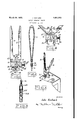
Figure 1 is a plan view of this improved battery cable remover,
Figure 2 is a side view of Figure 1 looking from the right side thereof,
Figure 3 is a bottom plan view of Figure 2,
Figure 4 is an enlarged broken plan view of the jaws opened ready to engage a battery cable clamp and terminal, and
Figure 5 is a perspective view of the device as applied to a battery. 9
There is shown at 10 and 11 a pair of operating handles or levers. Pivoted to the handle 10 at 12 is a jaw 14 and pivoted tothe other handle 11 as at 15 is a second jaw 16, the jaws 1 1 and 16 each terminating in an inturned tooth 17 and 18. A pair of spacing washers 12' may be provided on opposite sides of the jaw 14 about pivot 12. The teeth 17 and 18 and the aws likewise are preferably case hardened.
The handles 10 and 11 are pinned together by a pivot 19 passing through projecting hollow flanges 20 and 21 thereof, the pivot 19 also passing through the push rod 22. A U- s'haped plate 23 passes about both jaws and push rod, being pivoted tothe jaw, 14 at'24. A pair of pivot pins 25 pass through the frame 23 and through a longitudinal slot 26 in the push rod 22'and serve to guide the push rod in an upward and downward direction; The plate 23 is slotted as at 27 in a direction transverse of the jaw and a pin 28 passes through this slot 27 and the jaw 16 and through 6:
an additional but smaller U-shaped plate 28,
to which the ends are afiixed. A bolt 29 passes through a slotted opening in the U-end of plate 23 and an opening in the U-end of the plate 28, being held in position thereon by a wing-nut 30 and a compression spring3lk In operation, the batteryn-ut which serves to hold the split cable clamp 32 on thebattery post 33 is slightly unscrewed. The handles 10 and 11 are each grasped in one hand and 7 opened wide to the position shown in Figure 4, and placedwith the push rod 22 resting ,on the top of the battery post '33, while the aws 14 and 16 each pass on opposite sides of the cable clamp 32 with the teeth 17 and 18 coming thereunder, the wingnut 30 having been previously properly adjusted to allow the teeth 17 and 18 to just pass under the outsides of the clamp 33. Then the mere act of pressing the handles 10 and 11 toward each other will serve to press the push rod 22 downwardly through the medium of the interconnecting pivoting pin 19 and pull the jaws 14 and 16 upward through the medium of the connecting pivoting pins 12 and 15, thereby quickly 8:; and easily removing the battery clamp 32 from the battery-post 33 no matter how the same may have been covered with corrosion from the battery acids.
As will be obvious, the entire pressure or .90 force will be exerted in pulling the cable clamp 32 away from the battery post 33 without tending to affect the position of the battery post 33 in the battery or to loosen the same whatsoever. 9
The novel features and the operation of i this device will be apparent from the foregoing description. While the device has been shown and the structure described in detail, it is obvious that this is not to be considered limited to the exact form disclosed and that red by a common pivot, a jaw independently pivoted to each handle, a guiding frame affixed to said jaws and push rod, said guiding frame being U-shaped, said aflixing means comprising a pivot through said frame: and one of said jaws, a pair of pivots affixed in said frame and'passing through a'longitu'dinal slot, in said push'rod, apivotthrough 1 saidframe and said'secondijaw, said latter pivot passing through a transverse slot-in said U-shaped frame, a second U-shaped frame about the 'U-en'd of said first frame,
said latter pivot being affixed in said second Ushaped frame, and means for adjusting the position of said latter pivot in said transverse slotof said first frame. 2. A tool of the class described comprising a pair of handles, a push rod, said handles beingpivote'd to each other and to saidpush rod by-a commonpivot, a Jaw independefitly' pivotedto each'handle, a guiding frame aflixed'to said jaws; and p'ushrod, said guiding'frame being- Ui-shaped, said'affixing means comprising a plvOil through 'saidframe and one of sa1d aws,a pair of p1vots afliXedin said frame and passingthrough a longitudinal slot in said pu'shrod, a "pivot through said frame and said second jaw; said latter pivot passing throughra transverse slot in said U-shaped frame, a second U-shaped frame about the U endofsaid first frame,
means fora'djusting the position of said latter pivot in "said transverse slot of said-"first frame, said means comprising a" bolt'aflixe'd i'n'sai'cl first U-fra'me'andextending through an'opening in the- U ofsaid second U frame,
nut means on saidbolt, and a compression spring between sa1d nut means' and'said-second U-shaped frame.
In testimony whereofI afiix myfsignature. JOHN RICHARD;
Priority Applications (1)
| Application Number | Priority Date | Filing Date | Title |
|---|---|---|---|
| US572374A US1851925A (en) | 1931-10-31 | 1931-10-31 | Battery terminal puller |
Applications Claiming Priority (1)
| Application Number | Priority Date | Filing Date | Title |
|---|---|---|---|
| US572374A US1851925A (en) | 1931-10-31 | 1931-10-31 | Battery terminal puller |
Publications (1)
| Publication Number | Publication Date |
|---|---|
| US1851925A true US1851925A (en) | 1932-03-29 |
Family
ID=24287520
Family Applications (1)
| Application Number | Title | Priority Date | Filing Date |
|---|---|---|---|
| US572374A Expired - Lifetime US1851925A (en) | 1931-10-31 | 1931-10-31 | Battery terminal puller |
Country Status (1)
| Country | Link |
|---|---|
| US (1) | US1851925A (en) |
-
1931
- 1931-10-31 US US572374A patent/US1851925A/en not_active Expired - Lifetime
Similar Documents
| Publication | Publication Date | Title |
|---|---|---|
| US2815777A (en) | Spring actuated miter clamp | |
| DE3490450T (en) | Instrument for inserting surgical fasteners | |
| US4088313A (en) | Spring actuated woodworking clamp | |
| US3314319A (en) | Pliers-type hand tool | |
| US2462250A (en) | Staple puller | |
| US2838973A (en) | Releasing means for self-locking plier type toggle wrench | |
| US4293119A (en) | Tool for removing staples | |
| US1851925A (en) | Battery terminal puller | |
| US2722858A (en) | Lever actuated rod bending tool with work clamping means | |
| US2144180A (en) | Pliers | |
| US2486851A (en) | Puller | |
| US3119597A (en) | Gripping device | |
| US1983050A (en) | Clamping device | |
| US1735011A (en) | Combination tool | |
| US2455517A (en) | Double-acting chain-type pipe vise | |
| US2507622A (en) | Spring engaging hook assembly for brake spring tools | |
| US3153357A (en) | Cotter pin bending tool | |
| US2799191A (en) | Multiple range compound action hand tool | |
| US2112193A (en) | Parallel motion tool | |
| US2646709A (en) | Pivoted jaw wrench | |
| US1949343A (en) | Applying and removing tool | |
| US1520613A (en) | Pliers | |
| CH213774A (en) | Electric spot welding device. | |
| US1691353A (en) | Clip-attaching tool | |
| US2514802A (en) | Self-closing clamping implement |