US12296463B2 - Systems and methods for object processing using a vacuum gripper that provides object retention by shroud inversion - Google Patents
Systems and methods for object processing using a vacuum gripper that provides object retention by shroud inversion Download PDFInfo
- Publication number
- US12296463B2 US12296463B2 US18/601,171 US202418601171A US12296463B2 US 12296463 B2 US12296463 B2 US 12296463B2 US 202418601171 A US202418601171 A US 202418601171A US 12296463 B2 US12296463 B2 US 12296463B2
- Authority
- US
- United States
- Prior art keywords
- effector
- continuous
- shroud
- motion device
- collapsible dome
- Prior art date
- Legal status (The legal status is an assumption and is not a legal conclusion. Google has not performed a legal analysis and makes no representation as to the accuracy of the status listed.)
- Active
Links
Images


Classifications
-
- B—PERFORMING OPERATIONS; TRANSPORTING
- B25—HAND TOOLS; PORTABLE POWER-DRIVEN TOOLS; MANIPULATORS
- B25J—MANIPULATORS; CHAMBERS PROVIDED WITH MANIPULATION DEVICES
- B25J15/00—Gripping heads and other end effectors
- B25J15/06—Gripping heads and other end effectors with vacuum or magnetic holding means
- B25J15/0616—Gripping heads and other end effectors with vacuum or magnetic holding means with vacuum
- B25J15/0683—Details of suction cup structure, e.g. grooves or ridges
-
- B—PERFORMING OPERATIONS; TRANSPORTING
- B25—HAND TOOLS; PORTABLE POWER-DRIVEN TOOLS; MANIPULATORS
- B25J—MANIPULATORS; CHAMBERS PROVIDED WITH MANIPULATION DEVICES
- B25J15/00—Gripping heads and other end effectors
- B25J15/0023—Gripper surfaces directly activated by a fluid
-
- B—PERFORMING OPERATIONS; TRANSPORTING
- B25—HAND TOOLS; PORTABLE POWER-DRIVEN TOOLS; MANIPULATORS
- B25J—MANIPULATORS; CHAMBERS PROVIDED WITH MANIPULATION DEVICES
- B25J15/00—Gripping heads and other end effectors
- B25J15/0028—Gripping heads and other end effectors with movable, e.g. pivoting gripping jaw surfaces
-
- B—PERFORMING OPERATIONS; TRANSPORTING
- B65—CONVEYING; PACKING; STORING; HANDLING THIN OR FILAMENTARY MATERIAL
- B65G—TRANSPORT OR STORAGE DEVICES, e.g. CONVEYORS FOR LOADING OR TIPPING, SHOP CONVEYOR SYSTEMS OR PNEUMATIC TUBE CONVEYORS
- B65G47/00—Article or material-handling devices associated with conveyors; Methods employing such devices
- B65G47/74—Feeding, transfer, or discharging devices of particular kinds or types
- B65G47/90—Devices for picking-up and depositing articles or materials
- B65G47/91—Devices for picking-up and depositing articles or materials incorporating pneumatic, e.g. suction, grippers
-
- B—PERFORMING OPERATIONS; TRANSPORTING
- B25—HAND TOOLS; PORTABLE POWER-DRIVEN TOOLS; MANIPULATORS
- B25J—MANIPULATORS; CHAMBERS PROVIDED WITH MANIPULATION DEVICES
- B25J9/00—Program-controlled manipulators
- B25J9/0093—Program-controlled manipulators co-operating with conveyor means
Definitions
- the invention generally relates to programmable motion systems and relates in particular to end effectors for programmable motion devices (i.e., robotic systems) for use in object processing such as object sortation and object distribution.
- programmable motion devices i.e., robotic systems
- End effectors for robotic systems may be employed in certain applications to select and grasp an object, and then move the acquired object very quickly to a new location.
- End effectors that are designed to very securely grasp an object during movement may have limitations regarding how quickly and easily they may select and grasp an object from a jumble of dissimilar objects.
- end effectors that may quickly and easily grasp a selected object from a jumble of dissimilar objects may have limitations regarding how securely they may grasp an acquired object during rapid movement, particularly rapid acceleration and deceleration (both angular and linear).
- Vacuum grippers generally require having a good seal with an object, but ensuring a good seal sometimes requires that the particular suction cup be selected to correspond to the object being grasped. Additionally, grasping certain objects, such as plastic bags, may require a specific type of end effector to ensure that the plastic bag does not peel off of the end effector or collapse under the force of the end effector and thereby break the bag and/or the seal. Further, the lifting force may be limited by an amount proportional to the area of contact of the suction cup in a vacuum system, and the vacuum itself may damage some objects.
- End effectors are generally designed as a single tool, such as for example, a gripper, a welder, or a paint spray head, and the tool is typically designed for a specific set of needs. There remains a need for an end effector in a programmable motion system that may select and grasp an object, and then move the acquired object very quickly to a new location.
- the invention provides an end-effector of a programmable motion device.
- the end-effector includes a body that provides an open interior, the open interior being coupled to a vacuum source, and the body including a contact surface for contacting an object to be grasped by the end effector.
- the contact surface includes at least one aperture through which a vacuum is provided, and the body includes an outer surface that faces away from the open interior. The body provides that when the flow of air drawn by the vacuum source through the at least one aperture is reduced due to the at least one aperture being at least partially blocked, the outer surface of the body engages the object being grasped at least partially within the open interior of the body
- the invention provides an end-effector of a programmable motion device, where the end-effector includes a body that provides an open interior, the open interior being coupled to a vacuum source.
- the body also includes a gripping shroud for contacting an object to be grasped by the end effector, the gripping shroud including an outer portion that is adapted to move from a position facing away from the open interior, to a position drawn inward at least partially toward the open interior to engage an object at least partially within the open interior of the body.
- the invention provides a method of applying an end-effector of a programmable motion device to an object.
- the method includes providing an end-effector including a body that provides an open interior, the open interior being coupled to a vacuum source, and the body including a contact surface for contacting an object to be grasped by the end effector, and the contact surface including at least one aperture, engaging the contact surface of the flexible body to the object, and permitting at least a portion of the contact surface of the flexible body to be drawn at least partially into the open interior of the body when a flow of air drawn by the vacuum source through the aperture is reduced due to the aperture being at least partially blocked.
- FIG. 1 shows and illustrative diagrammatic view of an object processing system including a programmable motion device with an end effector in accordance with as aspect of the present invention
- FIG. 2 shows an illustrative diagrammatic underside view of the perception system of FIG. 1 ;
- FIG. 3 shows an illustrative diagrammatic view of a bin of objects to be processed from the perception system of FIG. 1 ;
- FIG. 4 shows an illustrative diagrammatic front view of the end effector of FIG. 1 in accordance with an aspect of the present invention
- FIG. 5 shows an illustrative diagrammatic bottom view of the end effector of FIG. 4 taken along line 5 - 5 thereof;
- FIG. 6 shows an illustrative diagrammatic side sectional view of the end effector of FIG. 4 taken along line 6 - 6 thereof;
- FIG. 7 shows an illustrative diagrammatic side sectional view of the end effector of FIG. 6 contacting an object
- FIG. 8 shows an illustrative diagrammatic side sectional view of the end effector of FIG. 7 beginning to draw in the object
- FIG. 9 shows an illustrative diagrammatic side sectional view of the end effector of FIG. 7 further drawing in the object;
- FIG. 10 shows an illustrative diagrammatic side sectional view of the end effector of FIG. 7 having fully drawn in the object
- FIG. 11 shows an illustrative diagrammatic side sectional view of the end effector of FIG. 6 having fully drawn in a non-round object
- FIG. 12 shows an illustrative diagrammatic side sectional view of the end effector of FIG. 6 having drawn in a larger non-round object
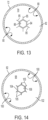
- FIG. 13 shows an illustrative diagrammatic bottom view of an end-effector in accordance with another aspect of the invention that includes a polygonal aperture
- FIG. 14 shows an illustrative diagrammatic bottom view of an end-effector in accordance with another aspect of the invention that includes a polygonal aperture and relief openings;
- FIG. 15 shows an illustrative diagrammatic bottom view of an end-effector in accordance with another aspect of the invention that includes a generally triangular-shaped aperture
- FIG. 16 shows an illustrative diagrammatic bottom view of an end-effector in accordance with another aspect of the invention that includes a generally triangular-shaped and relief openings;
- FIG. 17 shows an illustrative diagrammatic side sectional view of the end effector in accordance with another aspect of the invention that includes a flexible portion at an intermediate location along a distal wall;
- FIG. 19 shows an illustrative diagrammatic bottom view of the end effector of FIG. 17 taken along line 19 - 19 thereof;
- FIG. 20 shows an illustrative diagrammatic front view of an end-effector of a further aspect of the present invention that is elongated
- FIG. 21 shows an illustrative diagrammatic sectional view of the elongated end-effector of FIG. 20 taken along line 21 - 21 thereof;
- FIG. 22 shows an illustrative diagrammatic sectional view of the elongated end-effector of FIG. 20 taken along line 22 - 22 thereof;
- FIG. 23 shows an illustrative diagrammatic bottom view of the elongated end-effector of FIG. 20 ;
- FIG. 24 shows an illustrative diagrammatic bottom view of an elongated end-effector in accordance with a further aspect of the invention in a view similar to that of FIG. 23 ;
- FIG. 25 shows an illustrative diagrammatic front view of the elongated end-effector of FIG. 20 while grasping an elongated object
- FIG. 26 shows an illustrative diagrammatic sectional view of the elongated end-effector of FIG. 25 taken along line 26 - 26 thereof;
- FIG. 27 shows an illustrative diagrammatic bottom view of the elongated end-effector of FIG. 25 taken along line 27 - 27 thereof;
- FIG. 28 shows an illustrative diagrammatic side sectional view of an elongated end effector in accordance with another aspect of the invention that includes a flexible portion at an intermediate location along a distal wall;
- FIG. 29 shows an illustrative diagrammatic side sectional view of the end effector of FIG. 28 contacting an object
- FIG. 30 shows an illustrative diagrammatic isometric view of an end effector in accordance with a further aspect of the present invention that includes a collapsible dome and a shroud;
- FIG. 31 shows an illustrative diagrammatic view of the end effector of FIG. 30 while grasping
- FIG. 32 shows an illustrative diagrammatic side view of the end effector of FIG. 30 ;
- FIG. 33 shows an illustrative diagrammatic bottom view of the end effector of FIG. 30 ;
- FIG. 34 shows an illustrative diagrammatic side view of an end effector in accordance with a further aspect of the present invention that includes a collapsible dome and a shroud with a scalloped edge;
- FIG. 35 shows an illustrative diagrammatic side view of an end effector in accordance with a further aspect of the present invention that includes a shroud and a collapsible dome that extends beyond the shroud prior to grasping;
- FIG. 36 shows an illustrative diagrammatic side view of the end effector of FIG. 30 while grasping
- FIG. 37 shows an illustrative diagrammatic bottom view of the end effector of FIG. 36 ;
- FIG. 38 shows an illustrative diagrammatic side view of the end effector of FIG. 30 while grasping a deformable object
- FIG. 39 shows an illustrative diagrammatic side view of the end effector of FIG. 30 while grasping a rigid object
- FIG. 40 shows an illustrative diagrammatic side view of an end effector in accordance with a further aspect of the present invention that includes a collapsible dome with fewer apertures, a shroud, and extension regions;
- FIG. 41 shows an illustrative diagrammatic side view of an end effector in accordance with a further aspect of the present invention that includes a collapsible dome with fewer apertures, a shroud, extension regions, and additional braces;
- FIG. 42 shows an illustrative diagrammatic side view of an end effector in accordance with a further aspect of the present invention that includes a coupling attached to a flexible body;
- FIG. 43 shows an illustrative diagrammatic sectional side view of flexible body of FIG. 42 with inner circumferential support ribs;
- FIG. 44 shows an illustrative diagrammatic sectional side view of flexible body of FIG. 42 with axially extending support ribs
- FIG. 45 shows an illustrative diagrammatic elevational isometric view of flexible body of FIG. 42 with a stop member
- FIG. 46 shows an illustrative diagrammatic side view of flexible body and stop member of FIG. 45 .
- the invention provides an end-effector of a programmable motion device that includes a body that provides an open interior.
- the open interior is coupled to a vacuum source, and the body includes a contact surface for contacting an object to be grasped by the end effector.
- the contact surface at least partially defines an aperture
- the body includes a flexible portion that permits the contact surface to be drawn at least partially into the open interior of the body when a flow of air drawn by the vacuum source through the aperture is reduced due to the aperture being at least partially blocked.
- the flexible portion provides a joint region about which an outer surface adjacent the contact surface may move inward into the open interior.
- the outer surface faces away from the open interior, yet when the flow of air drawn by the vacuum source through the aperture is reduced due to the aperture being at least partially blocked, the outer surface of the flexible portion faces the object being grasped.
- FIG. 1 shows an object processing system 10 that includes an object processing station 12 between an infeed conveyor 16 that carries infeed bins 14 , and a destination conveyor 20 that carries destination containers 18 .
- the object processing station 12 includes a programmable motion device (e.g., an articulated arm 22 ) with an attached end-effector 24 as well as an associated perception system 26 .
- the perception system 26 is positioned to perceive objects (and/or associated indicia) in selected infeed bins 14 ′ that are diverted (selected) by diverter 17 to move along selected infeed conveyor 16 ′.
- the perception system 26 is positioned as well to perceive destination containers 18 ′ that are provided on a processing destination conveyor section 20 ′ of the destination conveyor 20 . Operation of the system is controlled by one or more computer processing systems 100 that communicate with the conveyors 16 , 16 ′ diverter 17 , conveyor 20 , programmable motion device 22 (including the end-effector 24 ) and perception system 26 .
- the object processing station 12 includes an infeed conveyor section 16 ′ that circulates supply bins 14 ′ from and back to the infeed conveyor 16 using the diverter 17 .
- the end-effector 24 of the programmable motion device 22 is programmed to grasp an object from a supply bin 14 ′, and move the object to deliver it to a desired destination bin 18 on the destination conveyor load area 20 ′ by placing or dropping the object into the destination container 18 ′ at the destination conveyor load area 20 ′.
- the supply bin 14 ′ may then be returned to the input conveyor 16 and, optionally, brought to a further processing station.
- one or more vendor supply bins 14 are routed to an input area, and the programmable motion device 22 is actuated to grasp an object from a bin 14 ′, and to place the object into a selected destination container 18 ′.
- the processed vendor bins 14 ′ are then returned to the common input stream on the conveyor 16 , and the destination container 18 ′ is moved further along the destination conveyor 20 .
- the system 10 may also include one or more perception units 19 located on or near the infeed conveyor 16 for identifying indicia on an exterior of each of the bins 14 , providing perception data from which the contents of the bin may be identified, and then knowing its relative position on the conveyor 16 , track its location. It is assumed, in accordance with an aspect, that the bins of objects are marked in one or more places on their exterior with a visually distinctive mark such as a barcode (e.g., providing a UPC code), QR code, or radio-frequency identification (RFID) tag or mailing label so that they may be sufficiently identified with a scanner for processing.
- a barcode e.g., providing a UPC code
- QR code e.g., QR code
- RFID radio-frequency identification
- the types of scanners employed are assumed to be compatible with the marking approach.
- the marking e.g. by barcode, RFID tag, mailing label or other means, encodes a identifying indicia (e.g., a symbol string), which is typically a string of letters and/or numbers.
- the symbol string uniquely associates the vendor bin with a specific set of homogenous objects.
- the system may either permit a bin 14 to continue along the infeed conveyor 16 , or using diverter 17 , may direct the selected bin 14 ′ onto the selected infeed conveyor 16 ′.
- each object may also be marked with a visually distinctive mark, again such as a barcode (e.g., providing a UPC code), QR code, or radio-frequency identification (RFID) tag or mailing label so that they may be sufficiently identified with a scanner for processing.
- a visually distinctive mark again such as a barcode (e.g., providing a UPC code), QR code, or radio-frequency identification (RFID) tag or mailing label so that they may be sufficiently identified with a scanner for processing.
- the type of marking depends on the type of scanning system used, but may include 1D or 2D code symbologies. Again, multiple symbologies or labeling approaches may be employed on each object.
- the perception system 26 that looks down in the object processing station 12 perceives perception data from one or more objects with the selected infeed bin 14 ′ on the selected infeed conveyor 16 ′.
- the perception system 26 is mounted above a bin of objects to be processed next to the base of the articulated arm 22 , looking down into a bin 32 .
- the perception system 26 may include (on the underside thereof), a camera 27 , a depth sensor 28 and lights 30 .
- a combination of 2D and 3D (depth) data is acquired.
- the depth sensor 28 may provide depth information that may be used together with the camera image data to determine depth information regarding the various objects in view.
- the lights 30 may be used to remove shadows and to facilitate the identification of edges of objects, and may be all on during use, or may be illuminated in accordance with a desired sequence to assist in object identification.
- the system uses this imagery and a variety of algorithms to generate a set of candidate grasp locations for the objects in the bin as discussed in more detail below.
- FIG. 3 shows a view of the bin 14 ′ from the perception system 26 .
- the image view shows the bin 14 ′ (e.g., on the conveyor 16 ′), and the bin 14 ′ contains objects 32 , 34 , 36 and 38 .
- the objects in each infeed bin may be homogenous, in other systems, such as shown in FIG. 3 , the objects may be non-homogenous.
- the system will identify candidate grasp locations on one or more objects, and may not try to yet identify a grasp location for the object that is partially obscured by other objects.
- Candidate grasp locations may be indicated using a 3D model of the robot end effector placed in the location where the actual end effector would go to use as a grasp location.
- Grasp locations may be considered good, for example, if they are close to the center of mass of the object to provide greater stability during grasp and transport, and/or if they avoid places on an object such as caps, seams, etc. where a good vacuum seal might not be available.
- the perception system considers the object to be two different objects, and may propose more than one candidate grasp of such two different objects. If the system executes a grasp at either of these bad grasp locations, it will either fail to acquire the object due to a bad grasp point where a vacuum seal will not occur, or will acquire the object at a grasp location that is very far from the center of mass of the object and thereby induce a great deal of instability during any attempted transport. Each of these results is undesirable.
- the system may remember that location for the associated object. By identifying good and bad grasp locations, a correlation is established between features in the 2D/3D images and the idea of good or bad grasp locations. Using this data and these correlations as input to machine learning algorithms, the system may eventually learn, for each image presented to it, where to best grasp an object, and where to avoid grasping an object.
- a central control system 100 that again communicates (e.g., wirelessly) with the articulated arm 22 , the perception units 19 , 26 , 28 and 30 , as well as in-feed conveyors 16 , 16 ′, diverter 17 and destination conveyor 20 .
- This system determines from symbol strings the UPC associated with a vendor bin, as well as the outbound destination for each object.
- the central control system 100 is comprised of one or more workstations or central processing units (CPUs).
- CPUs central processing units
- the central control system maintains the manifest by communicating with a warehouse management system (WMS).
- the manifest provides the outbound destination for each in-bound object.
- the end-effector 24 of FIG. 1 is shown in FIG. 4 coupled to the end-effector mounting section 40 of the programmable motion device 22 .
- the end-effector 24 includes a body 42 and a connection portion 44 for coupling to the end-effector mounting section 40 .
- the body 42 includes a proximate wall 46 that is coupled to the connection portion 44 , and the proximate wall 46 is also coupled to a distal wall 48 via a flexible section 50 .
- the distal wall 48 includes an outer facing portion 52 , and ends in forming a contact surface 54 that defines an aperture 56 .
- the interior of the body 42 (within the inside of the proximate wall 46 and the distal wall 48 ) provides an open interior 58 .
- the flexible portion 50 of the body 42 may be formed, in accordance with an aspect of the invention, of an elastomeric material, polymeric material, or even metallic material that in the desired shape has sufficient flexibility to permit the distal wall 48 to be drawn up into the interior body 42 due, at least in part, to a vacuum being applied within the interior body while an object is at least partially blocking the aperture 56 as discussed in more detail below.
- the proximate wall 46 and/or the distal wall 48 may also be formed of a material and shape that provides additional flexibility. Generally, a vacuum is provided from the aperture 56 through the opening in the connection portion 44 and the mounting section 40 through a hose 41 to a vacuum source 43 shown in FIG. 1 .
- the vacuum source 43 may be switchable to change to a source of positive air pressure that is pushed from the vacuum source 43 to the aperture 56 to urge both an object away from the contact surface 54 and to push the distal wall 48 distally.
- the flexible portion and/or the proximate wall and/or the distal wall may be formed of a material and shape that provides a desired spring constant.
- the desired spring constant may provide that the body 42 is biased to the shape shown in FIG. 4 such that when deformed (as discussed below with reference to FIGS. 8 - 10 ), the body 42 will act against any deformation, at least partially assisting in causing the body 42 to return to its original shape (again, shown in FIG. 4 ).
- the object may partially or fully block the aperture 56 (shown in FIG. 6 ), causing the object 60 to be grasped by the end-effector due to the vacuum being applied through the aperture 56 , the open interior 58 , and the insides of the end-effector mounting section 40 and hose 41 .
- a result of the aperture 56 being partially or fully blocked, is that the contact surface 54 (and the object) will be drawn into the open interior 58 due, in part, to the vacuum and due, in part, to the flexibility of the flexible portion 50 , and optionally as well as the proximate wall 46 and/or the distal wall 48 .
- FIG. 8 shows the contact surface 54 and the object 60 beginning to enter the open interior 58
- FIG. 9 shows the contact surface 54 and the object 60 further entered in the open interior 58
- FIG. 10 shows the contact surface 54 and the object 60 fully entered into the open interior 58 .
- the object 60 is both held by the vacuum as well as held by the outer surface 52 of the distal wall 48 , as the outer surface 52 of the distal wall 48 now faces the object 60 and aids in containing the object 60 within the end-effector, with the flexible portion 50 having now come underneath at least a portion of the object 60 .
- the release of the object 60 from the end-effector may be accomplished by switching the vacuum to a positive pressure air source that urges the interior 58 to enlarge thereby urging the distal wall 48 radially outward, which causes the distal wall (and the contact surface 54 ) to move outward of the body 42 , pushing the object 60 free of the end-effector 24 .
- the release of the object 60 from the end-effector may be accomplished by switching the vacuum off, and permitting any of the flexible portion 50 , the proximate wall 46 and/or the distal wall 48 that has sufficient spring constant to urge the distal wall 48 radially outward, which causes the distal wall (and the contact surface 54 ) to move outward of the body 42 , pushing the object 60 free of the end-effector 24 .
- FIG. 11 shows the end-effector 24 with the body 42 proximate wall 46 and distal wall 48 holding an object 62 within the outer surface 52 of the distal wall 48 wherein the object 62 does not conform to the shape and contour of the outer surface 52 of the distal wall 48 in accordance with an aspect of the invention.
- FIG. 11 shows the end-effector 24 with the body 42 proximate wall 46 and distal wall 48 holding an object 62 within the outer surface 52 of the distal wall 48 wherein the object 62 does not conform to the shape and contour of the outer surface 52 of the distal wall 48 in accordance with an aspect of the invention.
- 12 further shows the end-effector 24 with the body 42 proximate wall 46 and distal wall 48 holding an object 62 within the outer surface 52 of the distal wall 48 wherein the object 64 not only does not conform to the shape and contour of the outer surface 52 of the distal wall 48 , but further extends at least in part outside of the area defined between the outer surfaces 52 of the distal wall 48 (e.g., extends beyond the flexible portion 50 ).
- the contact surface of the distal wall may be other than circular, and may, for example, form a polygonal shape.
- FIG. 13 shows a bottom view (similar to that shown in FIG. 5 ) of an end-effector is accordance with another aspect of the invention that includes an end-effector that includes a body 72 that includes a proximate wall that is coupled to the connection portion, and the proximate wall is also coupled to a distal wall 78 via a flexible section 80 .
- the distal wall 78 includes an outer facing portion 82 , and ends in forming a contact surface 84 that defines an aperture 86 that is in the shape generally of a polygon.
- the interior of the body 72 (within the inside of the proximate wall and the distal wall 78 ) provides an open interior into which an object may be drawn as discussed above with reference to FIGS. 8 - 10 . Because the aperture 86 is not circular, portions of the outer surface of the distal wall that are proximate sharp directional changes (e.g., corners) of the polygon may form short creases 85 in the outer surface 82 of the distal wall 78 .
- FIG. 14 shows a bottom view (similar to that shown in FIG. 5 ) of an end-effector is accordance with another aspect of the invention that includes an end-effector that includes a body 92 that includes a proximate wall that is coupled to the connection portion, and the proximate wall is also coupled to a distal wall 98 via a flexible section 100 .
- the distal wall 98 includes an outer facing portion 102 , and ends in forming a contact surface 104 that defines an aperture 106 that is in the shape generally of a polygon.
- the interior of the body 92 (within the inside of the proximate wall and the distal wall 98 ) provides an open interior into which an object may be drawn as discussed above with reference to FIGS. 8 - 10 .
- the aperture 106 is not circular, portions of the outer surface of the distal wall that are proximate sharp directional changes (e.g., corners) of the polygon may provide stress on the outer surface, short relief openings 105 may be provided that relieve the stress on the distal wall 98 .
- the opening areas provided by the relief openings may be small enough to not adversely affect the grasp on the object.
- the relief openings 105 may become closed during the movement of the distal wall, increasing the vacuum force upon the object.
- the programmable motion device may assist in such grasping by urging the end-effector onto an object, thereby urging the distal walls inward, closing the relief openings 105 and increasing the vacuum applied to the object.
- the contact surface of the distal wall may form a polygonal, and in particular, a triangular shape, and further the outer shape of the body of the end-effector may also be non-circular.
- FIG. 15 shows a bottom view (similar to that shown in FIG. 5 ) of an end-effector is accordance with another aspect of the invention that includes an end-effector that includes a body 112 that includes a proximate wall that is coupled to the connection portion, and the proximate wall is also coupled to a distal wall 118 via a flexible section 120 .
- the distal wall 118 includes an outer facing portion 122 , and ends in forming a contact surface 124 that defines an aperture 126 that is in the shape generally of a triangle.
- the interior of the body 112 (within the inside of the proximate wall and the distal wall 118 ) provides an open interior into which an object may be drawn as discussed above with reference to FIGS. 8 - 10 .
- the aperture 126 is not circular, any directional changes (e.g., corners) of the triangle may rounded to relieve stress on the outer surface 122 of the distal wall 118 .
- FIG. 16 shows a bottom view (similar to that shown in FIG. 5 ) of an end-effector is accordance with another aspect of the invention that includes an end-effector that includes a body 132 that includes a proximate wall that is coupled to the connection portion, and the proximate wall is also coupled to a distal wall 138 via a flexible section 140 .
- the distal wall 98 includes an outer facing portion 142 , and ends in forming a contact surface 104 that defines an aperture 106 that is in the shape generally of a polygon.
- the interior of the body 132 (within the inside of the proximate wall and the distal wall 138 ) provides an open interior into which an object may be drawn as discussed above with reference to FIGS. 8 - 10 .
- the aperture 146 is not circular, portions of the outer surface of the distal wall that are proximate even rounded directional changes (e.g., corners) of the triangle may provide stress on the outer surface, short relief openings 145 may be provided that relieve the stress on the distal wall 138 .
- the opening areas provided by the relief openings may be small enough to not adversely affect the grasp on the object.
- the relief openings 145 may become closed during the movement of the distal wall, increasing the vacuum force upon the object.
- the programmable motion device may assist in such grasping by urging the end-effector onto an object, thereby urging the distal walls inward, closing the relief openings 145 and increasing the vacuum applied to the object.
- an end-effector may be coupled to the end-effector mounting section of the programmable motion device as discussed above, and may further include a distal wall that includes a flexible portion that is attached not at an end thereof, but at portion intermediate the distal wall.
- FIG. 17 shows a body 152 and a connection portion 154 for coupling to the end-effector mounting section of a programmable motion device as discussed above.
- the body 152 includes a proximate wall 156 that is coupled to the connection portion 154 , and the proximate wall 156 is also coupled to a distal wall 158 via a flexible section 160 .
- the distal wall 158 includes an outer facing portion 162 , and ends in forming a contact surface 164 that defines an aperture 166 .
- the distal wall 158 further includes an outer rim portion 159 .
- the interior of the body 152 (within the inside of the proximate wall and the distal wall 158 ) provides an open interior 168 .
- the flexible portion 160 of the body 152 may be formed, in accordance with an aspect of the invention, of an elastomeric material, polymeric material, or even metallic material that in the desired shape has sufficient flexibility to permit the distal wall 158 to be drawn up into the open interior 168 of the body 152 due, at least in part, to a vacuum being applied within the interior body while an object is at least partially blocking the aperture 171 similar to the examples discussed above.
- the proximate wall 156 and/or the distal wall 158 may also be formed of a material and shape that provides additional flexibility. Generally, a vacuum is provided from the aperture 166 through the opening in the connection portion 154 and the mounting section 40 through a hose 41 to a vacuum source 43 shown in FIG. 1 .
- the vacuum source 43 may be switchable to change to a source of positive air pressure that is pushed from the vacuum source 43 to the aperture 166 to urge both an object away from the contact surface 164 and to push the distal wall 158 distally.
- the flexible portion and/or the proximate wall and/or the distal wall may be formed of a material and shape that provides a desired spring constant.
- the desired spring constant may provide that the body 152 is biased to an original shape such that when deformed (as discussed below with reference to FIG. 18 ), the body 152 will act against any deformation, at least partially assisting in causing the body 152 to return to its original shape (shown in FIG. 17 ).
- the object when the contact surface 164 of the distal wall 158 contacts an object 170 , the object may partially or fully block the aperture 166 (shown in FIGS. 17 and 19 ), causing the object 170 to be grasped by the end-effector due to the vacuum being applied through the aperture 166 , the open interior 168 , and the insides of the end-effector mounting section and hose.
- FIG. 18 shows the contact surface 164 and the object 170 fully entered into the open interior 168 .
- FIG. 19 shows an underside view of the end-effector body 152 of FIG. 17 .
- the object 170 is both held by the vacuum as well as held by the outer surface 162 of the distal wall 158 and the outer rim portion 159 , as the outer surface 162 of the distal wall 158 and the outer rim portion 159 now faces the object 170 and aid in containing the object 170 within the end-effector, with the flexible portion 160 now facing the object 170 on all sides thereof, and the outer rim portion 159 now being at least partially under the object 170 .
- the release of the object 170 from the end-effector may be accomplished by switching the vacuum to a positive pressure air source that urges the open interior 168 to enlarge thereby urging the distal wall 158 radially outward, which causes the distal wall (and the contact surface 164 ) to move outward of the body 152 , pushing the object 170 free of the end-effector.
- the release of the object 170 from the end-effector may be accomplished by switching the vacuum off, and permitting any of the flexible portion 160 , the proximate wall 156 and/or the distal wall 158 that has sufficient spring constant to urge the distal wall 158 radially outward, which causes the distal wall (and the contact surface 164 ) to move outward of the body 152 , pushing the object 170 free of the end-effector.
- the body of the end effector may be elongated.
- FIG. 20 shows an end effector 224 with a body 242 that is elongated, and attaches to a mounting section (e.g., 40 shown in FIG. 1 ) at an attachment section 244 thereof.
- the body 242 may further include recessed portions 243 that may reduce any resistance to the body 242 bending as the body 242 folds in around an object as discussed further below.
- FIGS. 21 and 22 show sectional views of portions of the end effector 224 showing the attachment section 244 (in FIG. 21 ), and a proximate wall 246 that is coupled to the attachment section 244 .
- the proximate wall 246 is also coupled to a distal wall 248 via a flexible section 250 .
- the distal wall 248 includes an outer facing portion 252 , and ends in forming a contact surface 254 that defines an aperture 256 .
- the interior of the body 242 (within the inside of the proximate wall 246 and the distal wall 248 ) provides an open interior 258 .
- the flexible portion 250 of the body 242 may be formed, in accordance with an aspect of the invention, of an elastomeric material, polymeric material, or even metallic material that in the desired shape has sufficient flexibility to permit the distal wall 248 to be drawn up into the interior body 242 due, at least in part, to a vacuum being applied within the interior body while an object is at least partially blocking the aperture 256 as discussed in more detail below.
- the proximate wall 246 and/or the distal wall 248 may also be formed of a material and shape that provides additional flexibility. Generally, a vacuum is provided from the aperture 256 through the opening in the attachment section 244 and the mounting section through a hose to a vacuum source as discussed above.
- the vacuum source may be switchable to change to a source of positive air pressure that is pushed from the source to the aperture 256 to urge both an object away from the contact surface 254 and to push the distal wall 248 distally.
- the flexible portion and/or the proximate wall and/or the distal wall may be formed of a material and shape that provides a desired spring constant.
- the desired spring constant may provide that the body 242 is biased to the shape shown in FIG. 20 such that when deformed (as discussed below with reference to FIGS. 25 - 27 ), the body 242 will act against any deformation, at least partially assisting in causing the body 242 to return to its original shape (again, shown in FIG. 20 ).
- the contact surface 254 may define an elongated opening in accordance with certain aspects of the invention.
- the elongated opening may function to grasp the object via vacuum applied through the elongated opening, drawing the object and the contact surface 254 into the open interior.
- the contact surface 254 ′ may be provided as a plurality of distinct contact surfaces that define a plurality of linearly disposed apertures 256 ′ as shown in FIG. 24 .
- the plurality of linearly disposed apertures may function to grasp the object via vacuum applied through the apertures, drawing the object and the contact surface 254 ′ into the open interior.
- the object may partially or fully block the aperture 256 (or apertures 256 ′) as shown in FIG. 25 , causing the object 263 to be grasped by the end-effector due to the vacuum being applied through the aperture 256 (or apertures 256 ′), the open interior 258 , and the insides of the end-effector mounting section and hose.
- FIG. 25 shows the contact surface 254 (or surfaces 254 ′) and the object 263 fully entered into the open interior 258 .
- FIGS. 26 and 27 show sectional views of the end-effector and object of FIG. 25 .
- the object 263 is both held by the vacuum as well as held by the outer surface 252 of the distal wall 248 , as the outer surface 252 of the distal wall 248 now faces the object 263 and aids in containing the object 263 within the end-effector, with the flexible portion 250 having now come underneath at least a portion of the object 263 .
- the release of the object 263 from the end-effector may be accomplished by switching the vacuum to a positive pressure air source that urges the open interior 258 to enlarge thereby urging the distal wall 248 radially outward, which causes the distal wall (and the contact surface 254 / 254 ′) to move outward of the body 242 , pushing the object 263 free of the end-effector 224 .
- the release of the object 263 from the end-effector may be accomplished by switching the vacuum off, and permitting any of the flexible portion 250 , the proximate wall 246 and/or the distal wall 248 that has sufficient spring constant to urge the distal wall 248 radially outward, which causes the distal wall (and the contact surface 254 / 254 ′) to move outward of the body 242 , pushing the object 263 free of the end-effector 224 .
- an end-effector may be coupled to the end-effector mounting section of the programmable motion device as discussed above, and may further include a distal wall that includes a flexible portion that is attached not at an end thereof, but at portion intermediate the distal wall.
- FIG. 28 shows a body 252 and a connection portion 254 for coupling to the end-effector mounting section of a programmable motion device as discussed above.
- the body 252 includes a proximate wall 257 that is coupled to the connection portion 254 , and the proximate wall 257 is also coupled to a distal wall 261 via a flexible section 260 .
- the distal wall 261 includes an outer facing portion 262 , and ends in forming a contact surface 264 that defines an aperture 266 .
- the distal wall 261 further includes an outer rim portion 259 .
- the interior of the body 252 (within the inside of the proximate wall and the distal wall 261 ) provides an open interior 268 .
- the flexible portion 260 of the body 252 may be formed, in accordance with an aspect of the invention, of an elastomeric material, polymeric material, or even metallic material that in the desired shape has sufficient flexibility to permit the distal wall 261 to be drawn up into the interior 268 of the body 252 due, at least in part, to a vacuum being applied within the interior body while an object is at least partially blocking the aperture 266 similar to the examples discussed above.
- the proximate wall 257 and/or the distal wall 261 may also be formed of a material and shape that provides additional flexibility. Generally, a vacuum is provided from the aperture 266 through the opening in the connection portion 254 and the mounting section through a hose to a vacuum source as discussed above.
- the vacuum source may be switchable to change to a source of positive air pressure that is pushed from the source to the aperture 266 to urge both an object away from the contact surface 264 and to push the distal wall 261 distally.
- the flexible portion and/or the proximate wall and/or the distal wall may be formed of a material and shape that provides a desired spring constant. The desired spring constant may provide that the body 252 is biased to an original shape such that when deformed, the body 252 will act against any deformation, at least partially assisting in causing the body 252 to return to its original shape (shown in FIG. 28 ).
- the object may partially or fully block the aperture 266 , causing the object 270 to be grasped by the end-effector due to the vacuum being applied through the aperture 266 , the open interior 268 , and the insides of the end-effector mounting section and hose.
- a result of the aperture 266 being partially or fully blocked, is that the contact surface 264 (and the object 270 ) will be drawn into the open interior 268 due, in part, to the vacuum and due, in part, to the flexibility of the flexible portion 260 , and optionally as well as the flexibility of the proximate wall 257 and/or the distal wall 261 .
- the object 270 is both held by the vacuum as well as held by the outer surface 262 of the distal wall 261 and the outer rim portion 259 , as the outer surface 262 of the distal wall 261 and the outer rim portion 259 now faces the object 270 and aid in containing the object 270 within the end-effector, with the flexible portion 260 now facing the object 270 on all sides thereof, and the outer rim portion 259 now being at partially under the object 270 .
- the release of the object 270 from the end-effector may be accomplished by switching the vacuum to a positive pressure air source that urges the open interior 168 to enlarge thereby urging the distal wall 261 radially outward, which causes the distal wall (and the contact surface 264 ) to move outward of the body 252 , pushing the object 270 free of the end-effector.
- the release of the object 270 from the end-effector may be accomplished by switching the vacuum off, and permitting any of the flexible portion 260 , the proximate wall 257 and/or the distal wall 261 that has sufficient spring constant to urge the distal wall 261 radially outward, which causes the distal wall (and the contact surface 264 ) to move outward of the body 252 , pushing the object 270 free of the end-effector.
- an end-effector 300 in accordance with another aspect of the invention includes a flexible body portion 302 attached to an end-effector base 304 that is coupled to a coupling 306 for mounting to a programmable motion device (such as programmable motion device of FIG. 1 ).
- the body 302 includes a collapsible dome 308 as well as a shroud 310 .
- the collapsible dome 308 includes a plurality of apertures 312 as well as a central aperture 314 .
- the flexible body 302 further includes a plurality of braces 316 mounted on an inner surface 318 of the shroud 310 proximate a generally circular base 321 of the collapsible dome 308 .
- the shroud 310 may be generally frustoconical in shape, and the outer edge 324 of the shroud 310 may include alternating extension regions 322 (e.g., may for example, be scalloped shaped).
- the outer edge 324 of the shroud 310 may be planar (e.g., flat) as shown in FIG. 32 , or may be generally planar as shown in FIG. 34 .
- FIG. 31 shows the collapsible dome 308 and portions of the shroud 310 drawn within the end-effector, showing the outside 320 of the shroud 310 with the alternating extension regions 322 drawn centrally to aid in grasping an object.
- FIG. 32 shows a side view of the end-effector 300 of FIG. 30 , showing the collapsible dome 308 in dashed lines within the shroud 310
- FIG. 33 shows the underside of the end-effector 300 showing the apertures 312 , 314 as well as the braces 316 on the inner surface 318 of the shroud 310
- FIG. 34 shows an end-effector 300 ′ that includes an end-effector base 304 that is coupled to a coupling 306 for mounting to a programmable motion device, as well as a flexible body 302 ′.
- the flexible body 302 ′ includes a shroud 310 ′ that has an outer edge 324 ′ that is not planar but that become planar when engaging a planar object (when the alternating extension regions 322 ′ flatten on an object while engaging the object).
- the outer edge 324 of the shroud 310 forms a planar surface including the alternating extension regions 322 .
- the areas between the alternating extension regions 322 may provide a plurality of features that permit flexing and/or bending to facilitate grasping an object.
- FIG. 35 shows an end-effector 300 ′′ that includes an end-effector base 304 that is coupled to a coupling 306 for mounting to a programmable motion device, as well as a flexible body 302 ′′ that includes a collapsible dome 308 ′ that extends beyond the outer edge 324 of the shroud 310 .
- the collapsible dome may form part of the contact surface of the flexible body, and in the end-effector of FIG. 35 , the collapsible dome may provide the contact surface that initially contacts an object.
- FIGS. 36 and 37 show the flexible body 302 with the collapsible dome 308 in the collapsed position, with the alternating extension regions 322 centrally directed to engage an object.
- the flexible body changes to the position of FIG. 36 (side view) and FIG. 37 ) bottom view when a vacuum through the flexible body 302 is occluded by an object.
- FIG. 38 shows the end-effector 300 having engaged a non-rigid object 330 (e.g., an object having low pose authority such as a plastic bag that contains items). A portion 332 of the bag 330 is drawn into the flexible body 302 together with collapsible dome 308 .
- a non-rigid object 330 e.g., an object having low pose authority such as a plastic bag that contains items.
- the shroud 310 is drawn in centrally, and the inner surface of the shroud 310 acts to contain at least a portion of the non-rigid object 330 . Additionally, the inner surface of the shroud 310 provides a surface along which the portion 332 of the non-rigid object 330 must slide if the object were to slip out of the end-effector. This engagement with the object that additionally retains the object through shear forces provided by the angled contact portion in resisting any sliding downward of the bag with respect to the contact portion.
- FIG. 39 shows the end-effector 300 having engaged a longer object 334 (e.g., an object having high pose authority such as a rectangular box).
- a portion 336 of the box 334 is drawn into the flexible body 302 together with collapsible dome 308 .
- the shroud 310 is drawn in centrally, and the inner surface of the shroud 310 acts to contain at least a portion of the object 334 . Additionally, the inner surface of the shroud 310 provides a surface along which the portion 336 of the object 334 must slide if the object were to slip out of the end-effector. Again, this engagement with the object that additionally retains the object through shear forces provided by the angled contact portion in resisting any sliding downward of the bag with respect to the contact portion.
- the object ( 330 , 334 ) may be released by any of removing the vacuum or providing positive air pressure.
- an end-effector 340 may include a collapsible dome 348 having fewer apertures 352 , 354 (the central aperture) and a shroud 350 with inner 358 and outer surfaces as well as extension regions 362 as discussed above.
- an end-effector 370 may include a collapsible dome 378 having fewer apertures 382 , 384 (the central aperture) and a shroud 380 .
- the shroud 380 may include inner 388 and outer surfaces as well as extension regions 392 as discussed above, with additional braces 356 that are smaller than the braces of the end-effector of FIGS. 30 and 37 .
- the braces ( 316 , 356 ) may facilitate the providing of vacuum force to more of the outer surfaces of the object when being held.
- an end-effector 400 may include an end-effector base 404 that is coupled to a coupling 406 for mounting to a programmable motion device, as well as a flexible body 402 .
- the flexible body 402 includes a shroud 410 with an outer edge 424 , and with reference to FIG. 43 , the inner surface of the flexible body may include one or more radially directed support ribs 450 that provide rigidity to inhibit excessive collapse of the flexible body 402 .
- the inner surface of the flexible body 402 ′ may include one or more longitudinally directed support ribs 452 that provide rigidity to inhibit excessive collapse of the flexible body 402 ′.
- the end-effector base 404 of the end-effector 400 of FIG. 42 may further include a stop member 440 for limiting movement of the collapsible dome into the end-effector as further shown in FIG. 45 .
- the stop member 440 may include a raised portion 442 that includes one or more apertures 444 therein to permit the flow of air at other than atmospheric therethrough (e.g., vacuum).
- the raised portion 442 limits the movement of the collapsible dome 408 into the end-effector, while permitting substantial flow of air at other than atmospheric pressure (e.g., vacuum) therethrough.
Landscapes
- Engineering & Computer Science (AREA)
- Mechanical Engineering (AREA)
- Robotics (AREA)
- Manipulator (AREA)
- Tyre Moulding (AREA)
Abstract
Description
Claims (53)
Priority Applications (2)
| Application Number | Priority Date | Filing Date | Title |
|---|---|---|---|
| US18/601,171 US12296463B2 (en) | 2020-07-22 | 2024-03-11 | Systems and methods for object processing using a vacuum gripper that provides object retention by shroud inversion |
| US19/172,751 US20250236026A1 (en) | 2020-07-22 | 2025-04-08 | Systems and methods for object processing using a vacuum gripper that provides object retention by shroud inversion |
Applications Claiming Priority (3)
| Application Number | Priority Date | Filing Date | Title |
|---|---|---|---|
| US202063054904P | 2020-07-22 | 2020-07-22 | |
| US17/377,004 US11964386B2 (en) | 2020-07-22 | 2021-07-15 | Systems and methods for object processing using a vacuum gripper that provides object retention by shroud inversion |
| US18/601,171 US12296463B2 (en) | 2020-07-22 | 2024-03-11 | Systems and methods for object processing using a vacuum gripper that provides object retention by shroud inversion |
Related Parent Applications (1)
| Application Number | Title | Priority Date | Filing Date |
|---|---|---|---|
| US17/377,004 Continuation US11964386B2 (en) | 2020-07-22 | 2021-07-15 | Systems and methods for object processing using a vacuum gripper that provides object retention by shroud inversion |
Related Child Applications (1)
| Application Number | Title | Priority Date | Filing Date |
|---|---|---|---|
| US19/172,751 Continuation US20250236026A1 (en) | 2020-07-22 | 2025-04-08 | Systems and methods for object processing using a vacuum gripper that provides object retention by shroud inversion |
Publications (2)
| Publication Number | Publication Date |
|---|---|
| US20240278439A1 US20240278439A1 (en) | 2024-08-22 |
| US12296463B2 true US12296463B2 (en) | 2025-05-13 |
Family
ID=77249911
Family Applications (5)
| Application Number | Title | Priority Date | Filing Date |
|---|---|---|---|
| US17/377,004 Active 2041-09-14 US11964386B2 (en) | 2020-07-22 | 2021-07-15 | Systems and methods for object processing using a vacuum gripper that provides object retention by shroud inversion |
| US17/376,998 Active 2041-10-22 US12070851B2 (en) | 2020-07-22 | 2021-07-15 | Systems and methods for object processing using a vacuum gripper that provides object retention by evacuation |
| US18/601,171 Active US12296463B2 (en) | 2020-07-22 | 2024-03-11 | Systems and methods for object processing using a vacuum gripper that provides object retention by shroud inversion |
| US18/779,601 Pending US20250001620A1 (en) | 2020-07-22 | 2024-07-22 | Systems and methods for object processing using a vacuum gripper that provides object retention by evacuation |
| US19/172,751 Pending US20250236026A1 (en) | 2020-07-22 | 2025-04-08 | Systems and methods for object processing using a vacuum gripper that provides object retention by shroud inversion |
Family Applications Before (2)
| Application Number | Title | Priority Date | Filing Date |
|---|---|---|---|
| US17/377,004 Active 2041-09-14 US11964386B2 (en) | 2020-07-22 | 2021-07-15 | Systems and methods for object processing using a vacuum gripper that provides object retention by shroud inversion |
| US17/376,998 Active 2041-10-22 US12070851B2 (en) | 2020-07-22 | 2021-07-15 | Systems and methods for object processing using a vacuum gripper that provides object retention by evacuation |
Family Applications After (2)
| Application Number | Title | Priority Date | Filing Date |
|---|---|---|---|
| US18/779,601 Pending US20250001620A1 (en) | 2020-07-22 | 2024-07-22 | Systems and methods for object processing using a vacuum gripper that provides object retention by evacuation |
| US19/172,751 Pending US20250236026A1 (en) | 2020-07-22 | 2025-04-08 | Systems and methods for object processing using a vacuum gripper that provides object retention by shroud inversion |
Country Status (5)
| Country | Link |
|---|---|
| US (5) | US11964386B2 (en) |
| EP (2) | EP4185444A1 (en) |
| CN (2) | CN116133805A (en) |
| CA (2) | CA3189615A1 (en) |
| WO (2) | WO2022020178A1 (en) |
Families Citing this family (9)
| Publication number | Priority date | Publication date | Assignee | Title |
|---|---|---|---|---|
| CA2996698C (en) | 2015-08-26 | 2021-07-13 | Berkshire Grey, Inc. | Systems and methods for providing contact detection in an articulated arm |
| US11458635B2 (en) * | 2018-05-09 | 2022-10-04 | Intelligrated Headquarters, Llc | Method and system for manipulating articles |
| US11318620B2 (en) | 2018-05-09 | 2022-05-03 | Intelligrated Headquarters, Llc | Method and system for manipulating items |
| CN116133805A (en) | 2020-07-22 | 2023-05-16 | 伯克希尔格雷营业股份有限公司 | Systems and methods for object handling using a vacuum gripper providing object retention by shield inversion |
| EP4185445A1 (en) * | 2020-07-22 | 2023-05-31 | Berkshire Grey Operating Company, Inc. | Systems and methods for object processing using a passively folding vacuum gripper |
| DE102021100648B3 (en) * | 2021-01-14 | 2021-12-30 | J. Schmalz Gmbh | Suction cup |
| JP7513563B2 (en) * | 2021-04-12 | 2024-07-09 | ニッタ株式会社 | Grip device and industrial robot |
| EP4375030A4 (en) * | 2022-06-29 | 2025-06-25 | Korea Institute of Machinery & Materials | GRIPPING DEVICE HAVING AN ACTIVELY CURVABLE GRIPPING SURFACE |
| US20250073924A1 (en) * | 2023-03-13 | 2025-03-06 | Shanghai Flexiv Robotics Technology Co., Ltd. | Adhesion device and robot |
Citations (204)
| Publication number | Priority date | Publication date | Assignee | Title |
|---|---|---|---|---|
| DE254703C (en) | ||||
| US2702038A (en) | 1953-03-23 | 1955-02-15 | Uddenberg Goran Olof | Releasing apparatus for childbirths |
| US2853333A (en) | 1955-09-07 | 1958-09-23 | Littell Machine Co F J | Vacuum cup |
| US2916059A (en) | 1958-02-18 | 1959-12-08 | Lan J Wong | Evacuation valve cup |
| US3005652A (en) | 1960-12-14 | 1961-10-24 | Bemis Bro Bag Co | Vacuum gripping device |
| US3195941A (en) | 1962-08-27 | 1965-07-20 | Whiting Corp | Vacuum gripping pad |
| US3637249A (en) | 1970-06-29 | 1972-01-25 | Henry Y Kuhl | Automatic loader heads |
| US3651957A (en) | 1970-03-02 | 1972-03-28 | Motorola Inc | Chip packaging and transporting apparatus |
| US3656794A (en) | 1971-01-21 | 1972-04-18 | Diamond Int Corp | Vacuum cup lifter for shell eggs |
| US3720433A (en) | 1970-09-29 | 1973-03-13 | Us Navy | Manipulator apparatus for gripping submerged objects |
| US3743340A (en) | 1971-02-10 | 1973-07-03 | Gis Ag | Vacuum lifting device |
| US3833230A (en) * | 1973-09-13 | 1974-09-03 | Corning Glass Works | Vacuum chuck |
| US3901502A (en) | 1972-12-28 | 1975-08-26 | Hilmar Vits | Tilting suction device for lifting objects with flat top surfaces |
| US4243040A (en) | 1979-09-17 | 1981-01-06 | Beecher William H | Extracting device for removing objects from human body passages |
| US4340249A (en) | 1980-09-12 | 1982-07-20 | General Foods Corporation | Jar stabilizer for pick-up assembly |
| US4381601A (en) | 1978-11-09 | 1983-05-03 | Tokyo Shibaura Denki Kabushiki Kaisha | Apparatus for mounting electronic components |
| US4389064A (en) | 1980-12-05 | 1983-06-21 | S.A. Joulin Sema | Gripping device operating by suction |
| US4412775A (en) | 1982-03-10 | 1983-11-01 | Multifold-International, Inc. | Vacuum assisted machine for handling articles |
| FR2527968A1 (en) | 1982-06-08 | 1983-12-09 | Jaz Ind | Supple grip for robot arm - uses two pincers faced with elastically deformable block and has magneto-resistive transducer to measure deformation |
| US4469100A (en) | 1983-03-14 | 1984-09-04 | Hardwick Charles W | Intussuscepting balloon catheter for stone extraction |
| US4473247A (en) | 1981-02-13 | 1984-09-25 | Matsushita Electric Industrial Co., Ltd. | Component mounting apparatus |
| US4505505A (en) | 1983-07-13 | 1985-03-19 | Airtec Industries | Vacuum device for lifting an article loosely wrapped in flexible film |
| US4557659A (en) | 1982-09-14 | 1985-12-10 | M. Scaglia S.P.A. | Device for supporting and handling loads by means of vacuum operated suction pads |
| US4561686A (en) | 1983-08-22 | 1985-12-31 | Raymond Atchley | End effector |
| JPS6155399A (en) | 1984-08-27 | 1986-03-19 | Shoketsu Kinzoku Kogyo Co Ltd | Vacuum generator |
| US4578013A (en) | 1983-11-29 | 1986-03-25 | Societe Anonyme Redoute Catalogue | Device for picking up loose articles |
| US4653793A (en) | 1983-09-02 | 1987-03-31 | La Calhene Societe Anonyme | Multiple point contact gripper |
| US4677778A (en) | 1983-01-07 | 1987-07-07 | Canon Kabushiki Kaisha | Sheet manipulating apparatus |
| FR2592827A1 (en) | 1986-01-10 | 1987-07-17 | Roudaut Philippe | Pneumatic gripper |
| US4681063A (en) | 1986-07-02 | 1987-07-21 | Embrex Inc. | High speed automated injection system for avian embryos |
| US4729713A (en) | 1985-05-30 | 1988-03-08 | Matsushita Electric Industrial Co., Ltd. | Apparatus for holding an electronic part |
| US4828304A (en) | 1986-09-09 | 1989-05-09 | Kabushiki Kaisha Yakult Honsha | Vacuum adsorption hand |
| US4850627A (en) | 1987-01-22 | 1989-07-25 | Bishopbarn Limited | Package handling method and apparatus |
| DE3810989A1 (en) | 1988-02-01 | 1989-08-10 | Festo Kg | Apparatus for handling and, in particular, for transporting articles |
| US4858974A (en) | 1988-05-02 | 1989-08-22 | Stannek Karl H | Robotic gripper head |
| US4917427A (en) | 1987-08-06 | 1990-04-17 | Enzo Scaglia | Air-suction lifter |
| US5024575A (en) | 1989-09-08 | 1991-06-18 | Robotic Originals, Inc. | Lightweight gripper for robotic transfer operations |
| US5127692A (en) | 1987-10-20 | 1992-07-07 | Canon Kabushiki Kaisha | Article gripping apparatus |
| US5190332A (en) | 1990-09-06 | 1993-03-02 | Smc Kabushiki Kaisha | Suction pad for attracting and holding a workpiece |
| US5192070A (en) | 1990-09-06 | 1993-03-09 | Smc Kabushiki Kaisha | Suction pad |
| US5207465A (en) | 1991-10-24 | 1993-05-04 | Rich Donald S | Self-realigning vacuum pickup arrangement |
| US5226757A (en) | 1992-11-04 | 1993-07-13 | Tarrant John W | Yard waste collection vehicle |
| US5263753A (en) | 1991-09-16 | 1993-11-23 | A.R.T. Applied Robot Technology Ltd. | Gripper for a manipulator |
| US5344202A (en) | 1992-09-24 | 1994-09-06 | Dimension Industries, Inc. | End effectors with individually positionable vacuum cups |
| EP0613841A1 (en) | 1993-03-05 | 1994-09-07 | Shibuya Kogyo Co., Ltd | Apparatus for aligning vessels |
| JPH0769470A (en) | 1993-06-30 | 1995-03-14 | Morihiko Mizumura | Pickup device of sheet member |
| US5542726A (en) | 1993-01-18 | 1996-08-06 | Tenryu Technics Co., Ltd. | Vacuum fixing device for parts |
| US5564893A (en) | 1993-06-16 | 1996-10-15 | G.D. Societa'per Azioni | Pickup and feed unit for stacks of blanks |
| US5752729A (en) | 1993-11-04 | 1998-05-19 | Comalco Aluminium Limited | Vacuum lifting device |
| US5764013A (en) | 1994-05-11 | 1998-06-09 | Daitron Technology Co., Ltd. | Plate material conveyance robot |
| US5777267A (en) | 1996-06-28 | 1998-07-07 | Abb Flexible Automation, Inc. | Harness assembly to provide signals to end effector |
| US5865487A (en) | 1996-05-23 | 1999-02-02 | Motorola, Inc. | Pick-and-place tool for vacuum and magnetic coupling |
| US5865827A (en) | 1997-06-03 | 1999-02-02 | Bullister; Edward T | Vacuum device for securing human tissue |
| US5882055A (en) | 1996-02-12 | 1999-03-16 | Aetrium Incorporated | Probe for handling microchips |
| US6015174A (en) | 1998-06-04 | 2000-01-18 | Eastman Kodak Company | Universal end effector for robotic applications |
| DE20003962U1 (en) | 2000-03-02 | 2000-06-21 | FPT Robotik GmbH & Co., 88279 Amtzell | Gripper system for the automatic removal of bars of flat goods from a transport packaging |
| US6167607B1 (en) | 1981-05-11 | 2001-01-02 | Great Lakes Intellectual Property | Vision target based assembly |
| US6193291B1 (en) | 1999-07-20 | 2001-02-27 | Isi Norgren, Inc. | Vacuum cup apparatus |
| US6244640B1 (en) | 1998-08-13 | 2001-06-12 | Societe Opema S.A. | Gripping device |
| EP1151942A2 (en) | 2000-05-03 | 2001-11-07 | Paragon Technologies Inc. | Automated order filling method and system |
| US20010045755A1 (en) | 1998-04-18 | 2001-11-29 | Schmalz Gmbh | Gripper system, in particular vacuum gripper system |
| DE10121344A1 (en) | 2001-05-02 | 2002-11-07 | Fft Flexible Fertigungstechnik | Clamping device attached to arm of robot, in particular used for lifting of flat items, comprising suction unit provided with self adjusting stop |
| US6517130B1 (en) | 2000-03-14 | 2003-02-11 | Applied Materials, Inc. | Self positioning vacuum chuck |
| US20030038491A1 (en) | 2001-08-09 | 2003-02-27 | J. Schmalz Gmbh | Under pressure handling device |
| CN1411420A (en) | 1998-07-11 | 2003-04-16 | 塞米用具公司 | Robots for microelectronic workpiece handling |
| US20030160470A1 (en) | 2000-04-13 | 2003-08-28 | Marshall Adrian Richard | Handling device with a reversible toroidal gripping member |
| US20030164620A1 (en) | 2000-02-26 | 2003-09-04 | Kurt Schmalz | Handling device, especially vaccum handling device |
| EP1369364A1 (en) | 2002-06-04 | 2003-12-10 | Festo AG & Co | Gripping device for unit loads |
| US6721444B1 (en) | 1999-03-19 | 2004-04-13 | Matsushita Electric Works, Ltd. | 3-dimensional object recognition method and bin-picking system using the method |
| US20040169386A1 (en) | 2001-06-27 | 2004-09-02 | Gary Shuttleworth | Traction device for picking or packing objects |
| EP1473014A1 (en) | 2001-12-06 | 2004-11-03 | Hidenori Hagiwara | Disposable weight-reducing suction cup |
| US20040232716A1 (en) | 2001-07-30 | 2004-11-25 | Reed John N | Gripping apparatus with two fingers covered by a movable film |
| EP1348873B1 (en) | 2002-03-19 | 2004-12-22 | Nihon Pisco Co., Ltd. | Vacuum generator |
| US6846029B1 (en) | 2001-08-09 | 2005-01-25 | Gary Dean Ragner | Torus-shaped mechanical gripper |
| US7000964B1 (en) | 2004-03-31 | 2006-02-21 | Bakery Holdings Llc | Vacuum flow suction cup assembly |
| US7017961B1 (en) | 2004-08-06 | 2006-03-28 | Bakery Holdings Llc | Compressive end effector |
| EP1671906A1 (en) | 2004-12-20 | 2006-06-21 | Giacobbe Mazzucchelli | Negative-pressure valve to be used in a gripping device for panels |
| DE102005018207A1 (en) | 2005-04-19 | 2006-10-26 | Helmut-Schmidt-Universität Universität der Bundeswehr Hamburg | Load transfer unit comprises rigid outer tube, in which flexible double-walled hose is mounted, rod being pushed down inside this when unit is positioned over load and then raised so that hose grips it |
| US20060242785A1 (en) | 2005-03-15 | 2006-11-02 | Cliff Cawley | Layer picking end effector system, apparatus and method |
| US7140389B2 (en) | 2000-07-07 | 2006-11-28 | Festo Ag & Co. | Vacuum producing device |
| US20060267360A1 (en) | 2005-05-24 | 2006-11-30 | Jubin Kiaie | Vacuum actuated end effector |
| WO2007024607A2 (en) | 2005-08-26 | 2007-03-01 | Intellepro Inc. | Multi-axis pick and place assembly |
| US7263890B2 (en) | 2003-05-27 | 2007-09-04 | Koganei Corporation | Vacuum clamping detection method and vacuum clamping detector |
| US7313464B1 (en) | 2006-09-05 | 2007-12-25 | Adept Technology Inc. | Bin-picking system for randomly positioned objects |
| US7311489B2 (en) | 2001-11-26 | 2007-12-25 | Komatsu Forest Ab | Device for mounting of a turnable implement |
| WO2008005060A2 (en) | 2006-06-29 | 2008-01-10 | Smart Motion Robotics, Inc. | Robotic packaging device and method |
| US20080179224A1 (en) | 2007-01-29 | 2008-07-31 | Electro Scientific Industries, Inc. | Venturi vacuum generator on an electric component handler |
| CN101282824A (en) | 2005-10-18 | 2008-10-08 | 平田机工株式会社 | Tip device |
| US7474939B2 (en) | 2003-01-30 | 2009-01-06 | Fanuc Ltd | Object taking-out apparatus |
| EP2014587A2 (en) | 2007-06-07 | 2009-01-14 | CO-MATIC S.a.s. di Cavallari Ivan & C. | Vacuum-based item-holding device |
| WO2009007053A1 (en) | 2007-07-09 | 2009-01-15 | Mars Incorporated | Gri pping device having two sucker heads and a mechanical gripper |
| WO2009056105A1 (en) | 2007-10-31 | 2009-05-07 | Grenzebach Maschinenbau Gmbh | Method and apparatus for gripping and transferring pieces of luggage |
| US7618074B2 (en) | 2004-11-30 | 2009-11-17 | Multitest Elektronische Systeme Gmbh | Handling apparatus for passing electronic components, in particular ICs, to a testing apparatus |
| US20100040450A1 (en) | 2008-08-15 | 2010-02-18 | Amf Automation Technologies, Inc. | Programmable Zoned End Effector |
| US7677622B2 (en) | 2004-08-28 | 2010-03-16 | J. Schmalz Gmbh | Method for operating a vacuum handling device |
| US20100078953A1 (en) | 2008-09-30 | 2010-04-01 | Fanuc Ltd | Workpiece gripping device |
| US20100079853A1 (en) | 2008-05-01 | 2010-04-01 | Rakich Peter T | Optimized cascaded raman fiber-based laser source for high efficiency mid-infrared spectral generation |
| WO2010034044A2 (en) | 2008-09-26 | 2010-04-01 | Stiwa Holding Gmbh | Method and system for receiving and/or processing objects |
| US20100103960A1 (en) | 2008-10-23 | 2010-04-29 | Fujifilm Corporation | Mode locked laser device |
| EP2181814A1 (en) | 2008-10-30 | 2010-05-05 | Canon Kabushiki Kaisha | Gripping device and system including the same |
| US20100175487A1 (en) | 2007-08-28 | 2010-07-15 | Canon Kabushiki Kaisha | Magnetic force sensor |
| US20100180711A1 (en) | 2009-01-19 | 2010-07-22 | Comau, Inc. | Robotic end effector system and method |
| US7785422B2 (en) | 2004-01-05 | 2010-08-31 | Lewis & Clark College | Self-cleaning adhesive structure and methods |
| JP2010201536A (en) | 2009-03-02 | 2010-09-16 | Mitsubishi Materials Techno Corp | Vacuum suction pad |
| US20100241260A1 (en) | 2009-03-17 | 2010-09-23 | Comau, Inc. | Industrial communication system and method |
| US20110126681A1 (en) | 2008-10-13 | 2011-06-02 | Marcel Blanchet | Method for severing a protruding portion of a layer of a laminate |
| DE102010002317A1 (en) | 2010-02-24 | 2011-08-25 | Apologistics GmbH, 04416 | System and method for separating and picking articles |
| EP2383211A1 (en) | 2010-04-30 | 2011-11-02 | Uwe Reifenhäuser | Method and device for picking up, storing and depositing portions of a food item |
| US8070203B2 (en) | 2005-09-24 | 2011-12-06 | Franz Schaumberger | Method for controlling vacuum-operated hoists and load protection device for vacuum-operated hoists |
| US8096598B2 (en) | 2007-04-25 | 2012-01-17 | Delaware Capital Formation, Inc. | Auto-release venturi with vacuum switch |
| US8162362B2 (en) | 2006-05-11 | 2012-04-24 | Duetsche Post AG | Gripper system for stacked unit loads |
| US8251415B2 (en) | 2010-04-20 | 2012-08-28 | AMF automation Technologies, LLC | End effector with suction cups having internal valves |
| US8267386B2 (en) | 2008-07-30 | 2012-09-18 | J. Schmalz Gmbh | Pneumatically actuated area vacuum gripper |
| DE202012008988U1 (en) | 2012-09-19 | 2012-10-25 | Alpha-Tec Krimpmann Gmbh | Handling device with a manipulator for pieces of material |
| DE102012009011A1 (en) | 2012-05-05 | 2012-12-13 | Daimler Ag | Universal gripper for gripping, holding, lifting and moving of objects of different dimensions, comprises container with deformable membrane and is adapted to object, where material solidified by vacuum is arranged in container |
| US20120319416A1 (en) | 2010-03-16 | 2012-12-20 | Ellis Joseph D | Apparatus and Method For Gripping and Releasing Objects |
| US8414042B2 (en) | 2007-10-15 | 2013-04-09 | Delaware Capital Formation, Inc. | Articulating package palletizing system |
| US20130129464A1 (en) | 2011-11-18 | 2013-05-23 | Nike, Inc. | Zoned activation manufacturing vacuum tool |
| US20130232918A1 (en) | 2010-05-25 | 2013-09-12 | AMF automation Technologies, LLC | Method of Forming U-Shaped Insert and Inserting About Goods in Container |
| US8548626B2 (en) | 2009-09-03 | 2013-10-01 | Irobot Corporation | Method and device for manipulating an object |
| US8560121B2 (en) | 2007-04-26 | 2013-10-15 | Adept Technology, Inc. | Vacuum gripping apparatus |
| US20130277999A1 (en) | 2012-04-20 | 2013-10-24 | Varian Semiconductor Equipment Associates, Inc. | Venturi assisted gripper |
| EP2677078A1 (en) | 2012-06-20 | 2013-12-25 | Claudio Ricci S.r.l. | Machine for automated selective collection |
| US20140005831A1 (en) | 2011-03-16 | 2014-01-02 | Ferrobotics Compliant Robot Technology Gmbh | Active handling apparatus and method for contact tasks |
| US20140067121A1 (en) | 2012-08-31 | 2014-03-06 | Rodney Brooks | Systems and methods for safe robot operation |
| US20140067127A1 (en) | 2012-08-29 | 2014-03-06 | Fanuc Corporation | Apparatus and method of taking out bulk stored articles by robot |
| US20140105719A1 (en) | 2012-10-16 | 2014-04-17 | Beckman Coulter, Inc. | Chute arrangement with strip-off feature |
| US20140260678A1 (en) | 2013-03-15 | 2014-09-18 | President And Fellows Of Harvard College | Tactile sensor |
| CN104057460A (en) | 2014-06-20 | 2014-09-24 | 苏州大学 | Multifunctional robot gripper |
| WO2014161549A1 (en) | 2013-04-02 | 2014-10-09 | Inva Invest Holding Aps | A flow blocking valve, a vacuum lifting device and a method for operating a vacuum lifting device |
| JP2014200874A (en) | 2013-04-03 | 2014-10-27 | 学校法人 関西大学 | Suction mechanism |
| US8874270B2 (en) | 2012-07-31 | 2014-10-28 | Fanuc Corporation | Apparatus for taking out bulk stored articles by robot |
| EP2796263A2 (en) | 2013-04-24 | 2014-10-29 | Airbus Defence and Space GmbH | Laying die, laying device and method for manufacturing a laying die |
| US20150032252A1 (en) | 2013-07-25 | 2015-01-29 | IAM Robotics, LLC | System and method for piece-picking or put-away with a mobile manipulation robot |
| US8960751B2 (en) | 2011-11-18 | 2015-02-24 | Nike, Inc. | Hybrid pickup tool |
| US20150073589A1 (en) | 2013-09-09 | 2015-03-12 | Dematic Corp. | Autonomous mobile picking |
| US20150081090A1 (en) | 2013-09-13 | 2015-03-19 | JSC-Echigo Pte Ltd | Material handling system and method |
| US9061868B1 (en) | 2012-07-19 | 2015-06-23 | Wepco., Inc. | Vacuum-assisted carton or box lifter |
| WO2015121668A1 (en) | 2014-02-14 | 2015-08-20 | Marel Ltd | A gripper device and a packing system including such a gripper device |
| WO2015123128A1 (en) | 2014-02-11 | 2015-08-20 | Empire Robotics, Inc. | Jamming grippers and methods of use |
| US9120622B1 (en) | 2015-04-16 | 2015-09-01 | inVia Robotics, LLC | Autonomous order fulfillment and inventory control robots |
| US20150298316A1 (en) | 2014-04-18 | 2015-10-22 | Kla-Tencor Corporation | Pick and place device with automatic pick-up-height adjustment and a method and a computer program product to automatically adjust the pick-up-height of a pick and place device |
| US20150306770A1 (en) | 2014-04-25 | 2015-10-29 | Mittal Nimish | Detachable robotic arm having interference detection system |
| WO2015162390A1 (en) | 2014-04-25 | 2015-10-29 | Sileane | Method and facility for automatically gripping an object |
| US20150328779A1 (en) | 2012-12-21 | 2015-11-19 | Short Brothers Plc | Suction cup |
| EP2960024A2 (en) | 2014-06-26 | 2015-12-30 | J. Schmalz GmbH | Installation for handling workpieces and method for operating such an assembly |
| US9227323B1 (en) | 2013-03-15 | 2016-01-05 | Google Inc. | Methods and systems for recognizing machine-readable information on three-dimensional objects |
| US9259844B2 (en) | 2014-02-12 | 2016-02-16 | General Electric Company | Vision-guided electromagnetic robotic system |
| US9266237B2 (en) | 2010-09-07 | 2016-02-23 | Canon Kabushiki Kaisha | Object gripping system, object gripping method, storage medium and robot system |
| US9283680B2 (en) | 2013-06-07 | 2016-03-15 | Kabushiki Kaisha Yaskawa Denki | Workpiece detector, robot system, method for producing to-be-processed material, method for detecting workpiece |
| US20160096278A1 (en) * | 2013-05-24 | 2016-04-07 | Vtec Co., Ltd. | Pad-separable suction cup |
| WO2016070412A1 (en) | 2014-11-07 | 2016-05-12 | Abb Technology Ltd | An integrated gripper and a robot |
| US20160136816A1 (en) | 2014-11-14 | 2016-05-19 | James Charles Pistorino | Sorting apparatus and method |
| US20160167227A1 (en) | 2014-12-16 | 2016-06-16 | Amazon Technologies, Inc. | Robotic grasping of items in inventory system |
| US20160243704A1 (en) | 2013-10-25 | 2016-08-25 | Aleksandar Vakanski | Image-based trajectory robot programming planning approach |
| US20160258473A1 (en) | 2015-03-05 | 2016-09-08 | Bracketron, Inc. | Suction cup mount |
| US20160271805A1 (en) | 2015-02-12 | 2016-09-22 | J. Schmalz Gmbh | Vacuum generating apparatus and vacuum tube lifter having a vacuum generating apparatus |
| US9457477B1 (en) | 2014-08-25 | 2016-10-04 | Google Inc. | Variable stiffness suction gripper |
| US9486926B2 (en) | 2012-02-21 | 2016-11-08 | Amazon Technologies, Inc. | System and method for automatic picking of products in a materials handling facility |
| US20170036354A1 (en) | 2015-08-03 | 2017-02-09 | Massachusetts Institute Of Technology | Two-Phase Gripper to Reorient and Grasp |
| US20170057091A1 (en) | 2015-08-26 | 2017-03-02 | Berkshire Grey Inc. | Systems and methods for providing contact detection in an articulated arm |
| WO2017035466A1 (en) | 2015-08-26 | 2017-03-02 | Berkshire Grey Inc. | Systems and methods for providing vacuum valve assemblies for end effectors |
| WO2017036812A1 (en) | 2015-08-28 | 2017-03-09 | Kuka Roboter Gmbh | Robot gripper |
| WO2017044632A1 (en) | 2015-09-08 | 2017-03-16 | Berkshire Grey Inc. | Systems and methods for providing high flow vacuum acquisition in automated systems |
| US20170080571A1 (en) | 2015-09-01 | 2017-03-23 | Berkshire Grey Inc. | Systems and methods for providing dynamic robotic control systems |
| US9604363B2 (en) | 2012-10-31 | 2017-03-28 | Fanuc Corporation | Object pickup device and method for picking up object |
| US20170087731A1 (en) | 2015-09-09 | 2017-03-30 | Berkshire Grey Inc. | Systems and methods for providing dynamic communicative lighting in a robotic environment |
| US9623570B1 (en) | 2014-03-03 | 2017-04-18 | Jeffrey M. Krahn | Gripping device |
| US20170121113A1 (en) | 2015-09-11 | 2017-05-04 | Berkshire Grey Inc. | Robotic systems and methods for identifying and processing a variety of objects |
| US20170136632A1 (en) | 2015-11-13 | 2017-05-18 | Berkshire Grey Inc. | Sortation systems and methods for providing sortation of a variety of objects |
| WO2017119982A1 (en) | 2016-01-08 | 2017-07-13 | Berkshire Grey Inc. | Systems and methods for acquiring and moving objects |
| WO2018017616A1 (en) | 2016-07-18 | 2018-01-25 | Lael Odhner | Assessing robotic grasping |
| US20180117773A1 (en) | 2015-03-05 | 2018-05-03 | President And Fellows Of Harvard College | Compliant Adaptive Robot Grasper |
| US9981379B1 (en) | 2016-05-12 | 2018-05-29 | X Development Llc | Detachable support member for robot gripper |
| JP2018130810A (en) | 2017-02-17 | 2018-08-23 | 三菱電機株式会社 | Gripping device, gripping system and control device |
| US10086519B2 (en) | 2015-09-15 | 2018-10-02 | Berkshire Grey, Inc. | Everting end effector for use with an articulated arm in a robotic system |
| US20190030727A1 (en) | 2017-07-28 | 2019-01-31 | Panasonic Intellectual Property Management Co., Ltd. | Robot hand apparatus, robot hand system, and holding method |
| US20190061174A1 (en) | 2017-08-22 | 2019-02-28 | Emerging Acquisitions, Llc | High speed manipulation of non-uniform objects |
| US20190084152A1 (en) | 2016-02-02 | 2019-03-21 | Ocado Innovation Limited | Robotic gripping device system and method |
| WO2019102862A1 (en) | 2017-11-27 | 2019-05-31 | ニッタ株式会社 | Gripper, grasping device, and industrial robot |
| US10357883B1 (en) | 2018-04-30 | 2019-07-23 | Amazon Technologies, Inc. | End effector having pliable bladder with adjustable rigidity |
| US20190240847A1 (en) | 2016-09-28 | 2019-08-08 | Broetje-Automation Gmbh | Gripping device having a bernoulli gripping unit and a vacuum gripping unit |
| US20200048014A1 (en) | 2018-08-08 | 2020-02-13 | Smc Corporation | Suction device |
| US20200078939A1 (en) | 2018-09-10 | 2020-03-12 | Kindred Systems Inc. | System and method for robotic gripping utilizing dynamic collision modeling for vacuum suction and finger control |
| US20200164506A1 (en) | 2018-11-28 | 2020-05-28 | Kindred Systems Inc. | Systems and methods for a passive grasping surface on an active grasping robotic manipulator |
| JP2020089936A (en) | 2018-12-05 | 2020-06-11 | 株式会社妙徳 | Suction pad |
| US20200215701A1 (en) | 2017-09-26 | 2020-07-09 | Kabushiki Kaisha Toshiba | Gripping tool, gripping system, and method for manufacturing resin member |
| US20200261176A1 (en) | 2015-03-10 | 2020-08-20 | Covidien Lp | Measuring health of a connector member of a robotic surgical system |
| US20200269429A1 (en) | 2019-02-22 | 2020-08-27 | Dexterity, Inc. | Robotic handling of soft products in non-rigid packaging |
| US20200353628A1 (en) | 2018-01-19 | 2020-11-12 | Ocado Innovation Limited | Grasping affordance for use in a robot system |
| US20200353629A1 (en) | 2019-05-09 | 2020-11-12 | Intelligrated Headquarters, Llc | Method and system for manipulating articles |
| US20200376659A1 (en) | 2019-05-31 | 2020-12-03 | Mujin, Inc. | Robotic system with a robot arm suction control mechanism and method of operation thereof |
| US20210122039A1 (en) | 2019-10-25 | 2021-04-29 | Dexterity, Inc. | Detecting slippage from robotic grasp |
| US20210122056A1 (en) | 2019-10-25 | 2021-04-29 | Dexterity, Inc. | Detecting robot grasp of very thin object or feature |
| US20210129354A1 (en) | 2019-10-31 | 2021-05-06 | Intelligrated Headquarters, Llc | Compliant inner lip on a vacuum gripper |
| US20210260775A1 (en) | 2020-02-20 | 2021-08-26 | Mujin, Inc. | Robotic system with gripping mechanism |
| US20210308875A1 (en) | 2020-04-01 | 2021-10-07 | Ambidextrous Laboratories, Inc. | End effector device and system for suction-based grasping of bagged objects |
| US20220024705A1 (en) | 2020-07-22 | 2022-01-27 | Berkshire Grey, Inc. | Systems and methods for object processing using a vacuum gripper that provides object retention by evacuation |
| US20220024056A1 (en) | 2020-07-22 | 2022-01-27 | Berkshire Grey, Inc. | Systems and methods for object processing using a passively folding vacuum gripper |
| US20220097237A1 (en) | 2019-03-06 | 2022-03-31 | RightHand Robotics, Inc. | Item feature accommodation |
| US20220266458A1 (en) | 2019-08-07 | 2022-08-25 | RightHand Robotics, Inc. | Robotic device configuration |
| US20220297294A1 (en) | 2021-03-18 | 2022-09-22 | Dexterity, Inc. | Robotic system with autonomous use of a multi-mode end effector |
| US20220339800A1 (en) | 2021-04-26 | 2022-10-27 | Dexterity, Inc. | Polybag gripping suction cup |
| US20220395987A1 (en) | 2021-06-09 | 2022-12-15 | Plus One Robotics, Inc. | Vacuum gripping system with extending gripper arm |
Family Cites Families (7)
| Publication number | Priority date | Publication date | Assignee | Title |
|---|---|---|---|---|
| US1411420A (en) | 1922-04-04 | donnelly | ||
| JP2601114B2 (en) | 1992-11-19 | 1997-04-16 | コクヨ株式会社 | Dropping device for drilling debris in electric drilling machine |
| CN106796309B (en) | 2014-09-30 | 2018-11-06 | 富士胶片株式会社 | Antireflection film, chalcogenide glass lens and photographic device |
| JP6184594B2 (en) * | 2015-07-27 | 2017-08-23 | 株式会社ニレコ | Fruits and vegetables |
| EP3405312B1 (en) * | 2016-01-20 | 2021-08-11 | Soft Robotics, Inc. | Soft robotic grippers for cluttered grasping environments, high acceleration movements, food manipulation, and automated storage and retrieval systems |
| JP2018065194A (en) * | 2016-10-17 | 2018-04-26 | 株式会社妙徳 | Adsorption pad device |
| JP6470331B2 (en) * | 2017-03-13 | 2019-02-13 | 株式会社東芝 | Gripping tool, gripping system, and gripping performance evaluation method |
-
2021
- 2021-07-15 CN CN202180061405.4A patent/CN116133805A/en active Pending
- 2021-07-15 EP EP21752372.9A patent/EP4185444A1/en active Pending
- 2021-07-15 WO PCT/US2021/041846 patent/WO2022020178A1/en not_active Ceased
- 2021-07-15 CA CA3189615A patent/CA3189615A1/en active Pending
- 2021-07-15 US US17/377,004 patent/US11964386B2/en active Active
- 2021-07-15 WO PCT/US2021/041838 patent/WO2022020176A1/en not_active Ceased
- 2021-07-15 CA CA3189612A patent/CA3189612A1/en active Pending
- 2021-07-15 CN CN202180059951.4A patent/CN116133975B/en active Active
- 2021-07-15 EP EP21751935.4A patent/EP4185442A1/en active Pending
- 2021-07-15 US US17/376,998 patent/US12070851B2/en active Active
-
2024
- 2024-03-11 US US18/601,171 patent/US12296463B2/en active Active
- 2024-07-22 US US18/779,601 patent/US20250001620A1/en active Pending
-
2025
- 2025-04-08 US US19/172,751 patent/US20250236026A1/en active Pending
Patent Citations (264)
| Publication number | Priority date | Publication date | Assignee | Title |
|---|---|---|---|---|
| DE254703C (en) | ||||
| US2702038A (en) | 1953-03-23 | 1955-02-15 | Uddenberg Goran Olof | Releasing apparatus for childbirths |
| US2853333A (en) | 1955-09-07 | 1958-09-23 | Littell Machine Co F J | Vacuum cup |
| US2916059A (en) | 1958-02-18 | 1959-12-08 | Lan J Wong | Evacuation valve cup |
| US3005652A (en) | 1960-12-14 | 1961-10-24 | Bemis Bro Bag Co | Vacuum gripping device |
| US3195941A (en) | 1962-08-27 | 1965-07-20 | Whiting Corp | Vacuum gripping pad |
| US3651957A (en) | 1970-03-02 | 1972-03-28 | Motorola Inc | Chip packaging and transporting apparatus |
| US3637249A (en) | 1970-06-29 | 1972-01-25 | Henry Y Kuhl | Automatic loader heads |
| US3720433A (en) | 1970-09-29 | 1973-03-13 | Us Navy | Manipulator apparatus for gripping submerged objects |
| US3656794A (en) | 1971-01-21 | 1972-04-18 | Diamond Int Corp | Vacuum cup lifter for shell eggs |
| US3743340A (en) | 1971-02-10 | 1973-07-03 | Gis Ag | Vacuum lifting device |
| US3901502A (en) | 1972-12-28 | 1975-08-26 | Hilmar Vits | Tilting suction device for lifting objects with flat top surfaces |
| US3833230A (en) * | 1973-09-13 | 1974-09-03 | Corning Glass Works | Vacuum chuck |
| US4381601A (en) | 1978-11-09 | 1983-05-03 | Tokyo Shibaura Denki Kabushiki Kaisha | Apparatus for mounting electronic components |
| US4243040A (en) | 1979-09-17 | 1981-01-06 | Beecher William H | Extracting device for removing objects from human body passages |
| US4340249A (en) | 1980-09-12 | 1982-07-20 | General Foods Corporation | Jar stabilizer for pick-up assembly |
| US4389064A (en) | 1980-12-05 | 1983-06-21 | S.A. Joulin Sema | Gripping device operating by suction |
| US4473247A (en) | 1981-02-13 | 1984-09-25 | Matsushita Electric Industrial Co., Ltd. | Component mounting apparatus |
| US6167607B1 (en) | 1981-05-11 | 2001-01-02 | Great Lakes Intellectual Property | Vision target based assembly |
| US4412775A (en) | 1982-03-10 | 1983-11-01 | Multifold-International, Inc. | Vacuum assisted machine for handling articles |
| FR2527968A1 (en) | 1982-06-08 | 1983-12-09 | Jaz Ind | Supple grip for robot arm - uses two pincers faced with elastically deformable block and has magneto-resistive transducer to measure deformation |
| US4557659A (en) | 1982-09-14 | 1985-12-10 | M. Scaglia S.P.A. | Device for supporting and handling loads by means of vacuum operated suction pads |
| US4677778A (en) | 1983-01-07 | 1987-07-07 | Canon Kabushiki Kaisha | Sheet manipulating apparatus |
| US4469100A (en) | 1983-03-14 | 1984-09-04 | Hardwick Charles W | Intussuscepting balloon catheter for stone extraction |
| US4505505A (en) | 1983-07-13 | 1985-03-19 | Airtec Industries | Vacuum device for lifting an article loosely wrapped in flexible film |
| US4561686A (en) | 1983-08-22 | 1985-12-31 | Raymond Atchley | End effector |
| US4653793A (en) | 1983-09-02 | 1987-03-31 | La Calhene Societe Anonyme | Multiple point contact gripper |
| US4578013A (en) | 1983-11-29 | 1986-03-25 | Societe Anonyme Redoute Catalogue | Device for picking up loose articles |
| JPS6155399A (en) | 1984-08-27 | 1986-03-19 | Shoketsu Kinzoku Kogyo Co Ltd | Vacuum generator |
| US4729713A (en) | 1985-05-30 | 1988-03-08 | Matsushita Electric Industrial Co., Ltd. | Apparatus for holding an electronic part |
| FR2592827A1 (en) | 1986-01-10 | 1987-07-17 | Roudaut Philippe | Pneumatic gripper |
| US4681063A (en) | 1986-07-02 | 1987-07-21 | Embrex Inc. | High speed automated injection system for avian embryos |
| US4828304A (en) | 1986-09-09 | 1989-05-09 | Kabushiki Kaisha Yakult Honsha | Vacuum adsorption hand |
| US4850627A (en) | 1987-01-22 | 1989-07-25 | Bishopbarn Limited | Package handling method and apparatus |
| US4917427A (en) | 1987-08-06 | 1990-04-17 | Enzo Scaglia | Air-suction lifter |
| US5127692A (en) | 1987-10-20 | 1992-07-07 | Canon Kabushiki Kaisha | Article gripping apparatus |
| DE3810989A1 (en) | 1988-02-01 | 1989-08-10 | Festo Kg | Apparatus for handling and, in particular, for transporting articles |
| US4858974A (en) | 1988-05-02 | 1989-08-22 | Stannek Karl H | Robotic gripper head |
| US5024575A (en) | 1989-09-08 | 1991-06-18 | Robotic Originals, Inc. | Lightweight gripper for robotic transfer operations |
| US5192070A (en) | 1990-09-06 | 1993-03-09 | Smc Kabushiki Kaisha | Suction pad |
| US5190332A (en) | 1990-09-06 | 1993-03-02 | Smc Kabushiki Kaisha | Suction pad for attracting and holding a workpiece |
| US5263753A (en) | 1991-09-16 | 1993-11-23 | A.R.T. Applied Robot Technology Ltd. | Gripper for a manipulator |
| US5207465A (en) | 1991-10-24 | 1993-05-04 | Rich Donald S | Self-realigning vacuum pickup arrangement |
| US5344202A (en) | 1992-09-24 | 1994-09-06 | Dimension Industries, Inc. | End effectors with individually positionable vacuum cups |
| US5226757A (en) | 1992-11-04 | 1993-07-13 | Tarrant John W | Yard waste collection vehicle |
| US5542726A (en) | 1993-01-18 | 1996-08-06 | Tenryu Technics Co., Ltd. | Vacuum fixing device for parts |
| EP0613841A1 (en) | 1993-03-05 | 1994-09-07 | Shibuya Kogyo Co., Ltd | Apparatus for aligning vessels |
| US5564893A (en) | 1993-06-16 | 1996-10-15 | G.D. Societa'per Azioni | Pickup and feed unit for stacks of blanks |
| JPH0769470A (en) | 1993-06-30 | 1995-03-14 | Morihiko Mizumura | Pickup device of sheet member |
| US5752729A (en) | 1993-11-04 | 1998-05-19 | Comalco Aluminium Limited | Vacuum lifting device |
| US5764013A (en) | 1994-05-11 | 1998-06-09 | Daitron Technology Co., Ltd. | Plate material conveyance robot |
| US5882055A (en) | 1996-02-12 | 1999-03-16 | Aetrium Incorporated | Probe for handling microchips |
| US5865487A (en) | 1996-05-23 | 1999-02-02 | Motorola, Inc. | Pick-and-place tool for vacuum and magnetic coupling |
| US5777267A (en) | 1996-06-28 | 1998-07-07 | Abb Flexible Automation, Inc. | Harness assembly to provide signals to end effector |
| US5865827A (en) | 1997-06-03 | 1999-02-02 | Bullister; Edward T | Vacuum device for securing human tissue |
| US20010045755A1 (en) | 1998-04-18 | 2001-11-29 | Schmalz Gmbh | Gripper system, in particular vacuum gripper system |
| US6015174A (en) | 1998-06-04 | 2000-01-18 | Eastman Kodak Company | Universal end effector for robotic applications |
| CN1411420A (en) | 1998-07-11 | 2003-04-16 | 塞米用具公司 | Robots for microelectronic workpiece handling |
| US6244640B1 (en) | 1998-08-13 | 2001-06-12 | Societe Opema S.A. | Gripping device |
| US6721444B1 (en) | 1999-03-19 | 2004-04-13 | Matsushita Electric Works, Ltd. | 3-dimensional object recognition method and bin-picking system using the method |
| US6193291B1 (en) | 1999-07-20 | 2001-02-27 | Isi Norgren, Inc. | Vacuum cup apparatus |
| US20030164620A1 (en) | 2000-02-26 | 2003-09-04 | Kurt Schmalz | Handling device, especially vaccum handling device |
| DE20003962U1 (en) | 2000-03-02 | 2000-06-21 | FPT Robotik GmbH & Co., 88279 Amtzell | Gripper system for the automatic removal of bars of flat goods from a transport packaging |
| US6517130B1 (en) | 2000-03-14 | 2003-02-11 | Applied Materials, Inc. | Self positioning vacuum chuck |
| US20030160470A1 (en) | 2000-04-13 | 2003-08-28 | Marshall Adrian Richard | Handling device with a reversible toroidal gripping member |
| US7004524B2 (en) | 2000-04-13 | 2006-02-28 | Rhbb (Ib) Limited | Handling device with a reversible toroidal gripping member |
| EP1151942A2 (en) | 2000-05-03 | 2001-11-07 | Paragon Technologies Inc. | Automated order filling method and system |
| US7140389B2 (en) | 2000-07-07 | 2006-11-28 | Festo Ag & Co. | Vacuum producing device |
| DE10121344A1 (en) | 2001-05-02 | 2002-11-07 | Fft Flexible Fertigungstechnik | Clamping device attached to arm of robot, in particular used for lifting of flat items, comprising suction unit provided with self adjusting stop |
| EP1256421B1 (en) | 2001-05-02 | 2008-01-23 | FFT FLEXIBLE FERTIGUNGSTECHNIK GmbH & Co. KG | Suction gripper provided with adjustable abutment members |
| US20040169386A1 (en) | 2001-06-27 | 2004-09-02 | Gary Shuttleworth | Traction device for picking or packing objects |
| US20040232716A1 (en) | 2001-07-30 | 2004-11-25 | Reed John N | Gripping apparatus with two fingers covered by a movable film |
| US6994387B1 (en) | 2001-08-09 | 2006-02-07 | Gary Dean Ragner | Torus-shaped conveyer and gripper |
| US6846029B1 (en) | 2001-08-09 | 2005-01-25 | Gary Dean Ragner | Torus-shaped mechanical gripper |
| US6817639B2 (en) | 2001-08-09 | 2004-11-16 | J. Schmalz Gmbh | Under pressure handling device |
| US20030038491A1 (en) | 2001-08-09 | 2003-02-27 | J. Schmalz Gmbh | Under pressure handling device |
| US7311489B2 (en) | 2001-11-26 | 2007-12-25 | Komatsu Forest Ab | Device for mounting of a turnable implement |
| EP1473014A1 (en) | 2001-12-06 | 2004-11-03 | Hidenori Hagiwara | Disposable weight-reducing suction cup |
| EP1348873B1 (en) | 2002-03-19 | 2004-12-22 | Nihon Pisco Co., Ltd. | Vacuum generator |
| EP1369364A1 (en) | 2002-06-04 | 2003-12-10 | Festo AG & Co | Gripping device for unit loads |
| US7474939B2 (en) | 2003-01-30 | 2009-01-06 | Fanuc Ltd | Object taking-out apparatus |
| US7263890B2 (en) | 2003-05-27 | 2007-09-04 | Koganei Corporation | Vacuum clamping detection method and vacuum clamping detector |
| US7785422B2 (en) | 2004-01-05 | 2010-08-31 | Lewis & Clark College | Self-cleaning adhesive structure and methods |
| US7000964B1 (en) | 2004-03-31 | 2006-02-21 | Bakery Holdings Llc | Vacuum flow suction cup assembly |
| US7017961B1 (en) | 2004-08-06 | 2006-03-28 | Bakery Holdings Llc | Compressive end effector |
| US7677622B2 (en) | 2004-08-28 | 2010-03-16 | J. Schmalz Gmbh | Method for operating a vacuum handling device |
| US7618074B2 (en) | 2004-11-30 | 2009-11-17 | Multitest Elektronische Systeme Gmbh | Handling apparatus for passing electronic components, in particular ICs, to a testing apparatus |
| EP1671906A1 (en) | 2004-12-20 | 2006-06-21 | Giacobbe Mazzucchelli | Negative-pressure valve to be used in a gripping device for panels |
| US7481472B2 (en) | 2005-03-15 | 2009-01-27 | Sage Automation, Inc. | Layer picking end effector system, apparatus and method |
| US20060242785A1 (en) | 2005-03-15 | 2006-11-02 | Cliff Cawley | Layer picking end effector system, apparatus and method |
| DE102005018207A1 (en) | 2005-04-19 | 2006-10-26 | Helmut-Schmidt-Universität Universität der Bundeswehr Hamburg | Load transfer unit comprises rigid outer tube, in which flexible double-walled hose is mounted, rod being pushed down inside this when unit is positioned over load and then raised so that hose grips it |
| US20060267360A1 (en) | 2005-05-24 | 2006-11-30 | Jubin Kiaie | Vacuum actuated end effector |
| WO2007024607A2 (en) | 2005-08-26 | 2007-03-01 | Intellepro Inc. | Multi-axis pick and place assembly |
| US8070203B2 (en) | 2005-09-24 | 2011-12-06 | Franz Schaumberger | Method for controlling vacuum-operated hoists and load protection device for vacuum-operated hoists |
| CN101282824A (en) | 2005-10-18 | 2008-10-08 | 平田机工株式会社 | Tip device |
| US8162362B2 (en) | 2006-05-11 | 2012-04-24 | Duetsche Post AG | Gripper system for stacked unit loads |
| US20090019818A1 (en) | 2006-06-29 | 2009-01-22 | Smart Motion Robotics, Inc. | Robotic packaging device |
| WO2008005060A2 (en) | 2006-06-29 | 2008-01-10 | Smart Motion Robotics, Inc. | Robotic packaging device and method |
| US7313464B1 (en) | 2006-09-05 | 2007-12-25 | Adept Technology Inc. | Bin-picking system for randomly positioned objects |
| US20080179224A1 (en) | 2007-01-29 | 2008-07-31 | Electro Scientific Industries, Inc. | Venturi vacuum generator on an electric component handler |
| US8096598B2 (en) | 2007-04-25 | 2012-01-17 | Delaware Capital Formation, Inc. | Auto-release venturi with vacuum switch |
| US8560121B2 (en) | 2007-04-26 | 2013-10-15 | Adept Technology, Inc. | Vacuum gripping apparatus |
| EP2014587A2 (en) | 2007-06-07 | 2009-01-14 | CO-MATIC S.a.s. di Cavallari Ivan & C. | Vacuum-based item-holding device |
| WO2009007053A1 (en) | 2007-07-09 | 2009-01-15 | Mars Incorporated | Gri pping device having two sucker heads and a mechanical gripper |
| US20100175487A1 (en) | 2007-08-28 | 2010-07-15 | Canon Kabushiki Kaisha | Magnetic force sensor |
| US8414042B2 (en) | 2007-10-15 | 2013-04-09 | Delaware Capital Formation, Inc. | Articulating package palletizing system |
| WO2009056105A1 (en) | 2007-10-31 | 2009-05-07 | Grenzebach Maschinenbau Gmbh | Method and apparatus for gripping and transferring pieces of luggage |
| US20100079853A1 (en) | 2008-05-01 | 2010-04-01 | Rakich Peter T | Optimized cascaded raman fiber-based laser source for high efficiency mid-infrared spectral generation |
| US8267386B2 (en) | 2008-07-30 | 2012-09-18 | J. Schmalz Gmbh | Pneumatically actuated area vacuum gripper |
| US20100040450A1 (en) | 2008-08-15 | 2010-02-18 | Amf Automation Technologies, Inc. | Programmable Zoned End Effector |
| WO2010034044A2 (en) | 2008-09-26 | 2010-04-01 | Stiwa Holding Gmbh | Method and system for receiving and/or processing objects |
| US8132835B2 (en) | 2008-09-30 | 2012-03-13 | Fanuc Ltd | Workpiece gripping device |
| US20100078953A1 (en) | 2008-09-30 | 2010-04-01 | Fanuc Ltd | Workpiece gripping device |
| US20110126681A1 (en) | 2008-10-13 | 2011-06-02 | Marcel Blanchet | Method for severing a protruding portion of a layer of a laminate |
| US20100103960A1 (en) | 2008-10-23 | 2010-04-29 | Fujifilm Corporation | Mode locked laser device |
| EP2181814A1 (en) | 2008-10-30 | 2010-05-05 | Canon Kabushiki Kaisha | Gripping device and system including the same |
| US20100109360A1 (en) | 2008-10-30 | 2010-05-06 | Canon Kabushiki Kaisha | Gripping device and system including the same |
| US20100180711A1 (en) | 2009-01-19 | 2010-07-22 | Comau, Inc. | Robotic end effector system and method |
| JP2010201536A (en) | 2009-03-02 | 2010-09-16 | Mitsubishi Materials Techno Corp | Vacuum suction pad |
| US20100241260A1 (en) | 2009-03-17 | 2010-09-23 | Comau, Inc. | Industrial communication system and method |
| US8548626B2 (en) | 2009-09-03 | 2013-10-01 | Irobot Corporation | Method and device for manipulating an object |
| DE102010002317A1 (en) | 2010-02-24 | 2011-08-25 | Apologistics GmbH, 04416 | System and method for separating and picking articles |
| US20130110280A1 (en) | 2010-02-24 | 2013-05-02 | Apologistics Gmbh | System and method for separating and order picking articles |
| US20120319416A1 (en) | 2010-03-16 | 2012-12-20 | Ellis Joseph D | Apparatus and Method For Gripping and Releasing Objects |
| US8251415B2 (en) | 2010-04-20 | 2012-08-28 | AMF automation Technologies, LLC | End effector with suction cups having internal valves |
| EP2383211A1 (en) | 2010-04-30 | 2011-11-02 | Uwe Reifenhäuser | Method and device for picking up, storing and depositing portions of a food item |
| US20130232918A1 (en) | 2010-05-25 | 2013-09-12 | AMF automation Technologies, LLC | Method of Forming U-Shaped Insert and Inserting About Goods in Container |
| US9266237B2 (en) | 2010-09-07 | 2016-02-23 | Canon Kabushiki Kaisha | Object gripping system, object gripping method, storage medium and robot system |
| US20140005831A1 (en) | 2011-03-16 | 2014-01-02 | Ferrobotics Compliant Robot Technology Gmbh | Active handling apparatus and method for contact tasks |
| US20130129464A1 (en) | 2011-11-18 | 2013-05-23 | Nike, Inc. | Zoned activation manufacturing vacuum tool |
| US8960751B2 (en) | 2011-11-18 | 2015-02-24 | Nike, Inc. | Hybrid pickup tool |
| US9486926B2 (en) | 2012-02-21 | 2016-11-08 | Amazon Technologies, Inc. | System and method for automatic picking of products in a materials handling facility |
| WO2013158480A1 (en) | 2012-04-20 | 2013-10-24 | Varian Semiconductor Equipment Associates, Inc. | Venturi assisted gripper |
| US20130277999A1 (en) | 2012-04-20 | 2013-10-24 | Varian Semiconductor Equipment Associates, Inc. | Venturi assisted gripper |
| US8777284B2 (en) | 2012-04-20 | 2014-07-15 | Varian Semiconductor Equipment Associates, Inc. | Venturi assisted gripper |
| DE102012009011A1 (en) | 2012-05-05 | 2012-12-13 | Daimler Ag | Universal gripper for gripping, holding, lifting and moving of objects of different dimensions, comprises container with deformable membrane and is adapted to object, where material solidified by vacuum is arranged in container |
| EP2677078A1 (en) | 2012-06-20 | 2013-12-25 | Claudio Ricci S.r.l. | Machine for automated selective collection |
| US9061868B1 (en) | 2012-07-19 | 2015-06-23 | Wepco., Inc. | Vacuum-assisted carton or box lifter |
| US8874270B2 (en) | 2012-07-31 | 2014-10-28 | Fanuc Corporation | Apparatus for taking out bulk stored articles by robot |
| US20140067127A1 (en) | 2012-08-29 | 2014-03-06 | Fanuc Corporation | Apparatus and method of taking out bulk stored articles by robot |
| US20140067121A1 (en) | 2012-08-31 | 2014-03-06 | Rodney Brooks | Systems and methods for safe robot operation |
| DE202012008988U1 (en) | 2012-09-19 | 2012-10-25 | Alpha-Tec Krimpmann Gmbh | Handling device with a manipulator for pieces of material |
| US20140105719A1 (en) | 2012-10-16 | 2014-04-17 | Beckman Coulter, Inc. | Chute arrangement with strip-off feature |
| US9604363B2 (en) | 2012-10-31 | 2017-03-28 | Fanuc Corporation | Object pickup device and method for picking up object |
| US20150328779A1 (en) | 2012-12-21 | 2015-11-19 | Short Brothers Plc | Suction cup |
| US20160221187A1 (en) | 2013-03-15 | 2016-08-04 | Industrial Perception, Inc. | Object Pickup Strategies for a Robotic Device |
| US9227323B1 (en) | 2013-03-15 | 2016-01-05 | Google Inc. | Methods and systems for recognizing machine-readable information on three-dimensional objects |
| US20140260678A1 (en) | 2013-03-15 | 2014-09-18 | President And Fellows Of Harvard College | Tactile sensor |
| WO2014161549A1 (en) | 2013-04-02 | 2014-10-09 | Inva Invest Holding Aps | A flow blocking valve, a vacuum lifting device and a method for operating a vacuum lifting device |
| JP2014200874A (en) | 2013-04-03 | 2014-10-27 | 学校法人 関西大学 | Suction mechanism |
| EP2796263A2 (en) | 2013-04-24 | 2014-10-29 | Airbus Defence and Space GmbH | Laying die, laying device and method for manufacturing a laying die |
| US20160096278A1 (en) * | 2013-05-24 | 2016-04-07 | Vtec Co., Ltd. | Pad-separable suction cup |
| US9283680B2 (en) | 2013-06-07 | 2016-03-15 | Kabushiki Kaisha Yaskawa Denki | Workpiece detector, robot system, method for producing to-be-processed material, method for detecting workpiece |
| US20150032252A1 (en) | 2013-07-25 | 2015-01-29 | IAM Robotics, LLC | System and method for piece-picking or put-away with a mobile manipulation robot |
| US20150073589A1 (en) | 2013-09-09 | 2015-03-12 | Dematic Corp. | Autonomous mobile picking |
| US20150081090A1 (en) | 2013-09-13 | 2015-03-19 | JSC-Echigo Pte Ltd | Material handling system and method |
| US20160243704A1 (en) | 2013-10-25 | 2016-08-25 | Aleksandar Vakanski | Image-based trajectory robot programming planning approach |
| WO2015123128A1 (en) | 2014-02-11 | 2015-08-20 | Empire Robotics, Inc. | Jamming grippers and methods of use |
| US9259844B2 (en) | 2014-02-12 | 2016-02-16 | General Electric Company | Vision-guided electromagnetic robotic system |
| WO2015121668A1 (en) | 2014-02-14 | 2015-08-20 | Marel Ltd | A gripper device and a packing system including such a gripper device |
| US9623570B1 (en) | 2014-03-03 | 2017-04-18 | Jeffrey M. Krahn | Gripping device |
| US20150298316A1 (en) | 2014-04-18 | 2015-10-22 | Kla-Tencor Corporation | Pick and place device with automatic pick-up-height adjustment and a method and a computer program product to automatically adjust the pick-up-height of a pick and place device |
| WO2015162390A1 (en) | 2014-04-25 | 2015-10-29 | Sileane | Method and facility for automatically gripping an object |
| US20150306770A1 (en) | 2014-04-25 | 2015-10-29 | Mittal Nimish | Detachable robotic arm having interference detection system |
| US20170050315A1 (en) | 2014-04-25 | 2017-02-23 | Sileane | Method And Facility For Automatically Gripping An Object |
| CN104057460A (en) | 2014-06-20 | 2014-09-24 | 苏州大学 | Multifunctional robot gripper |
| US20150375401A1 (en) | 2014-06-26 | 2015-12-31 | J. Schmalz Gmbh | System for handling workpieces and method for operating such a system |
| US9656813B2 (en) | 2014-06-26 | 2017-05-23 | J. Schmalz Gmbh | System for handling workpieces and method for operating such a system |
| EP2960024A2 (en) | 2014-06-26 | 2015-12-30 | J. Schmalz GmbH | Installation for handling workpieces and method for operating such an assembly |
| US9457477B1 (en) | 2014-08-25 | 2016-10-04 | Google Inc. | Variable stiffness suction gripper |
| WO2016070412A1 (en) | 2014-11-07 | 2016-05-12 | Abb Technology Ltd | An integrated gripper and a robot |
| US20160136816A1 (en) | 2014-11-14 | 2016-05-19 | James Charles Pistorino | Sorting apparatus and method |
| US20170021499A1 (en) | 2014-12-16 | 2017-01-26 | Amazon Technologies, Inc. | Generating robotic grasping instructions for inventory items |
| US20160167227A1 (en) | 2014-12-16 | 2016-06-16 | Amazon Technologies, Inc. | Robotic grasping of items in inventory system |
| US9492923B2 (en) | 2014-12-16 | 2016-11-15 | Amazon Technologies, Inc. | Generating robotic grasping instructions for inventory items |
| US20170106532A1 (en) | 2014-12-16 | 2017-04-20 | Amazon Technologies, Inc. | Robotic grasping of items in inventory system |
| US20160271805A1 (en) | 2015-02-12 | 2016-09-22 | J. Schmalz Gmbh | Vacuum generating apparatus and vacuum tube lifter having a vacuum generating apparatus |
| US20180117773A1 (en) | 2015-03-05 | 2018-05-03 | President And Fellows Of Harvard College | Compliant Adaptive Robot Grasper |
| US20160258473A1 (en) | 2015-03-05 | 2016-09-08 | Bracketron, Inc. | Suction cup mount |
| US20200261176A1 (en) | 2015-03-10 | 2020-08-20 | Covidien Lp | Measuring health of a connector member of a robotic surgical system |
| US9120622B1 (en) | 2015-04-16 | 2015-09-01 | inVia Robotics, LLC | Autonomous order fulfillment and inventory control robots |
| US20170036354A1 (en) | 2015-08-03 | 2017-02-09 | Massachusetts Institute Of Technology | Two-Phase Gripper to Reorient and Grasp |
| CN108349090A (en) | 2015-08-26 | 2018-07-31 | 伯克希尔格雷股份有限公司 | System and method for providing contact detection in articulated jib |
| WO2017035466A1 (en) | 2015-08-26 | 2017-03-02 | Berkshire Grey Inc. | Systems and methods for providing vacuum valve assemblies for end effectors |
| US20200147801A1 (en) | 2015-08-26 | 2020-05-14 | Berkshire Grey, Inc. | Systems and methods for providing contact detection in an articulated arm |
| US20230141353A1 (en) | 2015-08-26 | 2023-05-11 | Berkshire Grey Operating Company, Inc. | Systems and methods for providing contact detection in an articulated arm |
| US20170080579A1 (en) | 2015-08-26 | 2017-03-23 | Berkshire Grey Inc. | Systems and methods for providing vacuum valve assemblies for end effectors |
| US20230405829A1 (en) | 2015-08-26 | 2023-12-21 | Berkshire Grey Operating Company, Inc. | Systems and methods for providing contact detection in an articulated arm |
| US20190366551A1 (en) | 2015-08-26 | 2019-12-05 | Berkshire Grey, Inc. | Systems and methods for providing contact detection in an articulated arm |
| US20170057091A1 (en) | 2015-08-26 | 2017-03-02 | Berkshire Grey Inc. | Systems and methods for providing contact detection in an articulated arm |
| US20240308079A1 (en) | 2015-08-26 | 2024-09-19 | Berkshire Grey Operating Company, Inc. | Systems and methods for providing contact detection in an articulated arm |
| EP3341163B1 (en) | 2015-08-26 | 2023-04-19 | Berkshire Grey Operating Company, Inc. | Systems and methods for providing contact detection in an articulated arm |
| US20220258354A1 (en) | 2015-08-26 | 2022-08-18 | Berkshire Grey Operating Company, Inc. | Systems and methods for providing contact detection in an articulated arm |
| US20210101285A1 (en) | 2015-08-26 | 2021-04-08 | Berkshire Grey, Inc. | Systems and methods for providing contact detection in an articulated arm |
| WO2017035016A1 (en) | 2015-08-26 | 2017-03-02 | Berkshire Grey Inc. | Systems and methods for providing contact detection in an articulated arm |
| US20190105782A1 (en) | 2015-08-26 | 2019-04-11 | Berkshire Grey, Inc. | Systems and methods for providing contact detection in an articulated arm |
| US9999977B2 (en) | 2015-08-26 | 2018-06-19 | Berkshire Grey, Inc. | Systems and methods for providing vacuum valve assemblies for end effectors |
| CA2996698C (en) | 2015-08-26 | 2021-07-13 | Berkshire Grey, Inc. | Systems and methods for providing contact detection in an articulated arm |
| WO2017036812A1 (en) | 2015-08-28 | 2017-03-09 | Kuka Roboter Gmbh | Robot gripper |
| US20180281202A1 (en) | 2015-08-28 | 2018-10-04 | Kuka Deutschland Gmbh | Robot gripper |
| US20170080571A1 (en) | 2015-09-01 | 2017-03-23 | Berkshire Grey Inc. | Systems and methods for providing dynamic robotic control systems |
| US10118300B2 (en) | 2015-09-08 | 2018-11-06 | Berkshire Grey, Inc. | Systems and methods for providing high flow vacuum acquisition in automated systems |
| US20170087718A1 (en) | 2015-09-08 | 2017-03-30 | Berkshire Grey Inc. | Systems and methods for providing dynamic vacuum pressure in an articulated arm |
| WO2017044632A1 (en) | 2015-09-08 | 2017-03-16 | Berkshire Grey Inc. | Systems and methods for providing high flow vacuum acquisition in automated systems |
| US10315315B2 (en) | 2015-09-08 | 2019-06-11 | Berkshire Grey, Inc. | Systems and methods for providing dynamic vacuum pressure in an articulated arm end effector |
| US20170120455A1 (en) | 2015-09-08 | 2017-05-04 | Berkshire Grey Inc. | Systems and methods for providing high flow vacuum acquisition in automated systems |
| US20170087731A1 (en) | 2015-09-09 | 2017-03-30 | Berkshire Grey Inc. | Systems and methods for providing dynamic communicative lighting in a robotic environment |
| US20170121113A1 (en) | 2015-09-11 | 2017-05-04 | Berkshire Grey Inc. | Robotic systems and methods for identifying and processing a variety of objects |
| US10086519B2 (en) | 2015-09-15 | 2018-10-02 | Berkshire Grey, Inc. | Everting end effector for use with an articulated arm in a robotic system |
| US20170136632A1 (en) | 2015-11-13 | 2017-05-18 | Berkshire Grey Inc. | Sortation systems and methods for providing sortation of a variety of objects |
| US10011020B2 (en) | 2016-01-08 | 2018-07-03 | Berkshire Grey, Inc. | Systems and methods for acquiring and moving objects |
| US10335956B2 (en) | 2016-01-08 | 2019-07-02 | Berkshire Grey, Inc. | Systems and methods for acquiring and moving objects |
| WO2017119982A1 (en) | 2016-01-08 | 2017-07-13 | Berkshire Grey Inc. | Systems and methods for acquiring and moving objects |
| US10850402B2 (en) | 2016-01-08 | 2020-12-01 | Berkshire Grey, Inc. | Systems and methods for acquiring and moving objects |
| US20190084152A1 (en) | 2016-02-02 | 2019-03-21 | Ocado Innovation Limited | Robotic gripping device system and method |
| US9981379B1 (en) | 2016-05-12 | 2018-05-29 | X Development Llc | Detachable support member for robot gripper |
| WO2018017616A1 (en) | 2016-07-18 | 2018-01-25 | Lael Odhner | Assessing robotic grasping |
| US20190240847A1 (en) | 2016-09-28 | 2019-08-08 | Broetje-Automation Gmbh | Gripping device having a bernoulli gripping unit and a vacuum gripping unit |
| JP2018130810A (en) | 2017-02-17 | 2018-08-23 | 三菱電機株式会社 | Gripping device, gripping system and control device |
| US20190030727A1 (en) | 2017-07-28 | 2019-01-31 | Panasonic Intellectual Property Management Co., Ltd. | Robot hand apparatus, robot hand system, and holding method |
| US10668630B2 (en) | 2017-08-22 | 2020-06-02 | Emerging Acquisitions, Llc | High speed manipulation of non-uniform ojects |
| US20190061174A1 (en) | 2017-08-22 | 2019-02-28 | Emerging Acquisitions, Llc | High speed manipulation of non-uniform objects |
| US11426882B2 (en) | 2017-09-26 | 2022-08-30 | Kabushiki Kaisha Toshiba | Gripping tool, gripping system, and method for manufacturing resin member |
| US20200215701A1 (en) | 2017-09-26 | 2020-07-09 | Kabushiki Kaisha Toshiba | Gripping tool, gripping system, and method for manufacturing resin member |
| WO2019102862A1 (en) | 2017-11-27 | 2019-05-31 | ニッタ株式会社 | Gripper, grasping device, and industrial robot |
| US20200353628A1 (en) | 2018-01-19 | 2020-11-12 | Ocado Innovation Limited | Grasping affordance for use in a robot system |
| US10357883B1 (en) | 2018-04-30 | 2019-07-23 | Amazon Technologies, Inc. | End effector having pliable bladder with adjustable rigidity |
| US20200048014A1 (en) | 2018-08-08 | 2020-02-13 | Smc Corporation | Suction device |
| US20220219318A1 (en) | 2018-09-10 | 2022-07-14 | Kindred Systems Inc. | System and method for robotic gripping utilizing dynamic collision modeling for vacuum suction and finger control |
| US20200078939A1 (en) | 2018-09-10 | 2020-03-12 | Kindred Systems Inc. | System and method for robotic gripping utilizing dynamic collision modeling for vacuum suction and finger control |
| US20200164506A1 (en) | 2018-11-28 | 2020-05-28 | Kindred Systems Inc. | Systems and methods for a passive grasping surface on an active grasping robotic manipulator |
| US20230075952A1 (en) | 2018-11-28 | 2023-03-09 | Kindred Systems Inc. | Systems and methods for a passive grasping surface on an active grasping robotic manipulator |
| JP2020089936A (en) | 2018-12-05 | 2020-06-11 | 株式会社妙徳 | Suction pad |
| US20200269429A1 (en) | 2019-02-22 | 2020-08-27 | Dexterity, Inc. | Robotic handling of soft products in non-rigid packaging |
| US20220097237A1 (en) | 2019-03-06 | 2022-03-31 | RightHand Robotics, Inc. | Item feature accommodation |
| US20200353629A1 (en) | 2019-05-09 | 2020-11-12 | Intelligrated Headquarters, Llc | Method and system for manipulating articles |
| US20200376659A1 (en) | 2019-05-31 | 2020-12-03 | Mujin, Inc. | Robotic system with a robot arm suction control mechanism and method of operation thereof |
| US20220266458A1 (en) | 2019-08-07 | 2022-08-25 | RightHand Robotics, Inc. | Robotic device configuration |
| US20210122056A1 (en) | 2019-10-25 | 2021-04-29 | Dexterity, Inc. | Detecting robot grasp of very thin object or feature |
| US20210122039A1 (en) | 2019-10-25 | 2021-04-29 | Dexterity, Inc. | Detecting slippage from robotic grasp |
| US20210129354A1 (en) | 2019-10-31 | 2021-05-06 | Intelligrated Headquarters, Llc | Compliant inner lip on a vacuum gripper |
| US20210260775A1 (en) | 2020-02-20 | 2021-08-26 | Mujin, Inc. | Robotic system with gripping mechanism |
| US20210308874A1 (en) | 2020-04-01 | 2021-10-07 | Ambidextrous Laboratories, Inc. | End effector device and system for suction-based grasping of bagged objects |
| US20210308875A1 (en) | 2020-04-01 | 2021-10-07 | Ambidextrous Laboratories, Inc. | End effector device and system for suction-based grasping of bagged objects |
| US20220024056A1 (en) | 2020-07-22 | 2022-01-27 | Berkshire Grey, Inc. | Systems and methods for object processing using a passively folding vacuum gripper |
| WO2022020159A1 (en) | 2020-07-22 | 2022-01-27 | Berkshire Grey, Inc. | Systems and methods for object processing using a passively collapsing vacuum gripper |
| US20220024058A1 (en) | 2020-07-22 | 2022-01-27 | Berkshire Grey, Inc. | Systems and methods for object processing using a vacuum gripper that provides object retention by shroud inversion |
| US20220024705A1 (en) | 2020-07-22 | 2022-01-27 | Berkshire Grey, Inc. | Systems and methods for object processing using a vacuum gripper that provides object retention by evacuation |
| US20240238991A1 (en) | 2020-07-22 | 2024-07-18 | Berkshire Grey Operating Company, Inc. | Systems and methods for object processing using a passively collapsing vacuum gripper |
| US20240238990A1 (en) | 2020-07-22 | 2024-07-18 | Berkshire Grey Operating Company, Inc. | Systems and methods for object processing using a passively folding vacuum gripper |
| WO2022020157A1 (en) | 2020-07-22 | 2022-01-27 | Berkshire Grey, Inc. | Systems and methods for object processing using a passively folding vacuum gripper |
| US20220024057A1 (en) | 2020-07-22 | 2022-01-27 | Berkshire Grey, Inc. | Systems and methods for object processing using a passively collapsing vacuum gripper |
| WO2022020176A1 (en) | 2020-07-22 | 2022-01-27 | Berkshire Grey, Inc. | Systems and methods for object processing using a vacuum gripper that provides object retention by evacuation |
| CN116133975A (en) | 2020-07-22 | 2023-05-16 | 伯克希尔格雷营业股份有限公司 | Systems and methods for object handling using a vacuum gripper providing object retention through evacuation |
| CN116133804A (en) | 2020-07-22 | 2023-05-16 | 伯克希尔格雷营业股份有限公司 | Systems and methods for object handling using passive folding vacuum grippers |
| CN116133805A (en) | 2020-07-22 | 2023-05-16 | 伯克希尔格雷营业股份有限公司 | Systems and methods for object handling using a vacuum gripper providing object retention by shield inversion |
| CN116194259A (en) | 2020-07-22 | 2023-05-30 | 伯克希尔格雷营业股份有限公司 | Systems and methods for object handling using passive collapse vacuum grippers |
| WO2022020178A1 (en) | 2020-07-22 | 2022-01-27 | Berkshire Grey, Inc. | Systems and methods for object processing using a vacuum gripper that provides object retention by shroud inversion |
| US11938618B2 (en) | 2020-07-22 | 2024-03-26 | Berkshire Grey Operating Company, Inc. | Systems and methods for object processing using a passively folding vacuum gripper |
| US11945103B2 (en) | 2020-07-22 | 2024-04-02 | Berkshire Grey Operating Company, Inc. | Systems and methods for object processing using a passively collapsing vacuum gripper |
| US11964386B2 (en) | 2020-07-22 | 2024-04-23 | Berkshire Grey Operating Company, Inc. | Systems and methods for object processing using a vacuum gripper that provides object retention by shroud inversion |
| US20220297294A1 (en) | 2021-03-18 | 2022-09-22 | Dexterity, Inc. | Robotic system with autonomous use of a multi-mode end effector |
| US20220339800A1 (en) | 2021-04-26 | 2022-10-27 | Dexterity, Inc. | Polybag gripping suction cup |
| US20220395987A1 (en) | 2021-06-09 | 2022-12-15 | Plus One Robotics, Inc. | Vacuum gripping system with extending gripper arm |
Non-Patent Citations (24)
| Title |
|---|
| Carlisle, et al., A Pivoting Gripper for Feeding Industrial Parts, IEEE 1994, pp. 1650-1755. |
| Communication pursuant to Rules 161(1) and 162 EPC issued by the European Patent Office in related European Patent Application No. 21751935.4 on Mar. 1, 2023, 3 pages. |
| Communication pursuant to Rules 161(1) and 162 EPC issued by the European Patent Office in related European Patent Application No. 21752372.9 on Mar. 1, 2023, 3 pages. |
| Communication pursuant to Rules 161(1) and 162 EPC issued by the European Patent Office in related European Patent Application No. 21755135.7 on Mar. 1, 2023, 3 pages. |
| Communication pursuant to Rules 161(1) and 162 EPC issued by the European Patent Office in related European Patent Application No. 21755136.5 on Mar. 1, 2023, 3 pages. |
| Herbert et al., A Robotic Gripper System for Limp Material Manipulation: Hardware and Software Development and Integration, Proc. of IEEE, Int'l Conf on Robotics & Automation, Apr. 1997, pp. 15-21. |
| Klingbeil et al., Grasping with Application to an Autonomous Checkout Robot, retrieved from https://www.researchgate.net/publication/224252695 on Jul. 11, 2016, 9 pages. |
| Liu et al., Hard-Arm Coordination for a Tomato Harvesting Robot Based on Commercial Manipulator, Proc. of IEEE—Int'l Conf. on Robotics and Biometrics, Dec. 2013, pp. 2715-2720. |
| Moura et al., Neural Network Based Perturbation Identification Approach for High Accuracy Tracking Control of Robotic Manipulators, Proc. of IMECE—ASME Int'l Mech. Eng. Cong., Nov. 2003, pp. 189-197. |
| Non-Final Office Action issued by the United States Patent and Trademark Office in related U.S. Appl. No. 17/375,758 on May 10, 2023, 8 pages. |
| Non-Final Office Action issued by the United States Patent and Trademark Office in related U.S. Appl. No. 17/375,763 on May 10, 2023, 10 pages. |
| Non-Final Office Action issued by the United States Patent and Trademark Office in related U.S. Appl. No. 17/376,998 on Jul. 25, 2023, 12 pages. |
| Non-Final Office Action issued by the United States Patent and Trademark Office in related U.S. Appl. No. 17/377,004 on May 10, 2023, 8 pages. |
| Non-Final Office Action issued by the United States Patent and Trademark Office in related U.S. Appl. No. 18/437,704 on Aug. 28, 2024, 7 pages. |
| Non-Final Office Action issued by the United States Patent and Trademark Office in related U.S. Appl. No. 18/437,756 on Aug. 28, 2024, 7 pages. |
| Notification Concerning Transmittal of International Preliminary Report on Patentability and the International Preliminary Report on Patentability issued by the International Bureau of WIPO in International Application No. PCT/US2021/041639 on Feb. 2, 2023, 9 pages. |
| Notification Concerning Transmittal of International Preliminary Report on Patentability and the International Preliminary Report on Patentability issued by the International Bureau of WIPO in International Application No. PCT/US2021/041649 on Feb. 2, 2023, 11 pages. |
| Notification Concerning Transmittal of International Preliminary Report on Patentability and the International Preliminary Report on Patentability issued by the International Bureau of WIPO in International Application No. PCT/US2021/041838 on Feb. 2, 2023, 10 pages. |
| Notification Concerning Transmittal of International Preliminary Report on Patentability and the International Preliminary Report on Patentability issued by the International Bureau of WIPO in International Application No. PCT/US2021/041846 on Feb. 2, 2023, 9 pages. |
| Notification of Transmittal of the International Search Report and the Written Opinion of the International Searching Authority, and the International Search Report and Written Opinion, issued by the European Patent Office (as the International Searching Authority) in related International Application No. PCT/US2021/041639 on Nov. 22, 2021, 15 pages. |
| Notification of Transmittal of the International Search Report and the Written Opinion of the International Searching Authority, and the International Search Report and Written Opinion, issued by the European Patent Office (as the International Searching Authority) in related International Application No. PCT/US2021/041649 on Nov. 24, 2021, 17 pages. |
| Notification of Transmittal of the International Search Report and the Written Opinion of the International Searching Authority, and the International Search Report and Written Opinion, issued by the European Patent Office (as the International Searching Authority) in related International Application No. PCT/US2021/041838 on Nov. 22, 2021, 15 pages. |
| Notification of Transmittal of the International Search Report and the Written Opinion of the International Searching Authority, and the International Search Report and Written Opinion, issued by the European Patent Office (as the International Searching Authority) in related International Application No. PCT/US2021/041846 on Nov. 22, 2021, 15 pages. |
| Vittor et al., Flexible Robotic Gripper for Automation of Assembly Tasks: A Technology Study on a Gripper for Operation in Shared Human Environment, Proc. of ASME—Dynamic Sys. and Control Div., DSC—vol. 72-2, Nov. 2003, 7 pages. |
Also Published As
| Publication number | Publication date |
|---|---|
| CA3189612A1 (en) | 2022-01-27 |
| EP4185442A1 (en) | 2023-05-31 |
| WO2022020178A1 (en) | 2022-01-27 |
| US11964386B2 (en) | 2024-04-23 |
| WO2022020176A8 (en) | 2023-02-09 |
| US20250001620A1 (en) | 2025-01-02 |
| WO2022020176A1 (en) | 2022-01-27 |
| CN116133975A (en) | 2023-05-16 |
| US12070851B2 (en) | 2024-08-27 |
| US20220024705A1 (en) | 2022-01-27 |
| CN116133975B (en) | 2025-11-18 |
| US20240278439A1 (en) | 2024-08-22 |
| EP4185444A1 (en) | 2023-05-31 |
| CN116133805A (en) | 2023-05-16 |
| CA3189615A1 (en) | 2022-01-27 |
| US20220024058A1 (en) | 2022-01-27 |
| US20250236026A1 (en) | 2025-07-24 |
Similar Documents
| Publication | Publication Date | Title |
|---|---|---|
| US12296463B2 (en) | Systems and methods for object processing using a vacuum gripper that provides object retention by shroud inversion | |
| US12263579B2 (en) | Systems and methods for object processing using a passively folding vacuum gripper | |
| US12397427B2 (en) | Systems and methods for efficiently moving a variety of objects | |
| US12263578B2 (en) | End-effector with ridges for processing objects with low pose authority | |
| CN113894826B (en) | Systems and methods for providing processing of various objects using motion planning | |
| CA3088655C (en) | Systems and methods for efficiently moving a variety of objects |
Legal Events
| Date | Code | Title | Description |
|---|---|---|---|
| FEPP | Fee payment procedure |
Free format text: ENTITY STATUS SET TO UNDISCOUNTED (ORIGINAL EVENT CODE: BIG.); ENTITY STATUS OF PATENT OWNER: SMALL ENTITY |
|
| FEPP | Fee payment procedure |
Free format text: ENTITY STATUS SET TO SMALL (ORIGINAL EVENT CODE: SMAL); ENTITY STATUS OF PATENT OWNER: SMALL ENTITY |
|
| AS | Assignment |
Owner name: BERKSHIRE GREY OPERATING COMPANY, INC., MASSACHUSETTS Free format text: ASSIGNMENT OF ASSIGNORS INTEREST;ASSIGNORS:GEYER, CHRISTOPHER;MASON, MATTHEW T.;NELSON, GABRIEL;AND OTHERS;SIGNING DATES FROM 20240402 TO 20240502;REEL/FRAME:067294/0589 |
|
| STPP | Information on status: patent application and granting procedure in general |
Free format text: DOCKETED NEW CASE - READY FOR EXAMINATION |
|
| STPP | Information on status: patent application and granting procedure in general |
Free format text: NON FINAL ACTION MAILED |
|
| STPP | Information on status: patent application and granting procedure in general |
Free format text: RESPONSE TO NON-FINAL OFFICE ACTION ENTERED AND FORWARDED TO EXAMINER |
|
| STPP | Information on status: patent application and granting procedure in general |
Free format text: NOTICE OF ALLOWANCE MAILED -- APPLICATION RECEIVED IN OFFICE OF PUBLICATIONS |
|
| STPP | Information on status: patent application and granting procedure in general |
Free format text: AWAITING TC RESP., ISSUE FEE NOT PAID |
|
| STPP | Information on status: patent application and granting procedure in general |
Free format text: NOTICE OF ALLOWANCE MAILED -- APPLICATION RECEIVED IN OFFICE OF PUBLICATIONS |
|
| STCF | Information on status: patent grant |
Free format text: PATENTED CASE |