EP2181814A1 - Gripping device and system including the same - Google Patents
Gripping device and system including the same Download PDFInfo
- Publication number
- EP2181814A1 EP2181814A1 EP09174701A EP09174701A EP2181814A1 EP 2181814 A1 EP2181814 A1 EP 2181814A1 EP 09174701 A EP09174701 A EP 09174701A EP 09174701 A EP09174701 A EP 09174701A EP 2181814 A1 EP2181814 A1 EP 2181814A1
- Authority
- EP
- European Patent Office
- Prior art keywords
- gripping
- gripping device
- elastic member
- driving mechanism
- displacement
- Prior art date
- Legal status (The legal status is an assumption and is not a legal conclusion. Google has not performed a legal analysis and makes no representation as to the accuracy of the status listed.)
- Granted
Links
Images

Classifications
-
- B—PERFORMING OPERATIONS; TRANSPORTING
- B25—HAND TOOLS; PORTABLE POWER-DRIVEN TOOLS; MANIPULATORS
- B25J—MANIPULATORS; CHAMBERS PROVIDED WITH MANIPULATION DEVICES
- B25J17/00—Joints
- B25J17/02—Wrist joints
- B25J17/0208—Compliance devices
-
- B—PERFORMING OPERATIONS; TRANSPORTING
- B23—MACHINE TOOLS; METAL-WORKING NOT OTHERWISE PROVIDED FOR
- B23P—METAL-WORKING NOT OTHERWISE PROVIDED FOR; COMBINED OPERATIONS; UNIVERSAL MACHINE TOOLS
- B23P19/00—Machines for simply fitting together or separating metal parts or objects, or metal and non-metal parts, whether or not involving some deformation; Tools or devices therefor so far as not provided for in other classes
- B23P19/10—Aligning parts to be fitted together
- B23P19/102—Aligning parts to be fitted together using remote centre compliance devices
- B23P19/105—Aligning parts to be fitted together using remote centre compliance devices using sensing means
-
- B—PERFORMING OPERATIONS; TRANSPORTING
- B25—HAND TOOLS; PORTABLE POWER-DRIVEN TOOLS; MANIPULATORS
- B25J—MANIPULATORS; CHAMBERS PROVIDED WITH MANIPULATION DEVICES
- B25J13/00—Controls for manipulators
- B25J13/08—Controls for manipulators by means of sensing devices, e.g. viewing or touching devices
- B25J13/085—Force or torque sensors
-
- B—PERFORMING OPERATIONS; TRANSPORTING
- B25—HAND TOOLS; PORTABLE POWER-DRIVEN TOOLS; MANIPULATORS
- B25J—MANIPULATORS; CHAMBERS PROVIDED WITH MANIPULATION DEVICES
- B25J15/00—Gripping heads and other end effectors
- B25J15/02—Gripping heads and other end effectors servo-actuated
-
- Y—GENERAL TAGGING OF NEW TECHNOLOGICAL DEVELOPMENTS; GENERAL TAGGING OF CROSS-SECTIONAL TECHNOLOGIES SPANNING OVER SEVERAL SECTIONS OF THE IPC; TECHNICAL SUBJECTS COVERED BY FORMER USPC CROSS-REFERENCE ART COLLECTIONS [XRACs] AND DIGESTS
- Y10—TECHNICAL SUBJECTS COVERED BY FORMER USPC
- Y10T—TECHNICAL SUBJECTS COVERED BY FORMER US CLASSIFICATION
- Y10T74/00—Machine element or mechanism
- Y10T74/20—Control lever and linkage systems
- Y10T74/20207—Multiple controlling elements for single controlled element
- Y10T74/20305—Robotic arm
- Y10T74/20329—Joint between elements
- Y10T74/20335—Wrist
Definitions
- the present invention relates to a gripping device attached to, for example, a leading end of an arm of an industrial robot so as to grip and assemble various components. More particularly, the present invention relates to a gripping device that detects the assembly reaction force during assembly of components and performs assembly while controlling the assembly force, and that is applicable to automated assembly with an industrial robot.
- Japanese Patent Laid-Open No. 61-241083 discloses a technique of controlling a robotic arm and a hand while detecting the assembly force with a displacement sensor provided between the robotic arm and the hand in order to accurately and reliably assemble a gripped component.
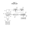
- Fig. 7 shows a basic device configuration and a signal transmission system disclosed in the above publication.
- a component "a” is gripped by fingers provided in a grip section G, and is assembled into a workpiece "b".
- a driving unit, such as a motor, 23 operates a robotic arm A.
- a control unit 24 inputs an operation signal and a position control signal for the robotic arm A.
- a calculation unit 25 calculates the relative displacement between the robotic arm A and the grip section G in six axial directions on the basis of detection signals from displacement sensors provided in a sensor unit 10.
- the calculation unit 25 is provided with an allowance setting unit 27 for setting an allowance that allows the component "a" to be properly assembled into the workpiece "b".
- a comparator 26 compares a displacement obtained from the calculation unit 25 and the set allowance, outputs the comparison result to the driving unit 23, and operates the robotic arm A so that the actual displacement is within the allowance.
- Fig. 8 is a detailed view of the sensor unit 10, and Fig. 9 is a cross-sectional plan view, taken along line IX-IX of Fig. 8 .
- the sensor unit 10 includes an arm-side plate 11 to be attached to the leading end of the robotic arm A, a grip-section-side plate 12 to be attached to the grip section G, and elastic members 13 that couple and support the plates 11 and 12.
- the sensor unit 10 also includes a displacement detection mechanism provided between the plates 11 and 12.
- the displacement detection mechanism includes a beam 14 extending from the arm-side plate 11 toward the grip-section-side plate 12 and having a cross-shaped leading end portion.
- the cross-shaped leading end portion of the beam 14 has X-direction displacement sensors 15 and 16 provided on opposite side faces parallel to the Y-axis, and Y-direction displacement sensors 17 and 18 provided on opposite side faces parallel to the X-axis.
- displacement sensors 19, 20, 21, and 22 are provided to face the grip-section-side plate 12 with a predetermined gap therebetween.
- the grip-section-side plate 12 is provided with protruding pieces 33, 34, 35, and 36 respectively facing the X-direction displacement sensors 15 and 16 and the Y-direction displacement sensors 17 and 18 with a predetermined gap therebetween.
- the robotic arm A is operated by the driving unit 23 according to a predetermined program input from the control unit 24 so that the component "a” gripped by the fingers of the grip section G is assembled (inserted) into the workpiece "b".
- the elastic members 13 are bent by the contact of the component "a” with the workpiece "b”, and a displacement of the grip section G relative to the robotic arm A is detected from the bending.
- the sensor unit 10 is connected between the robotic arm A and the grip section G in series.
- the sizes of the gripping device and the sensor unit 10 are reduced, it is difficult to ensure both a high force detection sensitivity of the sensor unit 10 and a high-speed operation, as follows.
- the size of the sensor unit 10 in the longitudinal direction of the arm can be reduced only by shortening the distance between the arm-side plate 11 and the grip-section-side plate 12, because the elastic members 13 are provided therebetween.
- the distance is shortened, the lengths of not only the elastic members 13 but also the beam 14 are reduced. Consequently, there is little distance between a support point of the beam 14 and the displacement sensors, and the amount of displacement detected by the detection sensors decreases.
- the detection sensitivity the ratio of the displacement amount detected by the displacement sensors to the applied force
- the detection sensitivity can be increased by replacing the elastic members 13 with more flexible members so as to reduce the rigidity of the elastic members 13.
- the rigidity of the elastic members 13 decreases, the grip section G easily wobbles with respect to the robotic arm A. For this reason, during driving of the robotic arm A, it takes much time to stably position the gripping device.
- the present invention provides a gripping device including a force sensor that achieves size reduction and speedup without decreasing detection sensitivity of a sensor unit.
- the present invention also provides a gripping device incorporating a force sensor that minimizes the influence of an excessive moment on a sensor unit because of an inertial force during operation of a robotic arm, and that realizes a shorter positioning time and a higher operation speed.
- the present invention further provides a gripping device including a force sensor that increases rigidity of elastic members, minimizes the difference in sensitivity between detection axes of the force sensor, and enables accurate force detection.
- the present invention in its first aspect provides a gripping device as specified in claims 1 to 10.
- the present invention in its second aspect provides a system for controlling a robotic arm as specified in claim 11.
- the first aspect of the present invention since a great distance can be ensured between the force sensor units and the deformation fulcrum of the elastic member even when the size is reduced, displacement of one force sensor relative to the other force sensor is increased. Thus, in spite of size reduction, a sufficient detection sensitivity can be ensured. Moreover, there is no need to decrease the rigidity of the elastic member to a degree such that the grip section wobbles relative to the robotic arm. Hence, it is possible to achieve a high force detection sensitivity of the force sensor units and high speed operation.
- the center of gravity of the grip section substantially coincides with the deformation fulcrum of the elastic member, it is possible to minimize the influence of the moment, which is produced by the inertial force due to the positional difference between the deformation fulcrum of the elastic member and the center of gravity of the grip section, on the force sensor units. Therefore, an excessive moment produced by the inertial force during operation of the force sensor units attached to the robotic arm does not have any influence. This shortens the time for stable positioning, and further increases the operation speed.
- the flexibility in designing rigidities of the displacement axes by combining the elastic materials increases, and desired rigidities can be designed while minimizing the difference in rigidity among the displacement axes (directions).
- desired rigidities can be designed while minimizing the difference in rigidity among the displacement axes (directions).
- the size of the force sensor units can be reduced while achieving both a high detection sensitivity of the force sensor units and restriction of the increase in stable positioning time during high speed movement of the robotic arm.
- the sensitivity difference among the detection axes of the force sensors can be reduced.
- the rigidity of the elastic member can be increased, and the sensitivity difference among the detection axes of the force sensors can be reduced while increasing the rigidity of the elastic member. This achieves accurate force detection.
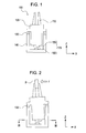
- Fig. 1 is a schematic structural view of an embodiment of the present invention.
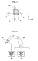
- Fig. 2 shows a state in which a component is gripped by a grip section and a force is applied during assembly in the embodiment.
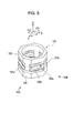
- Fig. 3 is an enlarged cross-sectional plan view of a displacement detection unit in the embodiment, taken along line III-III of Fig. 2 .
- Fig. 4 shows a state in which a gripping device of the embodiment is mounted to a robotic arm.
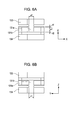
- Fig. 5 shows an elastic member in the embodiment.
- Figs. 6A and 6B are views, respectively, on arrow VIA and arrow VIB of Fig. 5 , respectively.
- Fig. 7 is a schematic structural view of a gripping device of the related art.
- Fig. 8 is an enlarged view of a displacement detection unit in the gripping device of the related art.
- Fig. 9 is a cross-sectional plan view of the displacement detection unit, taken along line IX-IX of Fig. 8 .
- the embodiment of the present invention provides a small gripping device including a force sensor.
- the gripping device grips and assembles a component of a small product, such as a camera, while controlling the force at a high speed.
- a gripping device 100 includes detachable fingers 110 for gripping a component, and a driving mechanism 120, such as a motor, for driving the fingers 110.
- a plurality of fingers 110 and the driving mechanism 120 are connected to form a grip section.
- the gripping device 100 also includes an elastic member 130 that is elastically deformed by a force received by the grip section, force sensor units 170 for detecting an assembly reaction force produced during gripping and assembly of the component, and a gripping device housing 140 in which a part of the driving mechanism 120 is stored.
- a straight line linking the midpoint between the two fingers 110 and the centers of the force sensor units 170 is referred to as a Z-axis.
- an upward direction is a +Z-direction
- a rightward direction is a +X-direction
- a direction toward the back side of the plane of the figure is a +Y-direction.
- the number of fingers 110, the number of joints, and elasticity are selected in accordance with the component and the assembly operation, and the grip section can have various shapes.
- fingers of various shapes may be interchangeably attached to the driving mechanism 120 without changing the driving mechanism 120.
- a coupling portion to the driving mechanism 120 is commonly used so that various types of fingers can be attached.
- the driving mechanism 120 is a mechanism that is driven in connection with the fingers 110, and includes a unit of mechanical members, such as gears and links, an actuator, etc.
- the driving mechanism 120 is fixed to the gripping device housing 140 with the elastic member 130 being disposed therebetween in a manner such that the attitude thereof is changeable.
- the driving mechanism 120 connected to the fingers 110 is supported by the gripping device housing 140 via the elastic member 130, it can change its attitude relative to the gripping device housing 140 by the load applied to the fingers 110 or the driving mechanism 120.
- a pair of displacement type force sensor units 170 are respectively provided on an end portion of the driving mechanism 120 opposite the fingers 110 and a wall surface of the gripping device housing 140 facing the end portion.
- the force sensor units 170 include a displacement output element 150 provided on the driving mechanism 120, and a displacement detection element 160 provided on the opposing gripping device housing 140.
- the driving mechanism 120 may further include a member on which the displacement output element 150 is mounted.
- vibration of the driving mechanism 120 such as a motor
- the driving mechanism 120 attenuates while propagating to the members.
- the advantage of being able to prevent noise contamination of signals detected by the force sensor units 170 can be expected.
- F represents an operating force in an XY plane of an assembly reaction force applied to the fingers 110 when the component P is gripped and assembled.
- the driving mechanism 120 is displaced relative to the gripping device housing 140 on the elastic member 130, as shown in Fig. 2 .
- the force sensor units 170 are defined by a mechanism formed by a combination of a Hall element for detecting the displacement of the driving mechanism 120 relative to the gripping device housing 140, and a permanent magnet serving as a magnetic-field generating source.
- the mechanism is not particularly limited to the above-described magnetic displacement sensor as long as it can detect the displacement.
- a calculation unit calculates an operating force F from the displacement amount detected by the force sensor units 170.
- Fig. 3 is a cross-sectional plan view, taken along line III-III of Fig. 2 .
- the displacement output element 150 is a permanent magnet and the displacement detection element 160 includes displacement detection elements 161, 162, 163, and 164 serving as Hall elements, as shown in Fig. 3 , when the distances between the permanent magnet and the Hall elements change, the density of magnetic flux flowing into the Hall elements changes, whereby the displacement amount of the driving mechanism 120 relative to the gripping device housing 140 can be detected.
- the displacement detection elements 161, 162, 163, and 164 (four in total) at +X-, -X-, +Y-, and -Y-positions on the gripping device housing 140, respectively, not only the displacement amount, but also the displacement direction can be detected.
- the displacement output element 150 displaces in the +X-direction and the +Y-direction.
- Fig. 4 schematically shows the above-described gripping device 100 attached to a robotic arm 200 and control units for the robotic arm 200 and the gripping device 100.
- a gripping-device control unit 180 is connected to the gripping device 100.
- the gripping-device control unit 180 controls the operation of the gripping device 100, and also performs calculation for converting a displacement signal detected by the force sensor units 170 into force.
- a robotic-arm control unit 210 is connected to the robotic arm 200.
- the robotic-arm control unit 210 controls the operation of the robotic arm 200, and receives information about the force applied to the fingers 110 of the gripping device 100 from the grip-device control unit 180 so as to reflect the information in the operation of the robotic arm 200.
- the elastic member 130 is located to support the wall surface of the driving mechanism 120. More specifically, the elastic member 130 is located to support a portion of the wall surface at or near the center of gravity of the grip section.
- the centre of gravity of the grip section can be adjusted (e.g. to give a low or high centre of gravity to the grip section) by specifically designing the component(s) of the driving mechanism (e.g. motor) to give a desire centre of gravity.
- the centre of gravity of the grip section may also be adjusted by changing the position of the elastic member 130 relative to the housing 140 and the driving mechanism 120.
- the inertial force acting during operation of the robotic arm 200 is mainly applied to the driving mechanism 120 and the fingers 110 connected via the elastic member 130.
- the elastic member 130 may be provided between a position at or near the center of gravity of the grip section and the fingers 110, e.g. at or near the position where the fingers 110 are coupled to the driving mechanism 120.
- the distance from the fulcrum of attitude deformation to the force sensor units 170 can be further increased.
- the distance between the elastic member 130 and the force sensor units 170 is greater than or equal to 40% of the distance L. Therefore, even when the same operating force F is applied to the fingers 110, the displacement amount of the displacement output element 150 and the displacement detection element 160 can be increased greatly. This allows more accurate force sensing.
- Displacement information detected by the force sensor units 170 is transmitted to the gripping-device control unit 180, and the volume and direction of the operating force F applied to the fingers 110 are calculated by the calculator in the gripping-device control unit 180.
- the calculation result is then transmitted to the robotic-arm control unit 210.
- the robotic-arm control unit 210 performs assembly while controlling the operation of the robotic arm 200 so that the applied operating force F is within a predetermined range in order to prevent the component P and the robotic arm 200 from damage.
- the elastic member 130 is provided between the fingers 110 and the force sensor units 170, as described above, even when the size of the force sensor units 170 is reduced, a long distance can be ensured between the force sensor units 170 and the elastic member 130 serving as the deformation fulcrum of the driving mechanism 120.
- the elastic member 130 serving as the deformation fulcrum of the driving mechanism 120 relative to the gripping device housing 140 is provided between a position near the center of gravity of the grip section and the fingers 110. Since this increases deformation at the force sensor units 170, a sufficient detection sensitivity can be ensured. Further, since the sufficient detection sensitivity is ensured, there is no need to decrease the rigidity of the elastic member 130. Hence, the grip section will not wobble relative to the gripping device housing 140 during high-speed movement of the robotic arm 200, and it is possible to achieve both size reduction and speedup.
- the center of gravity of the grip section coincides with the deformation fulcrum of the elastic member 130, it is possible to minimize the influence of the moment, which is produced by the positional difference between the deformation fulcrum of the elastic member 130 and the center of gravity of the grip section, on the force sensor units 170. With this structure, it is particularly possible to shorten the time taken to stably position the gripping device during high-speed movement of the robotic arm 200 and to more easily respond to high speed operation.
- the elastic member 130 may be formed by a one-piece support member shaped like a ring or a band of rubber or the like, or a plurality of rubber members that support the wall surface of the driving mechanism 120 at a plurality of fulcrums, it may be the following structure formed by leaf springs in order to adjust the difference in sensitivity among the detection axes, that is, X-, Y-, and Z-axes, of the force sensor.
- Fig. 5 shows a specific structure of the elastic member 130 provided when the force sensor has three detection axes, that is, X-, Y-, and Z-axes.
- Fig. 6A is a view on arrow VIA of Fig. 5
- Fig. 6B is a view on arrow VIB of Fig. 5 .
- an upper member 133 fixed to the driving mechanism 120 is provided on the +Z-side
- a lower member 134 fixed to the gripping device housing 140 is provided on the -Z-side.
- a leaf spring 132 includes two leaf springs stacked in the Z-direction, namely, an upper leaf spring 132a and a lower leaf spring 132b.
- Two leaf-spring support members 131a spaced 180 degrees apart are combined with two-leaf spring support members 131b spaced 180 degrees apart.
- the leaf-spring support members 131a and 131b support the leaf spring 132, and are respectively fixed to the upper member 133 and the lower member 134.
- the X- and Y-axes of detection of the force sensor respectively correspond to a rotation axis ⁇ y about the Y-axis and a rotation axis ⁇ x about the X-axis in the elastic member 130. While the displacements along the ⁇ x-axis and the ⁇ y-axis are increased to be larger at the sensor unit than at the deformation fulcrum of the elastic member 130, the displacement along the Z-axis is not increased because the displacement direction coincides with the displacement detection direction of the sensor unit. Accordingly, detection sensitivity of the sensor unit differs between when the operating force F acts in the X-direction and when the operating force F acts in the Z-direction in Fig. 2 .
- the rigidities in the Z-, ⁇ x-, and ⁇ y-axis directions can be adjusted to desired values.
- cross-sectional areas of the leaf-spring support members 131a and 131b are sufficiently larger than the cross-sectional areas of the leaf springs 132a and 132b, and the displacement amount of the leaf-spring support members is sufficiently smaller than the displacement amount of the leaf springs.
- the above-described embodiment is just exemplary, and does not limit the structures. Any component can be used as long as it can be gripped. While the two fingers 110 are shown in the figures, the number of fingers 110 is not limited to two as long as the fingers 110 can grip the component.
- the driving mechanism 120 may be formed by any driving mechanism that allows gripping with the fingers 110, and may include any driving source (electromagnetic type or an air compression type) and any mechanism portion (e.g., gears, links).
- the elastic member has three detection axes in the embodiment, the number of axes is not limited. The shape, number, and positions of the leaf springs and leaf-spring support members may be changed in accordance with the required number of axes.
- any sensors can be used as long as they can detect the relative displacement (e.g., a laser displacement gauge or an eddy-current sensor). Further, detection along six axes (X, Y, Z, ⁇ x, ⁇ y, and ⁇ z axes, ⁇ represents the rotation axes about the X-, Y-, and Z-axes) can be realized by changing the number and positions of the detection elements.
- the gripping device including the force sensor according to the present invention can realize both a smaller size and a higher detection sensitivity than in the related art, and can grip and assemble small components at high speed under force control.
- the present invention is applicable to a high-speed small gripping device for automated assembly with an industrial robot.
- An embodiment of the invention can provide a gripping device that grips a component, the gripping device comprising: a grip section including a plurality of fingers configured to grip the component, and a driving mechanism connected to the fingers so as to drive the fingers; a housing configured to elastically support the driving mechanism with an elastic member being disposed therebetween, the housing containing a part of the driving mechanism; and force sensor units respectively provided on an end portion of the driving mechanism opposite the fingers and at a position on the housing facing the end portion, wherein the elastic member is provided between a position near the center of gravity of the grip section and the fingers.
Abstract
Description
- The present invention relates to a gripping device attached to, for example, a leading end of an arm of an industrial robot so as to grip and assemble various components. More particularly, the present invention relates to a gripping device that detects the assembly reaction force during assembly of components and performs assembly while controlling the assembly force, and that is applicable to automated assembly with an industrial robot.
- In recent years, there is an increasing demand for automated manufacturing of products having a complicated structure, for example, cameras. For such products, it is necessary to perform high-speed and accurate assembly with a small industrial robot under fine force control.
- Japanese Patent Laid-Open No.
61-241083 -
Fig. 7 shows a basic device configuration and a signal transmission system disclosed in the above publication. Referring toFig. 7 , a component "a" is gripped by fingers provided in a grip section G, and is assembled into a workpiece "b". A driving unit, such as a motor, 23 operates a robotic arm A. To thedriving unit 23, acontrol unit 24 inputs an operation signal and a position control signal for the robotic arm A. - A
calculation unit 25 calculates the relative displacement between the robotic arm A and the grip section G in six axial directions on the basis of detection signals from displacement sensors provided in asensor unit 10.
Thecalculation unit 25 is provided with anallowance setting unit 27 for setting an allowance that allows the component "a" to be properly assembled into the workpiece "b". Acomparator 26 compares a displacement obtained from thecalculation unit 25 and the set allowance, outputs the comparison result to thedriving unit 23, and operates the robotic arm A so that the actual displacement is within the allowance. -
Fig. 8 is a detailed view of thesensor unit 10, andFig. 9 is a cross-sectional plan view, taken along line IX-IX ofFig. 8 . Referring toFig. 8 , thesensor unit 10 includes an arm-side plate 11 to be attached to the leading end of the robotic arm A, a grip-section-side plate 12 to be attached to the grip section G, andelastic members 13 that couple and support theplates sensor unit 10 also includes a displacement detection mechanism provided between theplates beam 14 extending from the arm-side plate 11 toward the grip-section-side plate 12 and having a cross-shaped leading end portion. - As shown in
Fig. 9 , the cross-shaped leading end portion of thebeam 14 hasX-direction displacement sensors direction displacement sensors side plate 12,displacement sensors side plate 12 with a predetermined gap therebetween. The grip-section-side plate 12 is provided withprotruding pieces X-direction displacement sensors direction displacement sensors - With these structures, the robotic arm A is operated by the
driving unit 23 according to a predetermined program input from thecontrol unit 24 so that the component "a" gripped by the fingers of the grip section G is assembled (inserted) into the workpiece "b". In this case, when there is a relative positional error between the component "a" and the workpiece "b", theelastic members 13 are bent by the contact of the component "a" with the workpiece "b", and a displacement of the grip section G relative to the robotic arm A is detected from the bending. By performing the inserting operation in a state in which the relative displacement is within a predetermined allowance, proper assembly is realized while preventing the component "a", the workpiece "b", and the gripping device from damage. - In the gripping device of the above related art, however, the
sensor unit 10 is connected between the robotic arm A and the grip section G in series. When the sizes of the gripping device and thesensor unit 10 are reduced, it is difficult to ensure both a high force detection sensitivity of thesensor unit 10 and a high-speed operation, as follows. - The size of the
sensor unit 10 in the longitudinal direction of the arm can be reduced only by shortening the distance between the arm-side plate 11 and the grip-section-side plate 12, because theelastic members 13 are provided therebetween. However, when the distance is shortened, the lengths of not only theelastic members 13 but also thebeam 14 are reduced. Consequently, there is little distance between a support point of thebeam 14 and the displacement sensors, and the amount of displacement detected by the detection sensors decreases. Hence, the detection sensitivity (the ratio of the displacement amount detected by the displacement sensors to the applied force) decreases. - On the other hand, the detection sensitivity can be increased by replacing the
elastic members 13 with more flexible members so as to reduce the rigidity of theelastic members 13. Unfortunately, when the rigidity of theelastic members 13 decreases, the grip section G easily wobbles with respect to the robotic arm A. For this reason, during driving of the robotic arm A, it takes much time to stably position the gripping device. - This point will be described in detail. In the related art shown in
Fig. 7 , since thesensor unit 10 is connected in series between the robotic arm A and the grip section G, deformation fulcrums of theelastic members 13 in thesensor unit 10 are away from the center of gravity of the grip section G. Consequently, a moment produced by an inertial force due to the positional difference between the deformation fulcrums of theelastic members 13 and the center of gravity of the grip section G has a great influence on the grip section G during driving of the robotic arm A, and it also takes much time to stably position thesensor unit 10 connected to the grip section G. The time necessary for stable positioning increases as the rigidity of theelastic members 13 decreases. - When the gripping device of the related art is driven at a high speed in order to enhance the working efficiency, the above-described moment increases as the speed increases, and the time necessary for stable positioning increases. Although the rigidity of the elastic members needs to be increased in order to shorten the time for stable positioning, the increase in rigidity reduces detection sensitivity of the sensor unit, and makes it difficult to accurately detect the force.
- In this way, in the gripping device of the related art, when the size of the sensor unit is reduced in the longitudinal direction of the robotic arm, it is difficult to ensure both a high detection sensitivity and a high operation speed.
- The present invention provides a gripping device including a force sensor that achieves size reduction and speedup without decreasing detection sensitivity of a sensor unit.
- The present invention also provides a gripping device incorporating a force sensor that minimizes the influence of an excessive moment on a sensor unit because of an inertial force during operation of a robotic arm, and that realizes a shorter positioning time and a higher operation speed.
- The present invention further provides a gripping device including a force sensor that increases rigidity of elastic members, minimizes the difference in sensitivity between detection axes of the force sensor, and enables accurate force detection.
- The present invention in its first aspect provides a gripping device as specified in
claims 1 to 10. - The present invention in its second aspect provides a system for controlling a robotic arm as specified in
claim 11. - According to the first aspect of the present invention, since a great distance can be ensured between the force sensor units and the deformation fulcrum of the elastic member even when the size is reduced, displacement of one force sensor relative to the other force sensor is increased. Thus, in spite of size reduction, a sufficient detection sensitivity can be ensured. Moreover, there is no need to decrease the rigidity of the elastic member to a degree such that the grip section wobbles relative to the robotic arm. Hence, it is possible to achieve a high force detection sensitivity of the force sensor units and high speed operation.
- Further, since the center of gravity of the grip section substantially coincides with the deformation fulcrum of the elastic member, it is possible to minimize the influence of the moment, which is produced by the inertial force due to the positional difference between the deformation fulcrum of the elastic member and the center of gravity of the grip section, on the force sensor units. Therefore, an excessive moment produced by the inertial force during operation of the force sensor units attached to the robotic arm does not have any influence. This shortens the time for stable positioning, and further increases the operation speed.
- According to the first aspect of the present invention, the flexibility in designing rigidities of the displacement axes by combining the elastic materials increases, and desired rigidities can be designed while minimizing the difference in rigidity among the displacement axes (directions). By forming the elastic materials by leaf springs, the rigidity of the elastic member can be increased. Since the sensitivity difference among the detection axes of the force sensors can thus be reduced while increasing the rigidity of the elastic member, accurate force detection is possible.
- According to the first aspect of the present invention, the size of the force sensor units can be reduced while achieving both a high detection sensitivity of the force sensor units and restriction of the increase in stable positioning time during high speed movement of the robotic arm.
- Further, it is possible to minimize the influence of the moment, which is produced by the inertial force due to the positional difference between the deformation fulcrum of the elastic member and the center of gravity of the grip section, on the force sensor units. Therefore, in particular, the time necessary for stable positioning can be shortened and speedup can be realized.
- In addition, the sensitivity difference among the detection axes of the force sensors can be reduced. Further, when the elastic materials are formed by leaf springs, the rigidity of the elastic member can be increased, and the sensitivity difference among the detection axes of the force sensors can be reduced while increasing the rigidity of the elastic member. This achieves accurate force detection.
- Further features of the present invention will become apparent from the following description of exemplary embodiments with reference to the attached drawings.
-
Fig. 1 is a schematic structural view of an embodiment of the present invention. -
Fig. 2 shows a state in which a component is gripped by a grip section and a force is applied during assembly in the embodiment. -
Fig. 3 is an enlarged cross-sectional plan view of a displacement detection unit in the embodiment, taken along line III-III ofFig. 2 . -
Fig. 4 shows a state in which a gripping device of the embodiment is mounted to a robotic arm. -
Fig. 5 shows an elastic member in the embodiment. -
Figs. 6A and 6B are views, respectively, on arrow VIA and arrow VIB ofFig. 5 , respectively. -
Fig. 7 is a schematic structural view of a gripping device of the related art. -
Fig. 8 is an enlarged view of a displacement detection unit in the gripping device of the related art. -
Fig. 9 is a cross-sectional plan view of the displacement detection unit, taken along line IX-IX ofFig. 8 . - A basic configuration of an embodiment of the present invention will be described below with reference to
Figs. 1 to 4 . The embodiment of the present invention provides a small gripping device including a force sensor. The gripping device grips and assembles a component of a small product, such as a camera, while controlling the force at a high speed. - Referring to
Fig. 1 , agripping device 100 includesdetachable fingers 110 for gripping a component, and adriving mechanism 120, such as a motor, for driving thefingers 110. A plurality offingers 110 and thedriving mechanism 120 are connected to form a grip section. - The
gripping device 100 also includes anelastic member 130 that is elastically deformed by a force received by the grip section,force sensor units 170 for detecting an assembly reaction force produced during gripping and assembly of the component, and agripping device housing 140 in which a part of thedriving mechanism 120 is stored. A straight line linking the midpoint between the twofingers 110 and the centers of theforce sensor units 170 is referred to as a Z-axis. InFig. 1 , an upward direction is a +Z-direction, a rightward direction is a +X-direction, and a direction toward the back side of the plane of the figure is a +Y-direction. - The number of
fingers 110, the number of joints, and elasticity are selected in accordance with the component and the assembly operation, and the grip section can have various shapes. Alternatively, fingers of various shapes may be interchangeably attached to thedriving mechanism 120 without changing thedriving mechanism 120. In this case, preferably, a coupling portion to thedriving mechanism 120 is commonly used so that various types of fingers can be attached. - The
driving mechanism 120 is a mechanism that is driven in connection with thefingers 110, and includes a unit of mechanical members, such as gears and links, an actuator, etc. Thedriving mechanism 120 is fixed to thegripping device housing 140 with theelastic member 130 being disposed therebetween in a manner such that the attitude thereof is changeable. In short, since thedriving mechanism 120 connected to thefingers 110 is supported by thegripping device housing 140 via theelastic member 130, it can change its attitude relative to thegripping device housing 140 by the load applied to thefingers 110 or thedriving mechanism 120. - A pair of displacement type
force sensor units 170 are respectively provided on an end portion of thedriving mechanism 120 opposite thefingers 110 and a wall surface of thegripping device housing 140 facing the end portion. Theforce sensor units 170 include adisplacement output element 150 provided on thedriving mechanism 120, and adisplacement detection element 160 provided on the opposinggripping device housing 140. To adjust the distance between thedisplacement output element 150 and thedisplacement detection element 160, thedriving mechanism 120 may further include a member on which thedisplacement output element 150 is mounted. - With the above-described configuration, vibration of the
driving mechanism 120, such as a motor, attenuates while propagating to the members. Hence, the advantage of being able to prevent noise contamination of signals detected by theforce sensor units 170 can be expected. - Referring to
Figs. 1 and 2 , a description will be given below of a state in which thegripping device 100 grips and assembles a component P. InFig. 2 , F represents an operating force in an XY plane of an assembly reaction force applied to thefingers 110 when the component P is gripped and assembled. Thedriving mechanism 120 is displaced relative to thegripping device housing 140 on theelastic member 130, as shown inFig. 2 . - The
force sensor units 170 are defined by a mechanism formed by a combination of a Hall element for detecting the displacement of thedriving mechanism 120 relative to thegripping device housing 140, and a permanent magnet serving as a magnetic-field generating source. The mechanism is not particularly limited to the above-described magnetic displacement sensor as long as it can detect the displacement. - A calculation unit (not shown) calculates an operating force F from the displacement amount detected by the
force sensor units 170.Fig. 3 is a cross-sectional plan view, taken along line III-III ofFig. 2 . For example, in a case in which thedisplacement output element 150 is a permanent magnet and thedisplacement detection element 160 includesdisplacement detection elements Fig. 3 , when the distances between the permanent magnet and the Hall elements change, the density of magnetic flux flowing into the Hall elements changes, whereby the displacement amount of thedriving mechanism 120 relative to thegripping device housing 140 can be detected. - By placing the
displacement detection elements gripping device housing 140, respectively, not only the displacement amount, but also the displacement direction can be detected. When it is assumed that the operating force F during assembly acts in the -X-direction and the -Y-direction in the XY plane, thedisplacement output element 150 displaces in the +X-direction and the +Y-direction. Therefore, outputs from thedisplacement detection elements displacement output elements -
Fig. 4 schematically shows the above-describedgripping device 100 attached to arobotic arm 200 and control units for therobotic arm 200 and thegripping device 100. A gripping-device control unit 180 is connected to thegripping device 100. The gripping-device control unit 180 controls the operation of thegripping device 100, and also performs calculation for converting a displacement signal detected by theforce sensor units 170 into force. - A robotic-
arm control unit 210 is connected to therobotic arm 200. The robotic-arm control unit 210 controls the operation of therobotic arm 200, and receives information about the force applied to thefingers 110 of thegripping device 100 from the grip-device control unit 180 so as to reflect the information in the operation of therobotic arm 200. - The
elastic member 130 is located to support the wall surface of thedriving mechanism 120. More specifically, theelastic member 130 is located to support a portion of the wall surface at or near the center of gravity of the grip section. The centre of gravity of the grip section can be adjusted (e.g. to give a low or high centre of gravity to the grip section) by specifically designing the component(s) of the driving mechanism (e.g. motor) to give a desire centre of gravity. The centre of gravity of the grip section may also be adjusted by changing the position of theelastic member 130 relative to thehousing 140 and thedriving mechanism 120. The inertial force acting during operation of therobotic arm 200 is mainly applied to thedriving mechanism 120 and thefingers 110 connected via theelastic member 130. - As long as the time taken to stably position the grip section relative to the
gripping device housing 140 does not extremely increase, theelastic member 130 may be provided between a position at or near the center of gravity of the grip section and thefingers 110, e.g. at or near the position where thefingers 110 are coupled to thedriving mechanism 120. In this case, the distance from the fulcrum of attitude deformation to theforce sensor units 170 can be further increased. For example, when the total distance of the grip section in the longitudinal direction is a distance L, the distance between theelastic member 130 and theforce sensor units 170 is greater than or equal to 40% of the distance L. Therefore, even when the same operating force F is applied to thefingers 110, the displacement amount of thedisplacement output element 150 and thedisplacement detection element 160 can be increased greatly. This allows more accurate force sensing. - A description will now be given of a series of assembly operations performed under force control. When the gripped component P comes into contact with another component to which the component P is to be assembled, the assembly operating force F is received by the
fingers 110 attached to thedriving mechanism 120, and theelastic member 130 is thereby bent. The operating force F is detected by theforce sensor units 170, as described above. - Displacement information detected by the
force sensor units 170 is transmitted to the gripping-device control unit 180, and the volume and direction of the operating force F applied to thefingers 110 are calculated by the calculator in the gripping-device control unit 180. The calculation result is then transmitted to the robotic-arm control unit 210. On the basis of the transmitted information about the operating force F, the robotic-arm control unit 210 performs assembly while controlling the operation of therobotic arm 200 so that the applied operating force F is within a predetermined range in order to prevent the component P and therobotic arm 200 from damage. - Since the
elastic member 130 is provided between thefingers 110 and theforce sensor units 170, as described above, even when the size of theforce sensor units 170 is reduced, a long distance can be ensured between theforce sensor units 170 and theelastic member 130 serving as the deformation fulcrum of thedriving mechanism 120. - In the robot hand including the force sensor of the related art shown in
Fig. 8 , when the length of theelastic members 13 is reduced, the length of thebeam 14 also needs to be reduced. For this reason, the distance from the joint portion with theplate 11 serving as the displacement fulcrum of thebeam 14 to the leading end of thebeam 14 is forced to be shortened. In this case, since the displacement of thedisplacement sensor 15 due to the operating force F decreases, the detection sensitivity decreases, as described above. - In the embodiment of the present invention, the
elastic member 130 serving as the deformation fulcrum of thedriving mechanism 120 relative to thegripping device housing 140 is provided between a position near the center of gravity of the grip section and thefingers 110. Since this increases deformation at theforce sensor units 170, a sufficient detection sensitivity can be ensured. Further, since the sufficient detection sensitivity is ensured, there is no need to decrease the rigidity of theelastic member 130. Hence, the grip section will not wobble relative to thegripping device housing 140 during high-speed movement of therobotic arm 200, and it is possible to achieve both size reduction and speedup. - In addition, since the center of gravity of the grip section coincides with the deformation fulcrum of the
elastic member 130, it is possible to minimize the influence of the moment, which is produced by the positional difference between the deformation fulcrum of theelastic member 130 and the center of gravity of the grip section, on theforce sensor units 170. With this structure, it is particularly possible to shorten the time taken to stably position the gripping device during high-speed movement of therobotic arm 200 and to more easily respond to high speed operation. - Examples of the
elastic member 130 will be described below. While theelastic member 130 may be formed by a one-piece support member shaped like a ring or a band of rubber or the like, or a plurality of rubber members that support the wall surface of thedriving mechanism 120 at a plurality of fulcrums, it may be the following structure formed by leaf springs in order to adjust the difference in sensitivity among the detection axes, that is, X-, Y-, and Z-axes, of the force sensor. -
Fig. 5 shows a specific structure of theelastic member 130 provided when the force sensor has three detection axes, that is, X-, Y-, and Z-axes.Fig. 6A is a view on arrow VIA ofFig. 5 , andFig. 6B is a view on arrow VIB ofFig. 5 . - Referring to
Fig. 5 , anupper member 133 fixed to thedriving mechanism 120 is provided on the +Z-side, and alower member 134 fixed to thegripping device housing 140 is provided on the -Z-side. A leaf spring 132 includes two leaf springs stacked in the Z-direction, namely, anupper leaf spring 132a and alower leaf spring 132b. Two leaf-spring support members 131a spaced 180 degrees apart are combined with two-leafspring support members 131b spaced 180 degrees apart. The leaf-spring support members upper member 133 and thelower member 134. - When an operating force F is applied to the
fingers 110, the leaf spring 132 bends, and theelastic member 130 thereby deforms elastically. The X- and Y-axes of detection of the force sensor respectively correspond to a rotation axis ωy about the Y-axis and a rotation axis ωx about the X-axis in theelastic member 130. While the displacements along the ωx-axis and the ωy-axis are increased to be larger at the sensor unit than at the deformation fulcrum of theelastic member 130, the displacement along the Z-axis is not increased because the displacement direction coincides with the displacement detection direction of the sensor unit. Accordingly, detection sensitivity of the sensor unit differs between when the operating force F acts in the X-direction and when the operating force F acts in the Z-direction inFig. 2 . - It is impossible to adjust this sensitivity difference between the Z-axis, and the ωx-axis and the ωy-axis by merely selecting the material of the
elastic member 130. By stacking a plurality of leaf springs (elastic materials), as in the embodiment, the rigidity in the Z-axis direction in which displacement is not increased can be adjusted while maintaining the rigidities in the ωx-and ωy-axis directions. By adjusting thicknesses t1 and t2 of the leaf springs, a distance s1 between the leaf springs, and widths u1 and v1 of the leaf-spring support members, as shown inFigs. 6A and 6B , the rigidities in the Z-, ωx-, and ωy-axis directions can be adjusted to desired values. In this case, cross-sectional areas of the leaf-spring support members leaf springs - The above-described embodiment is just exemplary, and does not limit the structures. Any component can be used as long as it can be gripped. While the two
fingers 110 are shown in the figures, the number offingers 110 is not limited to two as long as thefingers 110 can grip the component. For example, thedriving mechanism 120 may be formed by any driving mechanism that allows gripping with thefingers 110, and may include any driving source (electromagnetic type or an air compression type) and any mechanism portion (e.g., gears, links). While the elastic member has three detection axes in the embodiment, the number of axes is not limited. The shape, number, and positions of the leaf springs and leaf-spring support members may be changed in accordance with the required number of axes. While the force sensor unit includes the Hall elements in the embodiment, any sensors can be used as long as they can detect the relative displacement (e.g., a laser displacement gauge or an eddy-current sensor).
Further, detection along six axes (X, Y, Z, θx, θy, and θz axes, θ represents the rotation axes about the X-, Y-, and Z-axes) can be realized by changing the number and positions of the detection elements. - As described above, the gripping device including the force sensor according to the present invention can realize both a smaller size and a higher detection sensitivity than in the related art, and can grip and assemble small components at high speed under force control.
- The present invention is applicable to a high-speed small gripping device for automated assembly with an industrial robot.
- An embodiment of the invention can provide a gripping device that grips a component, the gripping device comprising: a grip section including a plurality of fingers configured to grip the component, and a driving mechanism connected to the fingers so as to drive the fingers; a housing configured to elastically support the driving mechanism with an elastic member being disposed therebetween, the housing containing a part of the driving mechanism; and force sensor units respectively provided on an end portion of the driving mechanism opposite the fingers and at a position on the housing facing the end portion, wherein the elastic member is provided between a position near the center of gravity of the grip section and the fingers.
- While the present invention has been described with reference to exemplary embodiments, it is to be understood that the invention is not limited to the disclosed exemplary embodiments. The scope of the following claims is to be accorded the broadest interpretation so as to encompass all modifications and equivalent structures and functions.
Claims (11)
- A gripping device (100) for gripping a component, the gripping device (100) comprising:gripping means having at least one gripping element (110) configured to grip the component, and a driving mechanism (120) connected to the gripping element (110) for driving the gripping element (110);a housing (140);an elastic member (130) disposed between the housing (140) and the driving mechanism (120); andforce sensor means (170) provided on an end portion of the driving mechanism (120) opposite the gripping element (110) and at a position on the housing (140) facing the end portion,wherein the elastic member (130) is provided between a first position at or near the center of gravity of the gripping means, and a second position at or near said gripping element (110).
- The gripping device according to claim 1, wherein the elastic member (130) is configured to be provided at or near the center of gravity of the gripping means.
- The gripping device according to claim 1 or claim 2, wherein the total distance of the gripping means in the longitudinal direction is a distance L and wherein the distance between the elastic member (130) and the force sensor means (170) is greater than or equal to 40% of the distance L.
- The gripping device according to any preceding claim, wherein the elastic member (130) is configured to serve as a deformation fulcrum of the gripping means relative to the housing (140).
- The gripping device according to claim 4, wherein the gripping means and the elastic member (130) are configured such that the centre of gravity of the gripping means substantially coincides with the deformation fulcrum of the elastic member (130).
- The gripping device according to any preceding claim, wherein the elastic member (130) is formed by a structure in which a plurality of leaf springs (132) are stacked.
- The gripping device according to any preceding claim, wherein the elastic member (130) is formed by a rubber shaped like a ring or a band.
- The gripping device according to any preceding claim, wherein the force sensor means (170) comprises at least one Hall element (160) for detecting displacement of the driving mechanism (120) relative to the housing (140), and a magnet (150) configured to serve as a magnetic-field generating source.
- The gripping device according to any one of claim 2 to 8, wherein the driving mechanism (120) comprises a coupling portion for coupling gripping elements (110) of different types.
- The gripping device according to any preceding claim, wherein the housing (140) is configured to contain a part of the driving mechanism (120) and wherein the gripping element comprises at least one finger.
- A system for controlling a robotic arm (200) comprising:the gripping device (100) of any preceding claim, wherein the gripping device (100) is configured for attachment to the robotic arm (200); andcontrol means (180, 210) for controlling the robotic arm (200) and the gripping device (100).
Applications Claiming Priority (2)
| Application Number | Priority Date | Filing Date | Title |
|---|---|---|---|
| JP2008279872 | 2008-10-30 | ||
| JP2009229652A JP2010131743A (en) | 2008-10-30 | 2009-10-01 | Gripping device including force sensor |
Publications (2)
| Publication Number | Publication Date |
|---|---|
| EP2181814A1 true EP2181814A1 (en) | 2010-05-05 |
| EP2181814B1 EP2181814B1 (en) | 2012-06-06 |
Family
ID=41528673
Family Applications (1)
| Application Number | Title | Priority Date | Filing Date |
|---|---|---|---|
| EP09174701A Not-in-force EP2181814B1 (en) | 2008-10-30 | 2009-10-30 | Gripping device and system including the same |
Country Status (4)
| Country | Link |
|---|---|
| US (1) | US8182197B2 (en) |
| EP (1) | EP2181814B1 (en) |
| JP (1) | JP2010131743A (en) |
| CN (1) | CN101722519B (en) |
Cited By (12)
| Publication number | Priority date | Publication date | Assignee | Title |
|---|---|---|---|---|
| WO2011145713A1 (en) * | 2010-05-20 | 2011-11-24 | Canon Kabushiki Kaisha | Force control robot |
| WO2015061837A1 (en) | 2013-10-31 | 2015-05-07 | Anca Pty Ltd | Tool gripper arrangement |
| WO2017035016A1 (en) * | 2015-08-26 | 2017-03-02 | Berkshire Grey Inc. | Systems and methods for providing contact detection in an articulated arm |
| EP3220148A1 (en) * | 2016-03-17 | 2017-09-20 | Siemens Healthcare Diagnostics Products GmbH | Method for monitoring the transport of liquid containers in an automatic analyzer |
| US10011020B2 (en) | 2016-01-08 | 2018-07-03 | Berkshire Grey, Inc. | Systems and methods for acquiring and moving objects |
| US10350755B2 (en) | 2016-02-08 | 2019-07-16 | Berkshire Grey, Inc. | Systems and methods for providing processing of a variety of objects employing motion planning |
| US10639787B2 (en) | 2017-03-06 | 2020-05-05 | Berkshire Grey, Inc. | Systems and methods for efficiently moving a variety of objects |
| US10647002B2 (en) | 2015-09-01 | 2020-05-12 | Berkshire Grey, Inc. | Systems and methods for providing dynamic robotic control systems |
| US10723019B2 (en) | 2017-08-02 | 2020-07-28 | Berkshire Grey, Inc. | Systems and methods for acquiring and moving objects having complex outer surfaces |
| US11370128B2 (en) | 2015-09-01 | 2022-06-28 | Berkshire Grey Operating Company, Inc. | Systems and methods for providing dynamic robotic control systems |
| US11938618B2 (en) | 2020-07-22 | 2024-03-26 | Berkshire Grey Operating Company, Inc. | Systems and methods for object processing using a passively folding vacuum gripper |
| US11964386B2 (en) | 2021-07-15 | 2024-04-23 | Berkshire Grey Operating Company, Inc. | Systems and methods for object processing using a vacuum gripper that provides object retention by shroud inversion |
Families Citing this family (17)
| Publication number | Priority date | Publication date | Assignee | Title |
|---|---|---|---|---|
| JP2011200943A (en) * | 2010-03-24 | 2011-10-13 | Canon Inc | Force control robot |
| JP5936374B2 (en) | 2011-02-15 | 2016-06-22 | キヤノン株式会社 | Piezoelectric vibration type force sensor, robot hand and robot arm |
| JP5149416B2 (en) * | 2011-04-06 | 2013-02-20 | ファナック株式会社 | Robot system having robot abnormality detection function and control method thereof |
| JP5594317B2 (en) | 2012-05-21 | 2014-09-24 | 株式会社安川電機 | Robot hand, robot system, and processed product manufacturing method |
| WO2014110682A1 (en) * | 2013-01-18 | 2014-07-24 | Robotiq Inc. | Force/torque sensor, apparatus and method for robot teaching and operation |
| WO2015136613A1 (en) * | 2014-03-11 | 2015-09-17 | Ykk株式会社 | Robot hand |
| JP6492426B2 (en) * | 2014-06-13 | 2019-04-03 | 村田機械株式会社 | Work holding confirmation device and work holding confirmation method |
| JP6598495B2 (en) * | 2015-04-22 | 2019-10-30 | キヤノン株式会社 | ROBOT DEVICE, CONTROL PROGRAM, RECORDING MEDIUM, ROBOT DEVICE CONTROL METHOD, AND ARTICLE MANUFACTURING METHOD |
| US10625432B2 (en) | 2015-11-13 | 2020-04-21 | Berkshire Grey, Inc. | Processing systems and methods for providing processing of a variety of objects |
| EP3290167B1 (en) * | 2016-09-01 | 2021-10-20 | J. Schmalz GmbH | Handling device and method for monitoring a handling procedure |
| JP6918647B2 (en) * | 2017-08-30 | 2021-08-11 | キヤノン株式会社 | Force sensor, torque sensor, force sensor, fingertip force sensor, and their manufacturing method |
| CN108555895B (en) * | 2017-12-29 | 2021-12-07 | 日照市越疆智能科技有限公司 | Taking method, taking structure and intelligent mechanical arm |
| DE102018200684A1 (en) * | 2018-01-17 | 2019-07-18 | Festo Ag & Co. Kg | mounting arrangement |
| CA3088655A1 (en) | 2018-01-17 | 2019-07-25 | Berkshire Grey, Inc. | Systems and methods for efficiently moving a variety of objects |
| EP3829827A1 (en) | 2018-07-27 | 2021-06-09 | Berkshire Grey, Inc. | Systems and methods for efficiently exchanging end effector tools |
| FR3101564B1 (en) * | 2019-10-08 | 2023-07-28 | Fts Welding | Collaborative device with optimized management |
| CN115122368B (en) * | 2022-08-31 | 2023-01-03 | 山东一唯自动化有限公司 | Adjustable balanced clamping jaw with balance measurement |
Citations (4)
| Publication number | Priority date | Publication date | Assignee | Title |
|---|---|---|---|---|
| GB1450788A (en) * | 1972-12-01 | 1976-09-29 | Hitachi Ltd | Automatic assembly apparatus for the assembly of one component into a second component |
| US3984006A (en) * | 1974-02-01 | 1976-10-05 | Hitachi, Ltd. | Automatic assembly control system |
| US4179783A (en) * | 1974-12-16 | 1979-12-25 | Hitachi, Ltd. | Holding apparatus with elastic mechanism |
| JPS61241083A (en) | 1985-04-18 | 1986-10-27 | 三菱重工業株式会社 | Method of controlling position of handling |
Family Cites Families (14)
| Publication number | Priority date | Publication date | Assignee | Title |
|---|---|---|---|---|
| JPS52112178A (en) * | 1976-03-17 | 1977-09-20 | Hitachi Ltd | Automatic insertion of materials |
| JPS5346678U (en) * | 1976-09-27 | 1978-04-20 | ||
| US4818173A (en) * | 1983-04-12 | 1989-04-04 | Polaroid Corporation | Robot arm member relative movement sensing apparatus |
| US4818174A (en) * | 1983-04-12 | 1989-04-04 | Polaroid Corporation | Compact robot arm member relative movement sensor |
| US4540331A (en) * | 1983-08-18 | 1985-09-10 | General Motors Corporation | Cut out device |
| GB8501654D0 (en) * | 1985-01-23 | 1985-02-27 | Emi Ltd | Compliant coupling mechanism |
| JPS61265287A (en) * | 1985-05-20 | 1986-11-25 | 富士通株式会社 | Controller for moving body |
| US4714865A (en) * | 1986-06-12 | 1987-12-22 | Barry Wright Corporation | Overload protection device |
| JPS63251133A (en) * | 1987-04-03 | 1988-10-18 | Hitachi Ltd | Automatic engagement mechanism |
| JPH01153289A (en) * | 1987-12-10 | 1989-06-15 | Mitsubishi Electric Corp | Industrial robot device |
| US4842114A (en) * | 1988-01-29 | 1989-06-27 | Gm Of Canada Limited | Air clutch with tool changer |
| JPH0538637A (en) * | 1991-08-02 | 1993-02-19 | Fujitsu Ltd | Parts inserting device |
| CN1328018C (en) * | 2005-01-05 | 2007-07-25 | 天津大学 | Main operation hand with clamping force sensation |
| JP2009066733A (en) * | 2007-09-14 | 2009-04-02 | Univ Kinki | Robot hand for assembling |
-
2009
- 2009-10-01 JP JP2009229652A patent/JP2010131743A/en active Pending
- 2009-10-26 US US12/605,972 patent/US8182197B2/en not_active Expired - Fee Related
- 2009-10-30 EP EP09174701A patent/EP2181814B1/en not_active Not-in-force
- 2009-10-30 CN CN2009102090938A patent/CN101722519B/en not_active Expired - Fee Related
Patent Citations (4)
| Publication number | Priority date | Publication date | Assignee | Title |
|---|---|---|---|---|
| GB1450788A (en) * | 1972-12-01 | 1976-09-29 | Hitachi Ltd | Automatic assembly apparatus for the assembly of one component into a second component |
| US3984006A (en) * | 1974-02-01 | 1976-10-05 | Hitachi, Ltd. | Automatic assembly control system |
| US4179783A (en) * | 1974-12-16 | 1979-12-25 | Hitachi, Ltd. | Holding apparatus with elastic mechanism |
| JPS61241083A (en) | 1985-04-18 | 1986-10-27 | 三菱重工業株式会社 | Method of controlling position of handling |
Cited By (36)
| Publication number | Priority date | Publication date | Assignee | Title |
|---|---|---|---|---|
| US20130054027A1 (en) * | 2010-05-20 | 2013-02-28 | Canon Kabushiki Kaisha | Force control robot |
| US9095984B2 (en) * | 2010-05-20 | 2015-08-04 | Canon Kabushiki Kaisha | Force control robot |
| WO2011145713A1 (en) * | 2010-05-20 | 2011-11-24 | Canon Kabushiki Kaisha | Force control robot |
| US9919396B2 (en) | 2013-10-31 | 2018-03-20 | Anca Pty Ltd | Tool gripper arrangement |
| WO2015061837A1 (en) | 2013-10-31 | 2015-05-07 | Anca Pty Ltd | Tool gripper arrangement |
| EP3062957A4 (en) * | 2013-10-31 | 2017-07-26 | Anca Pty Ltd | Tool gripper arrangement |
| EP4219093A1 (en) * | 2015-08-26 | 2023-08-02 | Berkshire Grey Operating Company, Inc. | Systems and methods for providing contact detection in an articulated arm |
| US11597095B2 (en) | 2015-08-26 | 2023-03-07 | Berkshire Grey Operating Company, Inc. | Systems and methods for providing contact detection in an articulated arm |
| US11370122B2 (en) | 2015-08-26 | 2022-06-28 | Berkshire Grey Operating Company, Inc. | Systems and methods for providing contact detection in an articulated arm |
| US10913159B2 (en) | 2015-08-26 | 2021-02-09 | Berkshire Grey, Inc. | Systems and methods for providing contact detection in an articulated arm |
| US10343284B2 (en) | 2015-08-26 | 2019-07-09 | Berkshire Grey, Inc. | Systems and methods for providing contact detection in an articulated arm |
| US10875185B2 (en) | 2015-08-26 | 2020-12-29 | Berkshire Grey, Inc. | Systems and methods for providing contact detection in an articulated arm |
| US10618177B2 (en) | 2015-08-26 | 2020-04-14 | Berkshire Grey, Inc. | Systems and methods for providing contact detection in an articulated arm |
| US11813734B2 (en) | 2015-08-26 | 2023-11-14 | Berkshire Grey Operating Company, Inc. | Systems and methods for providing contact detection in an articulated arm |
| WO2017035016A1 (en) * | 2015-08-26 | 2017-03-02 | Berkshire Grey Inc. | Systems and methods for providing contact detection in an articulated arm |
| US10647002B2 (en) | 2015-09-01 | 2020-05-12 | Berkshire Grey, Inc. | Systems and methods for providing dynamic robotic control systems |
| US11370128B2 (en) | 2015-09-01 | 2022-06-28 | Berkshire Grey Operating Company, Inc. | Systems and methods for providing dynamic robotic control systems |
| US10850402B2 (en) | 2016-01-08 | 2020-12-01 | Berkshire Grey, Inc. | Systems and methods for acquiring and moving objects |
| US11865699B2 (en) | 2016-01-08 | 2024-01-09 | Berkshire Grey Operating Company, Inc. | Systems and methods for acquiring and moving objects |
| US10335956B2 (en) | 2016-01-08 | 2019-07-02 | Berkshire Grey, Inc. | Systems and methods for acquiring and moving objects |
| US11370127B2 (en) | 2016-01-08 | 2022-06-28 | Berkshire Grey Operating Company, Inc. | Systems and methods for acquiring and moving objects |
| US10011020B2 (en) | 2016-01-08 | 2018-07-03 | Berkshire Grey, Inc. | Systems and methods for acquiring and moving objects |
| US11318623B2 (en) | 2016-01-08 | 2022-05-03 | Berkshire Grey Operating Company, Inc. | Systems and methods for acquiring and moving objects |
| US11213949B2 (en) | 2016-02-08 | 2022-01-04 | Berkshire Grey, Inc. | Systems and methods for providing processing of a variety of objects employing motion planning |
| US11123866B2 (en) | 2016-02-08 | 2021-09-21 | Berkshire Grey, Inc. | Systems and methods for providing processing of a variety of objects employing motion planning |
| US11724394B2 (en) | 2016-02-08 | 2023-08-15 | Berkshire Grey Operating Company, Inc. | Systems and methods for providing processing of a variety of objects employing motion planning |
| US10350755B2 (en) | 2016-02-08 | 2019-07-16 | Berkshire Grey, Inc. | Systems and methods for providing processing of a variety of objects employing motion planning |
| EP3220148A1 (en) * | 2016-03-17 | 2017-09-20 | Siemens Healthcare Diagnostics Products GmbH | Method for monitoring the transport of liquid containers in an automatic analyzer |
| US11203115B2 (en) | 2017-03-06 | 2021-12-21 | Berkshire Grey, Inc. | Systems and methods for efficiently moving a variety of objects |
| US10639787B2 (en) | 2017-03-06 | 2020-05-05 | Berkshire Grey, Inc. | Systems and methods for efficiently moving a variety of objects |
| US11839974B2 (en) | 2017-03-06 | 2023-12-12 | Berkshire Grey Operating Company, Inc. | Systems and methods for efficiently moving a variety of objects |
| US10723019B2 (en) | 2017-08-02 | 2020-07-28 | Berkshire Grey, Inc. | Systems and methods for acquiring and moving objects having complex outer surfaces |
| US11724389B2 (en) | 2017-08-02 | 2023-08-15 | Berkshire Grey Operating Company, Inc. | Systems and methods for acquiring and moving objects having complex outer surfaces |
| US11938618B2 (en) | 2020-07-22 | 2024-03-26 | Berkshire Grey Operating Company, Inc. | Systems and methods for object processing using a passively folding vacuum gripper |
| US11945103B2 (en) | 2020-07-22 | 2024-04-02 | Berkshire Grey Operating Company, Inc. | Systems and methods for object processing using a passively collapsing vacuum gripper |
| US11964386B2 (en) | 2021-07-15 | 2024-04-23 | Berkshire Grey Operating Company, Inc. | Systems and methods for object processing using a vacuum gripper that provides object retention by shroud inversion |
Also Published As
| Publication number | Publication date |
|---|---|
| US20100109360A1 (en) | 2010-05-06 |
| CN101722519B (en) | 2012-06-13 |
| US8182197B2 (en) | 2012-05-22 |
| JP2010131743A (en) | 2010-06-17 |
| EP2181814B1 (en) | 2012-06-06 |
| CN101722519A (en) | 2010-06-09 |
Similar Documents
| Publication | Publication Date | Title |
|---|---|---|
| EP2181814B1 (en) | Gripping device and system including the same | |
| US9095984B2 (en) | Force control robot | |
| US8279541B2 (en) | Lens actuator module | |
| US20170001275A1 (en) | Stiffness-frequency adjustable xy micromotion stage based on stress stiffening | |
| WO2011117944A1 (en) | Force control robot | |
| Jiang et al. | Stiffness modeling of compliant parallel mechanisms and applications in the performance analysis of a decoupled parallel compliant stage | |
| US20100312393A1 (en) | Robot with camera | |
| CN109586609B (en) | Vibration wave actuator, imaging apparatus, and stage apparatus using the vibration wave actuator | |
| Zhang et al. | Design of a new flexure-based XYZ parallel nanopositioning stage | |
| KR100396021B1 (en) | Ultra-precision moving apparatus | |
| CN110010190A (en) | Three-dimensional constant force parallel flexible mini positioning platform | |
| Chen et al. | Fiber assembly of MEMS optical switches with U-groove channels | |
| Maekawa et al. | Development of a micro transfer arm for a microfactory | |
| JP2004066364A (en) | Compliance mechanism | |
| JPH06226671A (en) | Robot hand control device | |
| US6868746B1 (en) | Method and apparatus for force sensors | |
| Rommers et al. | A large range spatial linear guide with torsion reinforcement structures | |
| Lyu et al. | Design of a Flexure-Based XYZ Micropositioner With Active Compensation of Vertical Crosstalk | |
| KR19980077260A (en) | Linear feeder | |
| CN211207156U (en) | Modular combined pneumatic servo device | |
| JPS63139678A (en) | Wrist mechanism of built-up robot | |
| JP2002022868A (en) | Supporting structure of movable table of x-y stage | |
| JP7349189B1 (en) | Smart sensor gripper | |
| EP1549458B1 (en) | Two-dimensional displacement apparatus | |
| US20230202036A1 (en) | Robot |
Legal Events
| Date | Code | Title | Description |
|---|---|---|---|
| PUAI | Public reference made under article 153(3) epc to a published international application that has entered the european phase |
Free format text: ORIGINAL CODE: 0009012 |
|
| AK | Designated contracting states |
Kind code of ref document: A1 Designated state(s): AT BE BG CH CY CZ DE DK EE ES FI FR GB GR HR HU IE IS IT LI LT LU LV MC MK MT NL NO PL PT RO SE SI SK SM TR |
|
| 17P | Request for examination filed |
Effective date: 20101105 |
|
| 17Q | First examination report despatched |
Effective date: 20110511 |
|
| GRAP | Despatch of communication of intention to grant a patent |
Free format text: ORIGINAL CODE: EPIDOSNIGR1 |
|
| RIC1 | Information provided on ipc code assigned before grant |
Ipc: B25J 13/08 20060101AFI20111118BHEP Ipc: B25J 17/02 20060101ALI20111118BHEP Ipc: B25J 15/02 20060101ALI20111118BHEP Ipc: B23P 19/00 20060101ALI20111118BHEP |
|
| GRAS | Grant fee paid |
Free format text: ORIGINAL CODE: EPIDOSNIGR3 |
|
| GRAA | (expected) grant |
Free format text: ORIGINAL CODE: 0009210 |
|
| AK | Designated contracting states |
Kind code of ref document: B1 Designated state(s): AT BE BG CH CY CZ DE DK EE ES FI FR GB GR HR HU IE IS IT LI LT LU LV MC MK MT NL NO PL PT RO SE SI SK SM TR |
|
| REG | Reference to a national code |
Ref country code: GB Ref legal event code: FG4D |
|
| REG | Reference to a national code |
Ref country code: AT Ref legal event code: REF Ref document number: 560784 Country of ref document: AT Kind code of ref document: T Effective date: 20120615 Ref country code: CH Ref legal event code: EP |
|
| REG | Reference to a national code |
Ref country code: IE Ref legal event code: FG4D |
|
| REG | Reference to a national code |
Ref country code: DE Ref legal event code: R096 Ref document number: 602009007446 Country of ref document: DE Effective date: 20120802 |
|
| REG | Reference to a national code |
Ref country code: NL Ref legal event code: VDEP Effective date: 20120606 |
|
| PG25 | Lapsed in a contracting state [announced via postgrant information from national office to epo] |
Ref country code: LT Free format text: LAPSE BECAUSE OF FAILURE TO SUBMIT A TRANSLATION OF THE DESCRIPTION OR TO PAY THE FEE WITHIN THE PRESCRIBED TIME-LIMIT Effective date: 20120606 Ref country code: SE Free format text: LAPSE BECAUSE OF FAILURE TO SUBMIT A TRANSLATION OF THE DESCRIPTION OR TO PAY THE FEE WITHIN THE PRESCRIBED TIME-LIMIT Effective date: 20120606 Ref country code: CY Free format text: LAPSE BECAUSE OF FAILURE TO SUBMIT A TRANSLATION OF THE DESCRIPTION OR TO PAY THE FEE WITHIN THE PRESCRIBED TIME-LIMIT Effective date: 20120606 Ref country code: FI Free format text: LAPSE BECAUSE OF FAILURE TO SUBMIT A TRANSLATION OF THE DESCRIPTION OR TO PAY THE FEE WITHIN THE PRESCRIBED TIME-LIMIT Effective date: 20120606 Ref country code: NO Free format text: LAPSE BECAUSE OF FAILURE TO SUBMIT A TRANSLATION OF THE DESCRIPTION OR TO PAY THE FEE WITHIN THE PRESCRIBED TIME-LIMIT Effective date: 20120906 |
|
| REG | Reference to a national code |
Ref country code: AT Ref legal event code: MK05 Ref document number: 560784 Country of ref document: AT Kind code of ref document: T Effective date: 20120606 |
|
| REG | Reference to a national code |
Ref country code: LT Ref legal event code: MG4D Effective date: 20120606 |
|
| PG25 | Lapsed in a contracting state [announced via postgrant information from national office to epo] |
Ref country code: SI Free format text: LAPSE BECAUSE OF FAILURE TO SUBMIT A TRANSLATION OF THE DESCRIPTION OR TO PAY THE FEE WITHIN THE PRESCRIBED TIME-LIMIT Effective date: 20120606 Ref country code: LV Free format text: LAPSE BECAUSE OF FAILURE TO SUBMIT A TRANSLATION OF THE DESCRIPTION OR TO PAY THE FEE WITHIN THE PRESCRIBED TIME-LIMIT Effective date: 20120606 Ref country code: GR Free format text: LAPSE BECAUSE OF FAILURE TO SUBMIT A TRANSLATION OF THE DESCRIPTION OR TO PAY THE FEE WITHIN THE PRESCRIBED TIME-LIMIT Effective date: 20120907 Ref country code: HR Free format text: LAPSE BECAUSE OF FAILURE TO SUBMIT A TRANSLATION OF THE DESCRIPTION OR TO PAY THE FEE WITHIN THE PRESCRIBED TIME-LIMIT Effective date: 20120606 |
|
| PG25 | Lapsed in a contracting state [announced via postgrant information from national office to epo] |
Ref country code: BE Free format text: LAPSE BECAUSE OF FAILURE TO SUBMIT A TRANSLATION OF THE DESCRIPTION OR TO PAY THE FEE WITHIN THE PRESCRIBED TIME-LIMIT Effective date: 20120606 Ref country code: AT Free format text: LAPSE BECAUSE OF FAILURE TO SUBMIT A TRANSLATION OF THE DESCRIPTION OR TO PAY THE FEE WITHIN THE PRESCRIBED TIME-LIMIT Effective date: 20120606 Ref country code: CZ Free format text: LAPSE BECAUSE OF FAILURE TO SUBMIT A TRANSLATION OF THE DESCRIPTION OR TO PAY THE FEE WITHIN THE PRESCRIBED TIME-LIMIT Effective date: 20120606 Ref country code: SK Free format text: LAPSE BECAUSE OF FAILURE TO SUBMIT A TRANSLATION OF THE DESCRIPTION OR TO PAY THE FEE WITHIN THE PRESCRIBED TIME-LIMIT Effective date: 20120606 Ref country code: RO Free format text: LAPSE BECAUSE OF FAILURE TO SUBMIT A TRANSLATION OF THE DESCRIPTION OR TO PAY THE FEE WITHIN THE PRESCRIBED TIME-LIMIT Effective date: 20120606 Ref country code: EE Free format text: LAPSE BECAUSE OF FAILURE TO SUBMIT A TRANSLATION OF THE DESCRIPTION OR TO PAY THE FEE WITHIN THE PRESCRIBED TIME-LIMIT Effective date: 20120606 Ref country code: IS Free format text: LAPSE BECAUSE OF FAILURE TO SUBMIT A TRANSLATION OF THE DESCRIPTION OR TO PAY THE FEE WITHIN THE PRESCRIBED TIME-LIMIT Effective date: 20121006 Ref country code: NL Free format text: LAPSE BECAUSE OF FAILURE TO SUBMIT A TRANSLATION OF THE DESCRIPTION OR TO PAY THE FEE WITHIN THE PRESCRIBED TIME-LIMIT Effective date: 20120606 |
|
| PG25 | Lapsed in a contracting state [announced via postgrant information from national office to epo] |
Ref country code: PT Free format text: LAPSE BECAUSE OF FAILURE TO SUBMIT A TRANSLATION OF THE DESCRIPTION OR TO PAY THE FEE WITHIN THE PRESCRIBED TIME-LIMIT Effective date: 20121008 Ref country code: IT Free format text: LAPSE BECAUSE OF FAILURE TO SUBMIT A TRANSLATION OF THE DESCRIPTION OR TO PAY THE FEE WITHIN THE PRESCRIBED TIME-LIMIT Effective date: 20120606 Ref country code: PL Free format text: LAPSE BECAUSE OF FAILURE TO SUBMIT A TRANSLATION OF THE DESCRIPTION OR TO PAY THE FEE WITHIN THE PRESCRIBED TIME-LIMIT Effective date: 20120606 |
|
| PLBE | No opposition filed within time limit |
Free format text: ORIGINAL CODE: 0009261 |
|
| STAA | Information on the status of an ep patent application or granted ep patent |
Free format text: STATUS: NO OPPOSITION FILED WITHIN TIME LIMIT |
|
| PG25 | Lapsed in a contracting state [announced via postgrant information from national office to epo] |
Ref country code: DK Free format text: LAPSE BECAUSE OF FAILURE TO SUBMIT A TRANSLATION OF THE DESCRIPTION OR TO PAY THE FEE WITHIN THE PRESCRIBED TIME-LIMIT Effective date: 20120606 Ref country code: ES Free format text: LAPSE BECAUSE OF FAILURE TO SUBMIT A TRANSLATION OF THE DESCRIPTION OR TO PAY THE FEE WITHIN THE PRESCRIBED TIME-LIMIT Effective date: 20120917 |
|
| 26N | No opposition filed |
Effective date: 20130307 |
|
| PG25 | Lapsed in a contracting state [announced via postgrant information from national office to epo] |
Ref country code: MC Free format text: LAPSE BECAUSE OF NON-PAYMENT OF DUE FEES Effective date: 20121031 |
|
| REG | Reference to a national code |
Ref country code: DE Ref legal event code: R097 Ref document number: 602009007446 Country of ref document: DE Effective date: 20130307 |
|
| PG25 | Lapsed in a contracting state [announced via postgrant information from national office to epo] |
Ref country code: BG Free format text: LAPSE BECAUSE OF FAILURE TO SUBMIT A TRANSLATION OF THE DESCRIPTION OR TO PAY THE FEE WITHIN THE PRESCRIBED TIME-LIMIT Effective date: 20120906 |
|
| REG | Reference to a national code |
Ref country code: IE Ref legal event code: MM4A |
|
| PG25 | Lapsed in a contracting state [announced via postgrant information from national office to epo] |
Ref country code: IE Free format text: LAPSE BECAUSE OF NON-PAYMENT OF DUE FEES Effective date: 20121030 |
|
| PG25 | Lapsed in a contracting state [announced via postgrant information from national office to epo] |
Ref country code: MT Free format text: LAPSE BECAUSE OF FAILURE TO SUBMIT A TRANSLATION OF THE DESCRIPTION OR TO PAY THE FEE WITHIN THE PRESCRIBED TIME-LIMIT Effective date: 20120606 |
|
| PG25 | Lapsed in a contracting state [announced via postgrant information from national office to epo] |
Ref country code: TR Free format text: LAPSE BECAUSE OF FAILURE TO SUBMIT A TRANSLATION OF THE DESCRIPTION OR TO PAY THE FEE WITHIN THE PRESCRIBED TIME-LIMIT Effective date: 20120606 |
|
| PG25 | Lapsed in a contracting state [announced via postgrant information from national office to epo] |
Ref country code: SM Free format text: LAPSE BECAUSE OF FAILURE TO SUBMIT A TRANSLATION OF THE DESCRIPTION OR TO PAY THE FEE WITHIN THE PRESCRIBED TIME-LIMIT Effective date: 20120606 Ref country code: LU Free format text: LAPSE BECAUSE OF NON-PAYMENT OF DUE FEES Effective date: 20121030 |
|
| REG | Reference to a national code |
Ref country code: CH Ref legal event code: PL |
|
| PG25 | Lapsed in a contracting state [announced via postgrant information from national office to epo] |
Ref country code: HU Free format text: LAPSE BECAUSE OF FAILURE TO SUBMIT A TRANSLATION OF THE DESCRIPTION OR TO PAY THE FEE WITHIN THE PRESCRIBED TIME-LIMIT Effective date: 20091030 Ref country code: LI Free format text: LAPSE BECAUSE OF NON-PAYMENT OF DUE FEES Effective date: 20131031 Ref country code: CH Free format text: LAPSE BECAUSE OF NON-PAYMENT OF DUE FEES Effective date: 20131031 |
|
| PG25 | Lapsed in a contracting state [announced via postgrant information from national office to epo] |
Ref country code: MK Free format text: LAPSE BECAUSE OF FAILURE TO SUBMIT A TRANSLATION OF THE DESCRIPTION OR TO PAY THE FEE WITHIN THE PRESCRIBED TIME-LIMIT Effective date: 20120606 |
|
| REG | Reference to a national code |
Ref country code: FR Ref legal event code: PLFP Year of fee payment: 7 |
|
| REG | Reference to a national code |
Ref country code: FR Ref legal event code: PLFP Year of fee payment: 8 |
|
| REG | Reference to a national code |
Ref country code: FR Ref legal event code: PLFP Year of fee payment: 9 |
|
| REG | Reference to a national code |
Ref country code: FR Ref legal event code: PLFP Year of fee payment: 10 |
|
| PGFP | Annual fee paid to national office [announced via postgrant information from national office to epo] |
Ref country code: FR Payment date: 20181025 Year of fee payment: 10 Ref country code: GB Payment date: 20181031 Year of fee payment: 10 |
|
| PGFP | Annual fee paid to national office [announced via postgrant information from national office to epo] |
Ref country code: DE Payment date: 20181228 Year of fee payment: 10 |
|
| REG | Reference to a national code |
Ref country code: DE Ref legal event code: R119 Ref document number: 602009007446 Country of ref document: DE |
|
| PG25 | Lapsed in a contracting state [announced via postgrant information from national office to epo] |
Ref country code: DE Free format text: LAPSE BECAUSE OF NON-PAYMENT OF DUE FEES Effective date: 20200501 |
|
| GBPC | Gb: european patent ceased through non-payment of renewal fee |
Effective date: 20191030 |
|
| PG25 | Lapsed in a contracting state [announced via postgrant information from national office to epo] |
Ref country code: FR Free format text: LAPSE BECAUSE OF NON-PAYMENT OF DUE FEES Effective date: 20191031 Ref country code: GB Free format text: LAPSE BECAUSE OF NON-PAYMENT OF DUE FEES Effective date: 20191030 |