US12191800B2 - Automatic solar tracking photovoltaic power generation device - Google Patents
Automatic solar tracking photovoltaic power generation device Download PDFInfo
- Publication number
- US12191800B2 US12191800B2 US18/597,962 US202418597962A US12191800B2 US 12191800 B2 US12191800 B2 US 12191800B2 US 202418597962 A US202418597962 A US 202418597962A US 12191800 B2 US12191800 B2 US 12191800B2
- Authority
- US
- United States
- Prior art keywords
- shaft
- slider
- gear
- worm
- bracket
- Prior art date
- Legal status (The legal status is an assumption and is not a legal conclusion. Google has not performed a legal analysis and makes no representation as to the accuracy of the status listed.)
- Active
Links
- 238000010248 power generation Methods 0.000 title claims abstract description 19
- 230000005540 biological transmission Effects 0.000 claims abstract description 21
- 210000000078 claw Anatomy 0.000 claims 10
- 238000010586 diagram Methods 0.000 description 25
- 230000006872 improvement Effects 0.000 description 11
- 230000008859 change Effects 0.000 description 3
- 230000007246 mechanism Effects 0.000 description 3
- CURLTUGMZLYLDI-UHFFFAOYSA-N Carbon dioxide Chemical compound O=C=O CURLTUGMZLYLDI-UHFFFAOYSA-N 0.000 description 2
- 230000009471 action Effects 0.000 description 2
- 230000008901 benefit Effects 0.000 description 2
- 229910052799 carbon Inorganic materials 0.000 description 2
- 230000004907 flux Effects 0.000 description 2
- 238000000034 method Methods 0.000 description 2
- 230000004048 modification Effects 0.000 description 2
- 238000012986 modification Methods 0.000 description 2
- 230000008569 process Effects 0.000 description 2
- OKTJSMMVPCPJKN-UHFFFAOYSA-N Carbon Chemical compound [C] OKTJSMMVPCPJKN-UHFFFAOYSA-N 0.000 description 1
- 238000010521 absorption reaction Methods 0.000 description 1
- 229910002092 carbon dioxide Inorganic materials 0.000 description 1
- 239000001569 carbon dioxide Substances 0.000 description 1
- 230000023077 detection of light stimulus Effects 0.000 description 1
- 230000000694 effects Effects 0.000 description 1
- 238000005516 engineering process Methods 0.000 description 1
- 230000007613 environmental effect Effects 0.000 description 1
- 230000007257 malfunction Effects 0.000 description 1
- 238000011897 real-time detection Methods 0.000 description 1
Images


Classifications
-
- H—ELECTRICITY
- H02—GENERATION; CONVERSION OR DISTRIBUTION OF ELECTRIC POWER
- H02S—GENERATION OF ELECTRIC POWER BY CONVERSION OF INFRARED RADIATION, VISIBLE LIGHT OR ULTRAVIOLET LIGHT, e.g. USING PHOTOVOLTAIC [PV] MODULES
- H02S20/00—Supporting structures for PV modules
- H02S20/30—Supporting structures being movable or adjustable, e.g. for angle adjustment
- H02S20/32—Supporting structures being movable or adjustable, e.g. for angle adjustment specially adapted for solar tracking
-
- F—MECHANICAL ENGINEERING; LIGHTING; HEATING; WEAPONS; BLASTING
- F16—ENGINEERING ELEMENTS AND UNITS; GENERAL MEASURES FOR PRODUCING AND MAINTAINING EFFECTIVE FUNCTIONING OF MACHINES OR INSTALLATIONS; THERMAL INSULATION IN GENERAL
- F16H—GEARING
- F16H57/00—General details of gearing
- F16H57/02—Gearboxes; Mounting gearing therein
- F16H57/039—Gearboxes for accommodating worm gears
-
- F—MECHANICAL ENGINEERING; LIGHTING; HEATING; WEAPONS; BLASTING
- F16—ENGINEERING ELEMENTS AND UNITS; GENERAL MEASURES FOR PRODUCING AND MAINTAINING EFFECTIVE FUNCTIONING OF MACHINES OR INSTALLATIONS; THERMAL INSULATION IN GENERAL
- F16H—GEARING
- F16H57/00—General details of gearing
- F16H57/08—General details of gearing of gearings with members having orbital motion
-
- F—MECHANICAL ENGINEERING; LIGHTING; HEATING; WEAPONS; BLASTING
- F24—HEATING; RANGES; VENTILATING
- F24S—SOLAR HEAT COLLECTORS; SOLAR HEAT SYSTEMS
- F24S30/00—Arrangements for moving or orienting solar heat collector modules
- F24S30/40—Arrangements for moving or orienting solar heat collector modules for rotary movement
- F24S30/48—Arrangements for moving or orienting solar heat collector modules for rotary movement with three or more rotation axes or with multiple degrees of freedom
-
- H—ELECTRICITY
- H02—GENERATION; CONVERSION OR DISTRIBUTION OF ELECTRIC POWER
- H02K—DYNAMO-ELECTRIC MACHINES
- H02K7/00—Arrangements for handling mechanical energy structurally associated with dynamo-electric machines, e.g. structural association with mechanical driving motors or auxiliary dynamo-electric machines
- H02K7/10—Structural association with clutches, brakes, gears, pulleys or mechanical starters
- H02K7/116—Structural association with clutches, brakes, gears, pulleys or mechanical starters with gears
- H02K7/1163—Structural association with clutches, brakes, gears, pulleys or mechanical starters with gears where at least two gears have non-parallel axes without having orbital motion
- H02K7/1166—Structural association with clutches, brakes, gears, pulleys or mechanical starters with gears where at least two gears have non-parallel axes without having orbital motion comprising worm and worm-wheel
-
- Y—GENERAL TAGGING OF NEW TECHNOLOGICAL DEVELOPMENTS; GENERAL TAGGING OF CROSS-SECTIONAL TECHNOLOGIES SPANNING OVER SEVERAL SECTIONS OF THE IPC; TECHNICAL SUBJECTS COVERED BY FORMER USPC CROSS-REFERENCE ART COLLECTIONS [XRACs] AND DIGESTS
- Y02—TECHNOLOGIES OR APPLICATIONS FOR MITIGATION OR ADAPTATION AGAINST CLIMATE CHANGE
- Y02E—REDUCTION OF GREENHOUSE GAS [GHG] EMISSIONS, RELATED TO ENERGY GENERATION, TRANSMISSION OR DISTRIBUTION
- Y02E10/00—Energy generation through renewable energy sources
- Y02E10/40—Solar thermal energy, e.g. solar towers
- Y02E10/47—Mountings or tracking
-
- Y—GENERAL TAGGING OF NEW TECHNOLOGICAL DEVELOPMENTS; GENERAL TAGGING OF CROSS-SECTIONAL TECHNOLOGIES SPANNING OVER SEVERAL SECTIONS OF THE IPC; TECHNICAL SUBJECTS COVERED BY FORMER USPC CROSS-REFERENCE ART COLLECTIONS [XRACs] AND DIGESTS
- Y02—TECHNOLOGIES OR APPLICATIONS FOR MITIGATION OR ADAPTATION AGAINST CLIMATE CHANGE
- Y02E—REDUCTION OF GREENHOUSE GAS [GHG] EMISSIONS, RELATED TO ENERGY GENERATION, TRANSMISSION OR DISTRIBUTION
- Y02E10/00—Energy generation through renewable energy sources
- Y02E10/50—Photovoltaic [PV] energy
Definitions
- This invention relates to the field of new energy technology, particularly involving an automatic tracking photovoltaic power generation device for tracking the sun.
- the present invention discloses an automatic solar tracking photovoltaic power generation device, which solves the problems of single-direction adjustment and low collection efficiency of existing devices. It features automatic tracking of the sun in both azimuth and elevation directions, with continuous adjustment. During normal operation, no manual intervention is required; it is simple and convenient to use; the structure is self-locking, with minimal impact from wind loads; and it has automatic fault reporting and other advantages.
- An automatic solar tracking photovoltaic power generation device comprising a box body and solar panels installed above the box body.
- the bottom of the solar panel is equipped with a continuous adjustment component.
- Inside the box body there are mutually connected worm gear and worm components and gear transmission components, and the worm gear and worm components are connected to the continuous adjustment component.
- three solar fixed panels are fixed along the circumferential direction at the bottom of the solar panel.
- the three solar fixed panels are respectively hinged to the upper ends of rocker arms A, B, and C via D-shaped shafts A, B, and C.
- the lower ends of the rocker arms A, B, and C are respectively hinged to the upper ends of rotating arms A, B, and C, and the lower ends of the rotating arms A, B, and C are respectively fixed to shafts A, B, and C.
- Shaft A is connected to bracket D via bearing A and internally has shaft B installed through bearing B, and shaft B has shaft C installed through bearing C.
- the lower ends of shafts A, B, and C are respectively fixed with bevel gears A, B, and C.
- the worm gear and worm components include axles G and D, which are horizontally arranged and share a central axis.
- Shaft G is connected to the box body via bearings and elastic retaining rings D, and internally has shaft H installed, and shaft H has shaft I installed.
- Shafts G, H, and I are respectively fixed with bevel gears G, H, and I, and the ends of shafts H and I are provided with elastic retaining rings E and F respectively.
- Bevel gears G, H, and I are respectively engaged with bevel gears A, B, and C.
- Shaft D is connected to bracket A and the box body via bearing D, and internally has shaft E installed, which is connected to bracket B via bearing E.
- Shaft E has shaft F installed, which is connected to bracket C and the box body via bearing F.
- Shafts D, E, and F are respectively fixed with bevel gears D, E, and F, which are respectively engaged with bevel gears A, B, and C.
- Worm A is fixedly connected to shaft D
- worm B is fixedly connected to shaft E
- worm C is fixedly connected to shaft F.
- Worms A, B, and C are internally equipped with elastic retaining rings A, B, and C respectively.
- Shaft M on worm A is connected to bracket F, bracket G, and the box body via bearing G, and worm A engages with worm gear A.
- Shaft N on worm B is connected to bracket F, bracket G, and the box body via bearing H, and worm B engages with worm gear B.
- Shaft O on worm C is connected to bracket E, bracket F, bracket G, and the box body via bearing I, and worm C engages with worm gear C.
- the gear transmission component comprises gear A, gear B, and gear C.
- Gear A, gear B, and gear C are connected to worm A, worm B, and worm C respectively via bearings.
- Driving piece A is fixedly connected to shaft M
- driving piece B is fixedly connected to shaft N
- driving piece C is fixedly connected to shaft O.
- Driving piece A, driving piece B, and driving piece C are each provided with annular grooves A, B, and C respectively.
- Slider A is fixedly connected to inclined slider A via double-ended threaded rod A, and double-ended threaded rod A is fitted with return spring D.
- Drive tooth A is hinged to slider A.
- Slider B is fixedly connected to inclined slider B via double-ended threaded rod B, and double-ended threaded rod B is fitted with return spring E.
- Drive tooth B is hinged to slider B.
- Slider C is fixedly connected to inclined slider C via double-ended threaded rod C, and double-ended threaded rod C is fitted with return spring F.
- Drive tooth C is hinged to slider C.
- slider A is located on the outer side of baffle E, and inclined slider A is located on the inner side of baffle E.
- One end of return spring D contacts inclined slider A, and the other end contacts the inner wall of baffle E.
- Slider B is located on the outer side of baffle F, and inclined slider B is located on the inner side of baffle F.
- One end of return spring E contacts inclined slider B, and the other end contacts the inner wall of baffle F.
- Slider C is located on the outer side of baffle G, and inclined slider C is located on the inner side of baffle G.
- One end of return spring F contacts inclined slider C, and the other end contacts the inner wall of baffle G.
- the drive teeth A, drive teeth B, and drive teeth C are respectively matched with internal gear rings A, internal gear rings B, and internal gear rings C.
- Moving sleeve A, moving sleeve B, and moving sleeve C are each connected to sleeve A, sleeve B, and sleeve C via D-shaped holes.
- Sleeves A, B, and C are fixedly connected to bracket G, and one end of return springs N, O, and P is respectively fixedly connected to sleeves A, B, and C, while the other end is respectively fixedly connected to moving sleeves A, B, and C.
- Moving sleeves A, B, and C respectively contact microswitches D, E, and F.
- Levers A, B, and C are each slidably connected to shafts J, K, and L via D-shaped holes, and shafts J, K, and L are each fitted with return springs A, B, and C.
- the lower ends of levers A, B, and C are respectively connected to annular grooves A, B, and C on moving sleeves A, B, and C.
- Electromagnets A, B, and C are each in contact with one side of levers A, B, and C respectively.
- the slide rail E on the slider is connected to the moving groove inside the box body, and one end of the slider is equipped with return spring G, while the push rod on electromagnet D is in contact with one end of the slider.
- the triangular components D, E, and F on the slider respectively contact the triangular components A, B, and C on moving sleeves A, B, and C, and microswitches I and J are respectively provided at both ends of the slider.
- Gear A meshes with gear B
- gear B meshes with gear C
- gear D meshes with gear B.
- the motor is mounted on bracket H, the rotor shaft of the motor is fixedly connected to the sun gear, the planet gear meshes with the sun gear, and the planet gear is sleeved with a planet carrier.
- Shaft M on the planet carrier is fixedly connected to gear D, the planet gear meshes with the outer gear ring, and the outer gear ring is equipped with pawls A, B, and arcuate protrusions.
- Microswitches G and H are distributed on both sides of the arcuate protrusion.
- pawl A meshes with pawl wheel A and is sleeved on shaft N of bracket I.
- One end of return spring H is fixedly connected to pawl A, and the other end is fixedly connected to baffle B.
- One side of inclined slider D is in contact with the other side of pawl A, and the slide rail A on inclined slider D is connected to the slide groove B on bracket I, while one end of return spring I is in contact with the bottom end of inclined slider D, and the other end is in contact with bracket I.
- the slope of inclined slider D contacts the slope of inclined slider A, and the slide rail B on inclined slider A is connected to the slide groove A on bracket I, while one side of return spring J is fixedly connected to one end of inclined slider A, and the other end is fixedly connected to bracket I.
- the push rod of electromagnet F contacts one end of the concave groove on inclined slider A, while the push rod of electromagnet E contacts the upper end of inclined slider D.
- Pawl B meshes with pawl wheel B and is sleeved on shaft O of bracket J.
- One end of return spring K is fixedly connected to pawl B, and the other end is fixedly connected to baffle D.
- D-shaped shafts A, B, and C are identical, all being cylindrical with symmetrical ends and a D-shaped cross-section.
- One end of D-shaped shaft A is fixedly connected to the solar fixed panel, and the other end is installed with photosensitive element A, while the middle part is hinged to the upper end of rocker arm A.
- one end of D-shaped shaft B is fixedly connected to the solar fixed panel, and the other end is installed with photosensitive element B, while the middle part is hinged to the upper end of rocker arm B.
- one end of D-shaped shaft C is fixedly connected to the solar fixed panel, and the other end is installed with photosensitive element C, while the middle part is hinged to the upper end of rocker arm C.
- the photosensitive elements A, B, and C are distributed at 120° intervals.
- microswitches A, B, and C are fixedly installed on rotating arms A, B, and C respectively, and travel switches K and L are respectively set on rocker arms B and C.
- the top of the box body is equipped with a box cover adapted to it.
- the middle part of the top surface of the box cover is provided with a handle, and alarm lights are installed at two corners of the top.
- the control module and battery are installed inside the box body, and a power switch is set on the side, with OFF and ON positions at its two ends.
- the worm gear and worm mechanism achieve self-locking after adjustment to prevent wind load from causing deviation in the angle of the solar panel.
- the device is equipped with a planetary gear mechanism.
- the transmission structure is jammed, the locking structure of the outer gear ring will be quickly released.
- the outer gear ring rotates to touch the microswitch, causing the device to emergency stop (motor power-off), and the alarm sounds to ensure safety.
- the device achieves automatic adjustment in both longitude and latitude directions to automatically track the sun, ensuring that the solar panel is approximately perpendicular to the sunlight to maximize the light flux received by the solar panel. During normal operation, no manual intervention is required, making it simple and convenient to use.
- FIG. 1 is a schematic structural diagram of the present invention.
- FIG. 2 is a right view of FIG. 1 .
- FIG. 3 is a schematic structural diagram of FIG. 1 with the box cover removed.
- FIG. 4 is a schematic structural diagram of FIG. 1 with the box cover, solar panels, solar fixed panels and other parts removed.
- FIG. 5 is a schematic structural diagram of the D-shaped shaft A, D-shaped shaft B, and D-shaped shaft C in FIG. 4 .
- FIG. 6 is a schematic structural diagram of the worm gear assembly and gear transmission assembly.
- FIG. 7 is a schematic assembly diagram of the worm gear assembly and the stepless adjustment assembly and a partial enlarged view thereof.
- the left picture is an assembly diagram, and the right picture is a partial enlarged view of position A in the left picture.
- FIG. 8 is a schematic structural diagram of FIG. 4 with parts such as bevel gear A, bevel gear B and bevel gear C removed.
- FIG. 9 is a schematic structural diagram of FIG. 8 with parts such as worm gear A, worm gear B, and worm gear C removed.
- FIG. 10 is an internal schematic diagram of the box and its partial enlarged view.
- the left picture is the internal schematic diagram, and the right picture is the partial enlarged view of K in the left picture.
- FIG. 11 is a left view of FIG. 9 and a partial enlarged view thereof, wherein the left picture is the left view of FIG. 9 and the right picture is a partial enlarged view of position H in the left figure.
- FIG. 12 is a schematic structural diagram of the worm.
- FIG. 13 is a right view of FIG. 12 .
- FIG. 14 is a schematic structural diagram of the skateboard.
- FIG. 15 is a schematic structural diagram of FIG. 12 with parts such as lever A, lever B and lever C removed.
- FIG. 16 is a bottom schematic diagram of FIG. 15 .
- FIG. 17 is a schematic structural diagram of the driving part A, the driving part B and the driving part C, in which the driving part A, the driving part B and the driving part C are in order from left to right.
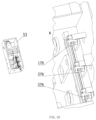
- FIG. 18 is a group of partial enlarged cross-sectional views of driving member A, driving member B and driving member C.
- the three groups of views from left to right respectively represent partial enlarged cross-sections of driving member A, driving member B and driving member C.
- Figures, the upper images of each group of images are partial enlarged images of the lower images.
- FIG. 19 is a schematic structural diagram of transmission tooth A, transmission tooth B and transmission tooth C. From left to right are the structural schematic diagrams of transmission tooth A, transmission tooth B and transmission tooth C respectively.
- FIG. 20 is a schematic structural diagram of FIG. 8 with the box and other parts removed.
- FIG. 21 is a schematic structural diagram of gear D and the external ring gear.
- FIG. 22 is a schematic structural diagram of FIG. 21 with bracket J and other parts removed.
- FIG. 23 is a partial structural view and an enlarged view of FIG. 21 after removing the motor, bracket I, bracket J and other parts.
- the left image is a partial structural view
- the right image is a partial enlarged view of E in the left image.
- FIG. 24 is a structural diagram and a partial enlarged view of the stent I.
- the left picture is a structural diagram
- the right picture is a partial enlarged view of J in the left picture.
- FIG. 25 is a structural diagram and a partial enlarged view of the bracket J.
- the left picture is a structural diagram
- the right picture is a partial enlarged view of F in the left picture.
- the power switch ( 58 ) on the enclosure ( 53 ) is set to the OFF position ( 581 ).
- the solar panel ( 4 ) is fixed on three solar panel mounting plates ( 41 ).
- Photosensitive components A ( 1 ), B ( 2 ), and C ( 3 ) are each fixedly connected to the D-shaped shafts on the solar panel mounting plates ( 41 ) and are distributed at 120 intervals.
- Rockers A ( 11 ), B ( 21 ), and C ( 31 ) are hinged to the D-shaped shafts on the solar panel mounting plates ( 41 ) and correspond to photosensitive components A ( 1 ), B ( 2 ), and C ( 3 ) respectively (to detect the light intensity in real-time for the solar rays to be approximately perpendicular to the solar panel ( 4 )).
- Rotating arms A ( 12 ), B ( 22 ), and C ( 32 ) are each hinged to rockers A ( 11 ), B ( 21 ), and C ( 31 ) respectively, to enable the solar panel ( 4 ) to rotate in both azimuth and elevation directions.
- Micro switches A ( 111 ), B ( 211 ), and C ( 311 ) are fixed on rotating arms A ( 12 ), B ( 22 ), and C ( 32 ) respectively.
- Axis A ( 131 ) is connected to bracket D ( 531 ) through bearing A ( 132 ) and is also fitted with axis B ( 231 ), within which axis C ( 331 ) is nested.
- One end of rotating arms A ( 12 ), B ( 22 ), and C ( 32 ) is fixedly connected to axis A ( 131 ), B ( 231 ), and C ( 331 ) respectively.
- Bevel gears A ( 13 ), B ( 23 ), and C ( 33 ) are each fixedly connected to axis A ( 131 ), B ( 231 ), and C ( 331 ) respectively (achieving continuous adjustment of the solar panel angle through worm gear, gear transmission, rocker, and rotating arm transmission).
- Axis G ( 151 ) is connected to the enclosure ( 53 ) through bearings and elastic stop ring D ( 152 ), and is also fitted with axis H ( 251 ), within which axis I ( 351 ) is nested.
- Bevel gears G ( 15 ), H ( 25 ), and I ( 35 ) are each fixedly connected to axis G ( 151 ), H ( 251 ), and I ( 351 ) respectively, and are engaged with bevel gears A ( 13 ), B ( 23 ), and C ( 33 ) respectively.
- Axis D ( 141 ) is connected to the enclosure ( 53 ) through bearing D ( 142 ) and bracket A ( 145 ).
- Axis D ( 141 ) is also fitted with axis E ( 241 ) within it.
- Axis E ( 241 ) is connected to bracket B ( 245 ) through bearing E ( 242 ).
- Axis E ( 241 ) is nested with axis F ( 341 ) inside, and axis F ( 341 ) is connected to bracket C ( 345 ) and the enclosure ( 53 ) through bearing F ( 342 ).
- Bevel gears D ( 14 ), E ( 24 ), and F ( 34 ) are each fixedly connected to axis D ( 141 ), E ( 241 ), and F ( 341 ) respectively, and are engaged with bevel gears A ( 13 ), B ( 23 ), and C ( 33 ) respectively.
- Worm gear A ( 143 ) is fixedly connected to axis D ( 141 ), worm gear B ( 243 ) is fixedly connected to axis E ( 241 ), and worm gear C ( 343 ) is fixedly connected to axis F ( 341 ).
- worm gear A ( 146 ) On worm gear A ( 146 ), axis M ( 1461 ) is connected to bracket F ( 562 ), bracket G ( 563 ), and the enclosure ( 53 ) through bearing G ( 172 ), and worm gear A ( 146 ) meshes with worm gear A ( 143 ); on worm gear B ( 246 ), axis N ( 2461 ) is connected to bracket F ( 562 ), bracket G ( 563 ), and the enclosure ( 53 ) through bearing H ( 272 ), and worm gear B ( 246 ) meshes with worm gear B ( 243 ); on worm gear C ( 346 ), axis O ( 3461 ) is connected to bracket E ( 561 ), bracket F ( 562 ), bracket G ( 563 ), and the enclosure ( 53 ) through bearing I ( 372 ), and worm gear C ( 346 ) meshes with worm gear C ( 343 ) (worm gear and worm structure with self-locking function).
- Gears A ( 147 ), B ( 247 ), and C ( 347 ) are each connected to worm gear A ( 146 ), worm gear B ( 246 ), and worm gear C ( 346 ) respectively through bearings.
- Drive component A ( 148 ) is fixedly connected to axis M ( 1461 )
- drive component B ( 248 ) is fixedly connected to axis N ( 2461 )
- drive component C ( 348 ) is fixedly connected to axis O ( 3461 ).
- Slider A ( 1484 ) is fixedly connected to inclined plane slider A ( 1481 ) through double-ended threaded rod A ( 1482 ), and double-ended threaded rod A ( 1482 ) is fitted with reset spring D ( 1483 ).
- Transmission gear A ( 1485 ) is hinged to slider A ( 1484 ) (rotatable left and right by 5° to ensure meshing of gears).
- Slider B ( 2484 ) is fixedly connected to inclined plane slider B ( 2481 ) through double-ended threaded rod B ( 2482 ), and double-ended threaded rod B ( 2482 ) is fitted with reset spring E ( 2483 ).
- Transmission gear B ( 2485 ) is hinged to slider B ( 2484 ) (rotatable left and right by 5° to ensure meshing of gears).
- Slider C ( 3484 ) is fixedly connected to inclined plane slider C ( 3481 ) through double-ended threaded rod C ( 3482 ), and double-ended threaded rod C ( 3482 ) is fitted with reset spring F ( 3483 ).
- Transmission gear C ( 3485 ) is hinged to slider C ( 3484 ) (rotatable left and right by 5° to ensure meshing of gears).
- Slider A ( 1484 ) is located on the outer side of baffle E ( 1487 ), inclined plane slider A ( 1481 ) is located on the inner side of baffle E ( 1487 ), and one end of reset spring D ( 1483 ) contacts inclined plane slider A ( 1481 ), while the other end contacts the inner wall of baffle E ( 1487 ).
- Slider B ( 2484 ) is located on the outer side of baffle F ( 2487 ), inclined plane slider B ( 2481 ) is located on the inner side of baffle F ( 2487 ), and one end of reset spring E ( 2483 ) contacts inclined plane slider B ( 2481 ), while the other end contacts the inner wall of baffle F ( 2487 ).
- Slider C ( 3484 ) is located on the outer side of baffle G ( 3487 ), inclined plane slider C ( 3481 ) is located on the inner side of baffle G ( 3487 ), and one end of reset spring F ( 3483 ) contacts inclined plane slider C ( 3481 ), while the other end contacts the inner wall of baffle G ( 3487 ).
- Transmission gear A ( 1485 ), transmission gear B ( 2485 ), and transmission gear C ( 3485 ) are in a disengaged state from internal gear A ( 1471 ), internal gear B ( 2471 ), and internal gear C ( 3471 ) respectively.
- Mobile sleeve A ( 17 ), mobile sleeve B ( 27 ), and mobile sleeve C ( 37 ) are each slidably connected to sleeve A ( 176 ), sleeve B ( 276 ), and sleeve C ( 376 ) respectively through D-shaped holes, and are fixedly connected to bracket G ( 563 ).
- reset spring N ( 162 ), reset spring O ( 262 ), and reset spring P ( 362 ) is fixedly connected to sleeve A ( 176 ), sleeve B ( 276 ), and sleeve C ( 376 ) respectively, while the other end is fixedly connected to mobile sleeve A ( 17 ), mobile sleeve B ( 27 ), and mobile sleeve C ( 37 ) respectively.
- Mobile sleeve A ( 17 ), mobile sleeve B ( 27 ), and mobile sleeve C ( 37 ) each make contact with micro switch D ( 171 ), micro switch E ( 271 ), and micro switch F ( 371 ) respectively.
- Lever A ( 16 ), lever B ( 26 ), and lever C ( 36 ) are each slidably connected to shaft J ( 564 ), shaft K ( 565 ), and shaft L ( 566 ) respectively through D-shaped holes, and each of shaft J ( 564 ), shaft K ( 565 ), and shaft L ( 566 ) is fitted with reset spring A ( 161 ), reset spring B ( 261 ), and reset spring C ( 361 ) respectively.
- the hooks at the lower end of lever A ( 16 ), lever B ( 26 ), and lever C ( 36 ) are respectively connected to annular grooves A ( 173 ) on mobile sleeve A ( 17 ), annular grooves B ( 273 ) on mobile sleeve B ( 27 ), and annular grooves C ( 373 ) on mobile sleeve C ( 37 ).
- the pushrods of electromagnets A ( 163 ), B ( 263 ), and C ( 363 ) each make contact with one side of lever A ( 16 ), lever B ( 26 ), and lever C ( 36 ) respectively.
- the slide rail E ( 576 ) on the slider ( 57 ) is connected to the internal mobile groove of the enclosure ( 53 ), and one end of the slider ( 57 ) is equipped with reset spring G ( 575 ), the pushrod of electromagnet D ( 574 ) makes contact with one end of the slider ( 57 ).
- the triangular components D ( 577 ), E ( 578 ), and F ( 579 ) on the slider ( 57 ) each make sliding contact with triangular components A ( 174 ) on mobile sleeve A ( 17 ), triangular components B ( 274 ) on mobile sleeve B ( 27 ), and triangular components C ( 374 ) on mobile sleeve C ( 37 ).
- Gear A ( 147 ) meshes with gear B ( 247 ), gear B ( 247 ) meshes with gear C ( 347 ), and gear D ( 63 ) meshes with gear B ( 247 ).
- the rotor shaft of the motor ( 6 ) is fixedly connected to the sun gear ( 65 ), the planetary gear ( 651 ) meshes with the sun gear ( 65 ), and the planetary gear ( 651 ) is fitted with a planetary carrier ( 652 ), and the shaft M ( 6521 ) on the planetary carrier ( 652 ) is fixedly connected to gear D ( 63 ).
- the planetary gear ( 651 ) meshes with the external gear ( 64 ), forming a planetary gear system through the sun gear ( 65 ), planetary gear ( 651 ), external gear ( 64 ), and planetary carrier ( 652 ).
- the external gear ( 64 ) is equipped with ratchet A ( 641 ), ratchet B ( 642 ), and circular convex platform ( 643 ).
- Micro switch G ( 644 ) and micro switch H ( 645 ) are located on both sides of the circular convex platform ( 643 ) with an angle of 5°.
- the external gear ( 64 ) is locked by the ratchet pawl.
- the locking structure of the external gear ( 64 ) will be quickly released.
- the planetary gear carrier does not rotate due to the self-locking of the worm gear.
- the motor's drive causes the external gear ( 64 ) to rotate.
- inclined slider D ( 613 ) contacts the other side of pawl A ( 611 ), and the slide rail A ( 6132 ) on inclined slider D ( 613 ) is connected to the slide groove B ( 661 ) on bracket I ( 61 ).
- One side of reset spring I ( 6131 ) contacts the bottom end of inclined slider D ( 613 ), and the other side contacts bracket I ( 61 ).
- the inclined surface of inclined slider D ( 613 ) contacts the inclined surface of inclined slide board A ( 614 ), and the slide rail B ( 6141 ) on inclined slide board A ( 614 ) is connected to the slide groove A ( 66 ) on bracket I ( 61 ).
- reset spring J ( 6142 ) is fixedly connected to one end of inclined slide board A ( 614 ), and the other side is fixedly connected to bracket I ( 61 ).
- the pushrod of electromagnet F ( 6143 ) contacts one end of the groove inside inclined slide board A ( 614 ), and the pushrod of electromagnet E ( 612 ) contacts the upper end of inclined slider D ( 613 ).
- Pawl B ( 621 ) meshes with ratchet B ( 642 ) and is sleeved on shaft O ( 674 ) of bracket J ( 62 ).
- One end of reset spring K ( 6211 ) is fixedly connected to pawl B ( 621 ), and the other end is fixedly connected to stopper plate D ( 673 ).
- inclined slider E ( 623 ) contacts the other end of pawl B ( 621 ), and the slide rail D ( 6232 ) on inclined slider E ( 623 ) is connected to the slide groove D ( 671 ) on bracket J ( 62 ).
- One side of reset spring L ( 6231 ) contacts the bottom end of inclined slider E ( 623 ), and the other side contacts bracket J ( 62 ).
- the inclined surface of inclined slider E ( 623 ) contacts the inclined surface of inclined slide board B ( 624 ), and the slide rail C ( 6241 ) on inclined slide board B ( 624 ) is connected to the slide groove C ( 67 ) on bracket J ( 62 ).
- One side of reset spring M ( 6242 ) is fixedly connected to one end of inclined slide board B ( 624 ), and the other end is fixedly connected to bracket J ( 62 ).
- Electromagnet H ( 6243 )'s push rod contacts one end of the recess on Inclined Slider B ( 624 ), and Electromagnet G ( 622 )'s push rod contacts the upper end of Inclined Slider E ( 623 ).
- Bracket I ( 61 ), Bracket J ( 62 ), and the chassis ( 53 ) are fixedly connected.
- Electromagnet A ( 163 ) is powered, driving Lever A ( 16 ) to move along the axis of Shaft J ( 564 ), driving the moving sleeve A ( 17 ) to move along the axis of Sleeve A ( 176 ), the moving sleeve A ( 17 ) pushes the Inclined Slider A ( 1481 ) along the radial extrusion of the driving member A ( 148 ), causing the Drive Tooth A ( 1485 ) to mesh with the Internal Gear A ( 1471 ); the triangular component A ( 174 ) on the moving sleeve A ( 17 ) squeezes the triangular component D ( 577 ) on the slide plate ( 57 ) to the left.
- Gear D ( 63 ) rotates forward, driving Gear B ( 247 ) to rotate in reverse, which drives Gear A ( 147 ) to rotate forward.
- Gear A ( 147 ) drives Drive Tooth A ( 1485 ) to rotate forward, which in turn drives Drive Component A ( 148 ) to rotate forward.
- Drive Component A ( 148 ) drives Worm A ( 146 ) to rotate forward, which drives Worm Gear A ( 143 ) to rotate forward.
- Worm Gear A ( 143 ) drives Bevel Gear D ( 14 ) to rotate forward, which drives Bevel Gear A ( 13 ) to rotate in reverse.
- Bevel Gear A ( 13 ) drives Arm A ( 12 ) to rotate in reverse, causing Lever A ( 11 ) to descend, adjusting the angle between the solar panel mount ( 41 ) and the ground.
- Lever A ( 11 ) touches Microswitch A ( 111 )
- Lever B ( 21 ) touches Microswitch K ( 213 )
- Lever C ( 31 ) touches Microswitch L ( 313 )
- the control module ( 54 ) receives the signal, and the motor ( 6 ) stops (on one hand, it drives the solar panel to move to the predetermined position, on the other hand, it checks if there is any malfunction in the device);
- Electromagnet D ( 574 ) is powered, pushing the slide plate ( 57 ) to the left.
- the control module continuously monitors the voltage values of Photosensitive Element A ( 1 ), Photosensitive Element B ( 2 ), and Photosensitive Element C ( 3 ).
- the voltage values of Photosensitive Element A ( 1 ), Photosensitive Element B ( 2 ), and Photosensitive Element C ( 3 ) differ due to variations in light intensity.
- the control module ( 54 ) sends a signal.
- the lever corresponding to the maximum voltage difference will change first, i.e., the corresponding electromagnet is powered, causing the corresponding drive tooth to engage with the internal gear (transferring the power of the motor to the worm).
- the corresponding lever is then raised or lowered through the transmission of gears, worm gears, and bevel gears to reduce the voltage difference.
- the adjustment ends.
- the control module then rechecks the voltage differences between Photosensitive Element A ( 1 ), Photosensitive Element B ( 2 ), and Photosensitive Element C ( 3 ). If any voltage difference exceeds the predefined threshold value, the one with the highest voltage difference is selected again, and the device adjusts its orientation accordingly.
- This process repeats until all voltage differences between any two elements are less than the predefined threshold value. When all voltage differences between any two elements are less than the predefined threshold value, it is considered that the device has adjusted to the required position. At this point, the solar panel is approximately perpendicular to the sunlight, and the solar panel receives the maximum approximate flux of sunlight.
- Electromagnet A ( 163 ) is powered, causing Lever A ( 16 ) to move along with the Mobile Sleeve A ( 17 ), engaging the Drive Tooth A ( 1485 ) with the Internal Gear A ( 1471 ) (transferring the motor's power to Worm A ( 146 )).
- the motor is powered, driving Lever A ( 11 ) to rise or fall through the transmission of gears, worm gears, and bevel gears.
- Lever A ( 11 ) touches Microswitch A ( 111 ) the motor stops.
- Lever B ( 21 ) and Lever C ( 31 ) are similar to that of Lever A ( 11 ), with Lever B ( 21 ) and Lever C ( 31 ) contacting Microswitch K ( 213 ) and Microswitch L ( 313 ), respectively.
- the solar panel fixture ( 41 ) returns to its initial position, preparing for the next day's operation.
- the device utilizes a mechanism with a self-locking function using a worm gear system to achieve self-locking (to prevent wind loads from affecting the orientation of the solar panel).
- a malfunction such as the worm gear system or lever getting damaged or stuck, causing gears A ( 147 ), B ( 247 ), C ( 347 ), D ( 63 ), and the planetary frame ( 652 ) to fail to operate
- the control module will send a signal.
- This signal causes Pawl A ( 641 ), Pawl A ( 611 ), Pawl B ( 642 ), and Pawl B ( 621 ) to disengage simultaneously (Electromagnet E ( 612 ) is powered, pushing down the Inclined Slider D ( 613 ), which moves the Inclined Slider A ( 614 ) radially.
- Inclined Slider D ( 613 ) separates from the inclined surface of Inclined Slider A ( 614 )
- Inclined Slider A ( 614 ) returns to its original position under the action of Reset Spring J ( 6142 ), and Electromagnet E ( 612 ) loses power, causing Pawl A ( 641 ) and Pawl A ( 611 ) to disengage.
- Electromagnet G ( 622 ) is powered, pushing down Inclined Slider E ( 623 ), which moves Inclined Slider B ( 624 ) radially.
- Inclined Slider B ( 624 ) returns to its original position under the action of Reset Spring M ( 6242 ), and Electromagnet G ( 622 ) loses power, causing Pawl B ( 642 ) and Pawl B ( 621 ) to disengage).
- the locking of the external gear ( 64 ) is released. Under the drive of the motor ( 6 ) rotor shaft through the planetary gear system, the external gear ( 64 ) rotates.
Landscapes
- Engineering & Computer Science (AREA)
- General Engineering & Computer Science (AREA)
- Life Sciences & Earth Sciences (AREA)
- Sustainable Development (AREA)
- Mechanical Engineering (AREA)
- Power Engineering (AREA)
- Physics & Mathematics (AREA)
- Sustainable Energy (AREA)
- Thermal Sciences (AREA)
- Chemical & Material Sciences (AREA)
- Combustion & Propulsion (AREA)
- Transmission Devices (AREA)
- Photovoltaic Devices (AREA)
Abstract
Description
Claims (9)
Applications Claiming Priority (3)
| Application Number | Priority Date | Filing Date | Title |
|---|---|---|---|
| CN2023102113588 | 2023-03-07 | ||
| CN202310211358.8A CN116667759B (en) | 2023-03-07 | 2023-03-07 | Photovoltaic power generation device capable of automatically tracking sun |
| CN202310211358.8 | 2023-03-07 |
Publications (2)
| Publication Number | Publication Date |
|---|---|
| US20240305240A1 US20240305240A1 (en) | 2024-09-12 |
| US12191800B2 true US12191800B2 (en) | 2025-01-07 |
Family
ID=87716009
Family Applications (1)
| Application Number | Title | Priority Date | Filing Date |
|---|---|---|---|
| US18/597,962 Active US12191800B2 (en) | 2023-03-07 | 2024-03-07 | Automatic solar tracking photovoltaic power generation device |
Country Status (2)
| Country | Link |
|---|---|
| US (1) | US12191800B2 (en) |
| CN (1) | CN116667759B (en) |
Families Citing this family (8)
| Publication number | Priority date | Publication date | Assignee | Title |
|---|---|---|---|---|
| CN118824818B (en) * | 2024-09-18 | 2024-11-29 | 奥伟纳(常州)光电科技有限公司 | High vacuum exhaust equipment of ultraviolet fluorescent tube |
| CN119362657B (en) * | 2024-12-20 | 2025-07-08 | 深圳市龙星辰电源有限公司 | An open-frame medical power supply box |
| CN119787947B (en) * | 2024-12-31 | 2025-11-11 | 广东新佳盟电子科技有限公司 | Outdoor intelligent environment-adaptive portable energy storage power supply |
| CN121791797A (en) * | 2025-01-21 | 2026-04-03 | 南京逸顺建筑装饰工程有限公司 | High-low architecture type photovoltaic panel support |
| CN120176604B (en) * | 2025-02-17 | 2026-01-30 | 中交路桥建设有限公司 | Intelligent monitoring device suitable for foundation pit deformation under high-voltage line |
| CN120300639B (en) * | 2025-06-12 | 2025-09-12 | 陕西长鑫精密装备有限公司 | A field emergency starting power supply |
| CN120342301A (en) * | 2025-06-16 | 2025-07-18 | 福建金固美能源科技有限公司 | A solar photovoltaic support and control method |
| CN120900974B (en) * | 2025-10-09 | 2025-12-26 | 江苏牧心胜科技有限公司 | Solar cell sorting assembly, device and sorting method |
Citations (6)
| Publication number | Priority date | Publication date | Assignee | Title |
|---|---|---|---|---|
| US20100147286A1 (en) * | 2008-12-04 | 2010-06-17 | Xiao Dong Xiang | Systems and methods including features of synchronized movement across and array of solar collectors |
| US20180239059A1 (en) * | 2016-07-18 | 2018-08-23 | Omni Lps. Co., Ltd. | Lightning strike alarm system using bipolar conventional air terminal |
| US20190356266A1 (en) * | 2018-05-15 | 2019-11-21 | Miasole Photovoltaic Technology Co., Ltd. | Solar power supply device, power emergency draw-bar box and power supply system |
| US20220299220A1 (en) * | 2021-03-16 | 2022-09-22 | Samsung Electronics Co., Ltd. | Air purifier and controlling method thereof |
| CN218549837U (en) | 2022-08-25 | 2023-02-28 | 赵章凯 | Power generation self-tracking solar power generation panel |
| US20230146184A1 (en) * | 2021-11-09 | 2023-05-11 | Johnathan McCutcheon | Low energy motorized platform comprising solar panels |
Family Cites Families (7)
| Publication number | Priority date | Publication date | Assignee | Title |
|---|---|---|---|---|
| CN102638194A (en) * | 2012-03-21 | 2012-08-15 | 杭州帷盛太阳能科技有限公司 | Three-shaft parallel solar tracker |
| CN108988765A (en) * | 2018-08-10 | 2018-12-11 | 常州大学 | Solar panel electrically powered steering apparatus using same |
| CN110112817A (en) * | 2019-04-29 | 2019-08-09 | 深圳市网源电气有限公司 | Energy-saving AC/DC integrated charging pile |
| CN111781957A (en) * | 2020-07-02 | 2020-10-16 | 嘉兴学院 | A sun automatic tracking device and control method |
| CN111835274A (en) * | 2020-08-24 | 2020-10-27 | 嘉兴奥锶特光电科技有限公司 | Solar cell panel capable of automatically adjusting angle along with sun |
| CN114142796A (en) * | 2021-10-27 | 2022-03-04 | 国家电投集团曲阳新能源发电有限公司 | Solar photovoltaic support capable of automatically tracking illumination angle |
| CN114744959A (en) * | 2022-05-12 | 2022-07-12 | 天津中物绿色新能源科技有限公司 | A multi-angle steering photovoltaic tracking bracket |
-
2023
- 2023-03-07 CN CN202310211358.8A patent/CN116667759B/en active Active
-
2024
- 2024-03-07 US US18/597,962 patent/US12191800B2/en active Active
Patent Citations (6)
| Publication number | Priority date | Publication date | Assignee | Title |
|---|---|---|---|---|
| US20100147286A1 (en) * | 2008-12-04 | 2010-06-17 | Xiao Dong Xiang | Systems and methods including features of synchronized movement across and array of solar collectors |
| US20180239059A1 (en) * | 2016-07-18 | 2018-08-23 | Omni Lps. Co., Ltd. | Lightning strike alarm system using bipolar conventional air terminal |
| US20190356266A1 (en) * | 2018-05-15 | 2019-11-21 | Miasole Photovoltaic Technology Co., Ltd. | Solar power supply device, power emergency draw-bar box and power supply system |
| US20220299220A1 (en) * | 2021-03-16 | 2022-09-22 | Samsung Electronics Co., Ltd. | Air purifier and controlling method thereof |
| US20230146184A1 (en) * | 2021-11-09 | 2023-05-11 | Johnathan McCutcheon | Low energy motorized platform comprising solar panels |
| CN218549837U (en) | 2022-08-25 | 2023-02-28 | 赵章凯 | Power generation self-tracking solar power generation panel |
Also Published As
| Publication number | Publication date |
|---|---|
| CN116667759A (en) | 2023-08-29 |
| CN116667759B (en) | 2023-11-10 |
| US20240305240A1 (en) | 2024-09-12 |
Similar Documents
| Publication | Publication Date | Title |
|---|---|---|
| US12191800B2 (en) | Automatic solar tracking photovoltaic power generation device | |
| CN102195527B (en) | Electric push rod-controlled photovoltaic generating set for automatically tracking sun with double shafts | |
| CN103475269B (en) | Small-size Fresnel concentrated solar power generation system | |
| KR101269635B1 (en) | The solar tracking apparatus for a sunlight power generator | |
| CN211123774U (en) | Double-shaft tracking controller of photovoltaic power generation system | |
| KR101398292B1 (en) | Tracking Type floating Photovoltaic system | |
| CN110762465A (en) | Intelligent solar street lamp | |
| KR20150018658A (en) | Hybrid Generation Systems using Solar and Wind Energy | |
| CN110700998B (en) | Sun tracking type wind-solar complementary building power supply device | |
| CN101499743A (en) | Turbine arch shaped rolling rack transmitting two-dimensional sunlight automatically tracing apparatus | |
| CN112947141A (en) | Security protection supervisory equipment of wisdom building site management and control platform | |
| CN101599723B (en) | Toothed belt turbine transmission three-dimensional automatic solar tracking device | |
| CN101567399B (en) | General three-dimensional automatic tracking device of photovoltaic battery panel | |
| CN213872523U (en) | Wisdom street lamp with vehicle monitoring function | |
| CN201652103U (en) | Vertical drive shaft variable angle linear drive three-dimensional automatic tracking daylighting solar street light | |
| CN112013336B (en) | Device for changing angle of street lamp solar cell panel along with rotation of sun | |
| CN109302128B (en) | Solar panel for automatic marine meteorological observation instrument | |
| CN220682517U (en) | Solar trolley | |
| CN111021286A (en) | Lighting method of intelligent road lighting isolation belt | |
| CN218237288U (en) | Self-resetting sun-chasing type integrated solar street lamp | |
| CN110825125B (en) | Photovoltaic support is tracked to integrative biax of every single move of curved surface formula gyration | |
| CN213810378U (en) | A solar street light photovoltaic panel that can track changes in the angle of sunlight | |
| CN116191999A (en) | A photovoltaic energy storage device and system with a remote safety monitoring mechanism | |
| CN212063901U (en) | Intelligent monitoring device for photovoltaic panel | |
| CN210609031U (en) | Automatic deviation adjusting device for photovoltaic equipment |
Legal Events
| Date | Code | Title | Description |
|---|---|---|---|
| AS | Assignment |
Owner name: SUZHOU VACATIONAL UNIVERSITY, CHINA Free format text: ASSIGNMENT OF ASSIGNORS INTEREST;ASSIGNORS:BAO, SIYUAN;ZHANG, YONGKANG;ZHONG, YUN;REEL/FRAME:066675/0383 Effective date: 20240306 Owner name: SUZHOU UNIVERSITY OF SCIENCE AND TECHNOLOGY, CHINA Free format text: ASSIGNMENT OF ASSIGNORS INTEREST;ASSIGNORS:BAO, SIYUAN;ZHANG, YONGKANG;ZHONG, YUN;REEL/FRAME:066675/0383 Effective date: 20240306 |
|
| FEPP | Fee payment procedure |
Free format text: ENTITY STATUS SET TO UNDISCOUNTED (ORIGINAL EVENT CODE: BIG.); ENTITY STATUS OF PATENT OWNER: SMALL ENTITY |
|
| FEPP | Fee payment procedure |
Free format text: ENTITY STATUS SET TO SMALL (ORIGINAL EVENT CODE: SMAL); ENTITY STATUS OF PATENT OWNER: SMALL ENTITY |
|
| STPP | Information on status: patent application and granting procedure in general |
Free format text: NOTICE OF ALLOWANCE MAILED -- APPLICATION RECEIVED IN OFFICE OF PUBLICATIONS |
|
| STPP | Information on status: patent application and granting procedure in general |
Free format text: PUBLICATIONS -- ISSUE FEE PAYMENT RECEIVED |
|
| STPP | Information on status: patent application and granting procedure in general |
Free format text: PUBLICATIONS -- ISSUE FEE PAYMENT VERIFIED |
|
| STCF | Information on status: patent grant |
Free format text: PATENTED CASE |