US12095129B2 - Reforming catalyst pattern for fuel cell operated with enhanced CO2 utilization - Google Patents
Reforming catalyst pattern for fuel cell operated with enhanced CO2 utilization Download PDFInfo
- Publication number
- US12095129B2 US12095129B2 US18/110,097 US202318110097A US12095129B2 US 12095129 B2 US12095129 B2 US 12095129B2 US 202318110097 A US202318110097 A US 202318110097A US 12095129 B2 US12095129 B2 US 12095129B2
- Authority
- US
- United States
- Prior art keywords
- fuel cell
- anode
- cathode
- reforming
- catalyst
- Prior art date
- Legal status (The legal status is an assumption and is not a legal conclusion. Google has not performed a legal analysis and makes no representation as to the accuracy of the status listed.)
- Active
Links
Images


Classifications
-
- H—ELECTRICITY
- H01—ELECTRIC ELEMENTS
- H01M—PROCESSES OR MEANS, e.g. BATTERIES, FOR THE DIRECT CONVERSION OF CHEMICAL ENERGY INTO ELECTRICAL ENERGY
- H01M8/00—Fuel cells; Manufacture thereof
- H01M8/06—Combination of fuel cells with means for production of reactants or for treatment of residues
- H01M8/0606—Combination of fuel cells with means for production of reactants or for treatment of residues with means for production of gaseous reactants
- H01M8/0612—Combination of fuel cells with means for production of reactants or for treatment of residues with means for production of gaseous reactants from carbon-containing material
- H01M8/0618—Reforming processes, e.g. autothermal, partial oxidation or steam reforming
-
- H—ELECTRICITY
- H01—ELECTRIC ELEMENTS
- H01M—PROCESSES OR MEANS, e.g. BATTERIES, FOR THE DIRECT CONVERSION OF CHEMICAL ENERGY INTO ELECTRICAL ENERGY
- H01M8/00—Fuel cells; Manufacture thereof
- H01M8/14—Fuel cells with fused electrolytes
- H01M8/144—Fuel cells with fused electrolytes characterised by the electrolyte material
- H01M8/145—Fuel cells with fused electrolytes characterised by the electrolyte material comprising carbonates
-
- H—ELECTRICITY
- H01—ELECTRIC ELEMENTS
- H01M—PROCESSES OR MEANS, e.g. BATTERIES, FOR THE DIRECT CONVERSION OF CHEMICAL ENERGY INTO ELECTRICAL ENERGY
- H01M8/00—Fuel cells; Manufacture thereof
- H01M8/14—Fuel cells with fused electrolytes
- H01M2008/147—Fuel cells with molten carbonates
-
- H—ELECTRICITY
- H01—ELECTRIC ELEMENTS
- H01M—PROCESSES OR MEANS, e.g. BATTERIES, FOR THE DIRECT CONVERSION OF CHEMICAL ENERGY INTO ELECTRICAL ENERGY
- H01M2300/00—Electrolytes
- H01M2300/0017—Non-aqueous electrolytes
- H01M2300/0048—Molten electrolytes used at high temperature
- H01M2300/0051—Carbonates
-
- H—ELECTRICITY
- H01—ELECTRIC ELEMENTS
- H01M—PROCESSES OR MEANS, e.g. BATTERIES, FOR THE DIRECT CONVERSION OF CHEMICAL ENERGY INTO ELECTRICAL ENERGY
- H01M4/00—Electrodes
- H01M4/86—Inert electrodes with catalytic activity, e.g. for fuel cells
- H01M4/8605—Porous electrodes
- H01M4/861—Porous electrodes with a gradient in the porosity
-
- H—ELECTRICITY
- H01—ELECTRIC ELEMENTS
- H01M—PROCESSES OR MEANS, e.g. BATTERIES, FOR THE DIRECT CONVERSION OF CHEMICAL ENERGY INTO ELECTRICAL ENERGY
- H01M4/00—Electrodes
- H01M4/86—Inert electrodes with catalytic activity, e.g. for fuel cells
- H01M4/8636—Inert electrodes with catalytic activity, e.g. for fuel cells with a gradient in another property than porosity
-
- H—ELECTRICITY
- H01—ELECTRIC ELEMENTS
- H01M—PROCESSES OR MEANS, e.g. BATTERIES, FOR THE DIRECT CONVERSION OF CHEMICAL ENERGY INTO ELECTRICAL ENERGY
- H01M8/00—Fuel cells; Manufacture thereof
- H01M8/04—Auxiliary arrangements, e.g. for control of pressure or for circulation of fluids
- H01M8/04082—Arrangements for control of reactant parameters, e.g. pressure or concentration
- H01M8/04089—Arrangements for control of reactant parameters, e.g. pressure or concentration of gaseous reactants
- H01M8/04119—Arrangements for control of reactant parameters, e.g. pressure or concentration of gaseous reactants with simultaneous supply or evacuation of electrolyte; Humidifying or dehumidifying
- H01M8/04156—Arrangements for control of reactant parameters, e.g. pressure or concentration of gaseous reactants with simultaneous supply or evacuation of electrolyte; Humidifying or dehumidifying with product water removal
- H01M8/04179—Arrangements for control of reactant parameters, e.g. pressure or concentration of gaseous reactants with simultaneous supply or evacuation of electrolyte; Humidifying or dehumidifying with product water removal by purging or increasing flow or pressure of reactants
-
- H—ELECTRICITY
- H01—ELECTRIC ELEMENTS
- H01M—PROCESSES OR MEANS, e.g. BATTERIES, FOR THE DIRECT CONVERSION OF CHEMICAL ENERGY INTO ELECTRICAL ENERGY
- H01M8/00—Fuel cells; Manufacture thereof
- H01M8/04—Auxiliary arrangements, e.g. for control of pressure or for circulation of fluids
- H01M8/04298—Processes for controlling fuel cells or fuel cell systems
- H01M8/04313—Processes for controlling fuel cells or fuel cell systems characterised by the detection or assessment of variables; characterised by the detection or assessment of failure or abnormal function
- H01M8/0438—Pressure; Ambient pressure; Flow
- H01M8/04388—Pressure; Ambient pressure; Flow of anode reactants at the inlet or inside the fuel cell
-
- H—ELECTRICITY
- H01—ELECTRIC ELEMENTS
- H01M—PROCESSES OR MEANS, e.g. BATTERIES, FOR THE DIRECT CONVERSION OF CHEMICAL ENERGY INTO ELECTRICAL ENERGY
- H01M8/00—Fuel cells; Manufacture thereof
- H01M8/04—Auxiliary arrangements, e.g. for control of pressure or for circulation of fluids
- H01M8/04298—Processes for controlling fuel cells or fuel cell systems
- H01M8/04313—Processes for controlling fuel cells or fuel cell systems characterised by the detection or assessment of variables; characterised by the detection or assessment of failure or abnormal function
- H01M8/0438—Pressure; Ambient pressure; Flow
- H01M8/04395—Pressure; Ambient pressure; Flow of cathode reactants at the inlet or inside the fuel cell
-
- H—ELECTRICITY
- H01—ELECTRIC ELEMENTS
- H01M—PROCESSES OR MEANS, e.g. BATTERIES, FOR THE DIRECT CONVERSION OF CHEMICAL ENERGY INTO ELECTRICAL ENERGY
- H01M8/00—Fuel cells; Manufacture thereof
- H01M8/04—Auxiliary arrangements, e.g. for control of pressure or for circulation of fluids
- H01M8/04298—Processes for controlling fuel cells or fuel cell systems
- H01M8/04313—Processes for controlling fuel cells or fuel cell systems characterised by the detection or assessment of variables; characterised by the detection or assessment of failure or abnormal function
- H01M8/0438—Pressure; Ambient pressure; Flow
- H01M8/04402—Pressure; Ambient pressure; Flow of anode exhausts
-
- H—ELECTRICITY
- H01—ELECTRIC ELEMENTS
- H01M—PROCESSES OR MEANS, e.g. BATTERIES, FOR THE DIRECT CONVERSION OF CHEMICAL ENERGY INTO ELECTRICAL ENERGY
- H01M8/00—Fuel cells; Manufacture thereof
- H01M8/04—Auxiliary arrangements, e.g. for control of pressure or for circulation of fluids
- H01M8/04298—Processes for controlling fuel cells or fuel cell systems
- H01M8/04313—Processes for controlling fuel cells or fuel cell systems characterised by the detection or assessment of variables; characterised by the detection or assessment of failure or abnormal function
- H01M8/0438—Pressure; Ambient pressure; Flow
- H01M8/0441—Pressure; Ambient pressure; Flow of cathode exhausts
-
- H—ELECTRICITY
- H01—ELECTRIC ELEMENTS
- H01M—PROCESSES OR MEANS, e.g. BATTERIES, FOR THE DIRECT CONVERSION OF CHEMICAL ENERGY INTO ELECTRICAL ENERGY
- H01M8/00—Fuel cells; Manufacture thereof
- H01M8/04—Auxiliary arrangements, e.g. for control of pressure or for circulation of fluids
- H01M8/04298—Processes for controlling fuel cells or fuel cell systems
- H01M8/04313—Processes for controlling fuel cells or fuel cell systems characterised by the detection or assessment of variables; characterised by the detection or assessment of failure or abnormal function
- H01M8/0444—Concentration; Density
- H01M8/04462—Concentration; Density of anode exhausts
-
- H—ELECTRICITY
- H01—ELECTRIC ELEMENTS
- H01M—PROCESSES OR MEANS, e.g. BATTERIES, FOR THE DIRECT CONVERSION OF CHEMICAL ENERGY INTO ELECTRICAL ENERGY
- H01M8/00—Fuel cells; Manufacture thereof
- H01M8/04—Auxiliary arrangements, e.g. for control of pressure or for circulation of fluids
- H01M8/04298—Processes for controlling fuel cells or fuel cell systems
- H01M8/04313—Processes for controlling fuel cells or fuel cell systems characterised by the detection or assessment of variables; characterised by the detection or assessment of failure or abnormal function
- H01M8/0444—Concentration; Density
- H01M8/0447—Concentration; Density of cathode exhausts
-
- H—ELECTRICITY
- H01—ELECTRIC ELEMENTS
- H01M—PROCESSES OR MEANS, e.g. BATTERIES, FOR THE DIRECT CONVERSION OF CHEMICAL ENERGY INTO ELECTRICAL ENERGY
- H01M8/00—Fuel cells; Manufacture thereof
- H01M8/04—Auxiliary arrangements, e.g. for control of pressure or for circulation of fluids
- H01M8/04298—Processes for controlling fuel cells or fuel cell systems
- H01M8/04313—Processes for controlling fuel cells or fuel cell systems characterised by the detection or assessment of variables; characterised by the detection or assessment of failure or abnormal function
- H01M8/0444—Concentration; Density
- H01M8/04477—Concentration; Density of the electrolyte
-
- H—ELECTRICITY
- H01—ELECTRIC ELEMENTS
- H01M—PROCESSES OR MEANS, e.g. BATTERIES, FOR THE DIRECT CONVERSION OF CHEMICAL ENERGY INTO ELECTRICAL ENERGY
- H01M8/00—Fuel cells; Manufacture thereof
- H01M8/04—Auxiliary arrangements, e.g. for control of pressure or for circulation of fluids
- H01M8/04298—Processes for controlling fuel cells or fuel cell systems
- H01M8/04694—Processes for controlling fuel cells or fuel cell systems characterised by variables to be controlled
- H01M8/04746—Pressure; Flow
- H01M8/04753—Pressure; Flow of fuel cell reactants
-
- H—ELECTRICITY
- H01—ELECTRIC ELEMENTS
- H01M—PROCESSES OR MEANS, e.g. BATTERIES, FOR THE DIRECT CONVERSION OF CHEMICAL ENERGY INTO ELECTRICAL ENERGY
- H01M8/00—Fuel cells; Manufacture thereof
- H01M8/04—Auxiliary arrangements, e.g. for control of pressure or for circulation of fluids
- H01M8/04298—Processes for controlling fuel cells or fuel cell systems
- H01M8/04694—Processes for controlling fuel cells or fuel cell systems characterised by variables to be controlled
- H01M8/04791—Concentration; Density
- H01M8/04798—Concentration; Density of fuel cell reactants
-
- H—ELECTRICITY
- H01—ELECTRIC ELEMENTS
- H01M—PROCESSES OR MEANS, e.g. BATTERIES, FOR THE DIRECT CONVERSION OF CHEMICAL ENERGY INTO ELECTRICAL ENERGY
- H01M8/00—Fuel cells; Manufacture thereof
- H01M8/06—Combination of fuel cells with means for production of reactants or for treatment of residues
- H01M8/0606—Combination of fuel cells with means for production of reactants or for treatment of residues with means for production of gaseous reactants
- H01M8/0612—Combination of fuel cells with means for production of reactants or for treatment of residues with means for production of gaseous reactants from carbon-containing material
- H01M8/0625—Combination of fuel cells with means for production of reactants or for treatment of residues with means for production of gaseous reactants from carbon-containing material in a modular combined reactor/fuel cell structure
- H01M8/0631—Reactor construction specially adapted for combination reactor/fuel cell
-
- H—ELECTRICITY
- H01—ELECTRIC ELEMENTS
- H01M—PROCESSES OR MEANS, e.g. BATTERIES, FOR THE DIRECT CONVERSION OF CHEMICAL ENERGY INTO ELECTRICAL ENERGY
- H01M8/00—Fuel cells; Manufacture thereof
- H01M8/06—Combination of fuel cells with means for production of reactants or for treatment of residues
- H01M8/0606—Combination of fuel cells with means for production of reactants or for treatment of residues with means for production of gaseous reactants
- H01M8/0612—Combination of fuel cells with means for production of reactants or for treatment of residues with means for production of gaseous reactants from carbon-containing material
- H01M8/0637—Direct internal reforming at the anode of the fuel cell
-
- H—ELECTRICITY
- H01—ELECTRIC ELEMENTS
- H01M—PROCESSES OR MEANS, e.g. BATTERIES, FOR THE DIRECT CONVERSION OF CHEMICAL ENERGY INTO ELECTRICAL ENERGY
- H01M8/00—Fuel cells; Manufacture thereof
- H01M8/14—Fuel cells with fused electrolytes
-
- Y—GENERAL TAGGING OF NEW TECHNOLOGICAL DEVELOPMENTS; GENERAL TAGGING OF CROSS-SECTIONAL TECHNOLOGIES SPANNING OVER SEVERAL SECTIONS OF THE IPC; TECHNICAL SUBJECTS COVERED BY FORMER USPC CROSS-REFERENCE ART COLLECTIONS [XRACs] AND DIGESTS
- Y02—TECHNOLOGIES OR APPLICATIONS FOR MITIGATION OR ADAPTATION AGAINST CLIMATE CHANGE
- Y02E—REDUCTION OF GREENHOUSE GAS [GHG] EMISSIONS, RELATED TO ENERGY GENERATION, TRANSMISSION OR DISTRIBUTION
- Y02E60/00—Enabling technologies; Technologies with a potential or indirect contribution to GHG emissions mitigation
- Y02E60/30—Hydrogen technology
- Y02E60/50—Fuel cells
Definitions
- the fuel cell assemblies can include internal reforming assemblies with a reforming catalyst distribution that reduces or minimizes temperature gradients within the fuel cells.
- Molten carbonate fuel cells utilize hydrogen and/or other fuels to generate electricity.
- the hydrogen may be provided by reforming methane or other reformable fuels in a steam reformer, such as a steam reformer located upstream of the fuel cell or integrated within the fuel cell.
- Fuel can also be reformed in the anode cell in a molten carbonate fuel cell, which can be operated to create conditions that are suitable for reforming fuels in the anode.
- Still another option can be to perform some reforming both externally and internally to the fuel cell. Reformable fuels can encompass hydrocarbonaceous materials that can be reacted with steam and/or oxygen at elevated temperature and/or pressure to produce a gaseous product that comprises hydrogen.
- molten carbonate fuel cells One of the attractive features of molten carbonate fuel cells is the ability to transport CO 2 from a low concentration stream (such as a cathode input stream) to a higher concentration stream (such as an anode output flow).
- CO 2 and O 2 in an MCFC cathode are converted to a carbonate ion (CO 3 2 ⁇ ), which is then transported across the molten carbonate electrolyte as a charge carrier.
- the carbonate ion reacts with H 2 in the fuel cell anode to form H 2 O and CO 2 .
- one of the net outcomes of operating the MCFC is transport of CO 2 across the electrolyte.
- This transport of CO 2 across the electrolyte can allow an MCFC to generate electrical power while reducing or minimizing the cost and/or challenge of sequestering carbon oxides from various CON-containing streams.
- a combustion source such as a natural gas fired power plant
- U.S. Patent Application Publication 2015/0093665 describes methods for operating a molten carbonate fuel cell with some combustion in the cathode to provide supplemental heat for performing additional reforming (and/or other endothermic reactions) within the fuel cell anode.
- the publication notes that the voltage and/or power generated by a carbonate fuel cell can start to drop rapidly as the CO 2 concentration falls below about 1.0 mole %.
- the publication further state that as the CO 2 concentration drops further, e.g., to below about 0.3 vol %, at some point the voltage across the fuel cell can become low enough that little or no further transport of carbonate may occur and the fuel cell ceases to function.
- a method for producing electricity can include passing a fuel stream comprising a reformable fuel into a fuel stack comprising a first surface.
- the first surface can include a first portion that includes a reforming catalyst.
- the reforming catalyst density on the first portion of the first surface can have a difference between a maximum catalyst density and a minimum catalyst density of 20% to 75%.
- the reforming catalyst density on the first portion of the first surface can have a difference between a maximum catalyst activity and a minimum catalyst activity of 20% to 75%.
- At least a portion of the reformable fuel can be reformed in the presence of the first surface to produce reformed hydrogen.
- At least a portion of the reformable fuel, at least a portion of the reformed hydrogen, or a combination thereof can be introduced into an anode of a molten carbonate fuel cell.
- the method can further include introducing a cathode input stream comprising O 2 , H 2 O, and CO 2 into a cathode of the molten carbonate fuel cell.
- a direction of flow in the cathode of the molten carbonate fuel cell can be substantially orthogonal to a direction of flow in the anode of the molten carbonate fuel cell.
- the molten carbonate fuel cell can be operated at a transference of 0.97 or less and an average current density of 60 mA/cm 2 or more to generate electricity, an anode exhaust comprising H 2 , CO, and CO 2 , and a cathode exhaust comprising 2.0 vol % or less CO 2 , 1.0 vol % or more O 2 , and 1.0 vol % or more H 2 O.
- a fuel cell stack in another aspect, can include a molten carbonate fuel cell comprising an anode and a cathode.
- the fuel cell stack can further include a reforming element associated with the anode.
- the reforming element can include a first surface, with the first surface including a first portion comprising a reforming catalyst.
- a reforming catalyst density on the first portion of the first surface can correspond to a monotonically decreasing catalyst density. Additionally or alternately, the reforming catalyst density on the first portion of the first surface can have a difference between a maximum catalyst density and a minimum catalyst density of 20% to 75%.
- the fuel cell stack can further include a separator plate between the anode and the reforming element.
- FIG. 1 shows an example of a configuration for molten carbonate fuel cells and associated reforming and separation stages.
- FIG. 2 shows another example of a configuration for molten carbonate fuel cells and associated reforming and separation stages.
- FIG. 3 shows an example of a portion of a molten carbonate fuel cell stack.
- FIG. 4 shows a flow pattern example for a molten carbonate fuel cell with an anode flow direction that is aligned roughly perpendicular to a cathode flow direction.
- FIG. 5 shows an example of a flow pattern within a reforming element.
- FIG. 6 shows an example of a reforming catalyst density profile in a reforming element.
- FIG. 7 shows a comparison of reforming catalyst density profiles for modeling of fuel cell behavior.
- FIG. 8 shows a temperature profile for operation of a molten carbonate fuel cell stack with a conventional reforming catalyst pattern under conditions for elevated CO 2 utilization.
- FIG. 9 shows a temperature profile for operation of a molten carbonate fuel cell stack with an improved reforming catalyst pattern under conditions for elevated CO 2 utilization.
- FIG. 10 shows a comparison of reforming catalyst density profiles for modeling of fuel cell behavior.
- FIG. 11 shows a temperature profile for operation of a molten carbonate fuel cell stack with a conventional reforming catalyst pattern under conditions for elevated CO 2 utilization.
- FIG. 12 shows a temperature profile for operation of a molten carbonate fuel cell stack with another conventional reforming catalyst pattern under conditions for elevated CO 2 utilization.
- FIG. 13 shows a temperature profile for operation of a molten carbonate fuel cell stack with an improved reforming catalyst pattern under conditions for elevated CO 2 utilization.
- a reforming element for a molten carbonate fuel cell stack can reduce or minimize temperature differences within the fuel cell stack when operating the fuel cell stack with a low CO 2 content cathode feed and with enhanced CO 2 utilization.
- the reforming element can include at least one surface with reforming catalyst deposited on the surface.
- the difference between the minimum and maximum reforming catalyst density on a first portion of the at least one surface can be 20% to 75%, or 20% to 70%, or 25% to 65%, with the highest catalyst densities being in proximity to the side of the fuel cell stack corresponding to at least one of the anode inlet and the cathode inlet.
- the difference between the minimum and maximum reforming catalyst activity on a first portion of the at least one surface can be 20% to 75%, or 20% to 70%, or 25% to 65%, with the highest catalyst activities being in proximity to the side of the fuel cell stack corresponding to at least one of the anode inlet and the cathode inlet.
- a maximum catalyst density and/or activity can be present at the edge of the catalyst pattern that is closest to the side of the fuel cell stack corresponding to the anode inlet (i.e., in proximity to the anode inlet).
- the reforming catalyst density and/or activity can vary monotonically across the first portion of the at least one surface.
- a second portion of the at least one surface in the reforming element can correspond to a portion of the surface in proximity to the cathode inlet or anode inlet side of the reforming element.
- the second portion can be in proximity to the cathode inlet.
- the second portion can be in proximity to the anode inlet.
- the second portion of the at least one surface can have a separate catalyst profile, such as a relatively constant catalyst density profile and/or activity profile, to account for the increased fuel cell activity at the cathode inlet.
- This reforming catalyst pattern within the reforming element can allow the fuel cell stack to operate with elevated CO 2 capture while having a temperature difference of 70° C. or less, or 50° C. or less, or 45° C. or less, or 40° C. or less across the fuel cell stack.
- the temperature difference may be measured at the separator plate between the reforming element and the anode.
- the anode of the fuel cell can include at least one surface containing reforming catalyst.
- a first portion of the at least one surface can have difference between the minimum and maximum reforming catalyst density and/or catalyst activity on a first portion of the at least one surface of 20% to 75%, or 20% to 70%, or 25% to 65%, or 40% to 75%, or 40% to 70%, or 40% to 65%.
- the highest catalyst densities and/or activities can be in proximity to the side of the fuel cell stack corresponding to the anode inlet.
- the reforming catalyst density and/or activity can vary monotonically across the first portion of the at least one surface.
- a second portion of the at least one surface in the reforming element can correspond to the cathode inlet side of the reforming element.
- the second portion of the at least one surface can have a separate catalyst profile, such as a relatively constant catalyst density profile and/or activity profile, to account for the increased fuel cell activity at the cathode inlet.
- catalyst activity it is noted that the nature of the catalyst pattern and the orientation of gas flows relative to the catalyst pattern can alter the resulting catalyst activity.
- one option for providing a desired catalyst density on a surface can be to provide catalyst as a series of (substantially) parallel lines of catalyst particles.
- the resulting activity from such a parallel line catalyst pattern can vary depending on the orientation of the gas flow relative to the direction of the lines of catalyst particles.
- the catalyst activity can be greater for a gas flow that is roughly aligned with (such as substantially parallel to) the lines of catalyst particles, while a skew or substantially perpendicular gas flow relative to the lines of catalyst particles could lead to varying amounts of reduction in catalyst activity.
- molten carbonate fuel cells can be operated to have elevated CO 2 capture, such as a transference of 0.97 or less, or 0.95 or less. Operating with a transference of 0.97 or less, or 0.95 or less, can lead to a temperature distribution across the fuel cell that differs from conventional operation.
- a portion of the current density in the fuel cell can be due to alternative ion transport.
- alternative ion transport is typically accompanied by greater waste heat generation. If a conventional reforming catalyst pattern is used, the waste heat due to the alternative ion transport can result in significant unexpected temperature variations.
- an alternative reforming catalyst pattern can be used so that a greater amount of reforming occurs near the anode outlet. This can be achieved, for example, by using a reforming catalyst pattern with a reduced amount of variation between the maximum and minimum catalyst density.
- the difference between the maximum and minimum in reforming catalyst density can correspond to 20% to 75% of the maximum catalyst density, or 20% to 70%, or 25% to 65%.
- a reforming catalyst pattern can be used with a difference between the maximum and minimum reforming catalyst activity of 20% to 75% of the maximum catalyst activity, or 20% to 70%, or 25% to 65%. This can allow for increased reforming near the anode outlet, resulting in additional cooling that can mitigate the additional waste heat generated due to alternative ion transport.
- An example of a suitable catalyst density profile and/or catalyst activity profile can be a monotonically decreasing profile.
- the catalyst density and/or catalyst activity is at a maximum value at the anode inlet.
- the catalyst density and/or activity then either stays roughly the same or decreases along the direction from the anode inlet to the anode outlet.
- Examples of a monotonically decreasing profile include a catalyst density and/or activity profile with a constant slope (i.e., a constantly decreasing amount of catalyst density and/or activity); or a profile where the reforming catalyst density and/or activity corresponds to a series of steps, with the catalyst density/activity being roughly constant within each step.
- Still other catalyst patterns can also be used, such as combinations of steps and regions of decreasing catalyst density and/or activity.
- Using an improved reforming catalyst pattern can be beneficial when operating an MCFC to have enhanced or elevated CO 2 utilization.
- One difficulty in operating an MCFC with elevated CO 2 utilization is that the operation of the fuel cell can potentially be kinetically limited if one or more of the reactants required for fuel cell operation is present in low quantities.
- achieving a CO 2 utilization of 75% or more corresponds to a cathode outlet concentration of 1.0 vol % or less.
- a cathode outlet concentration of 1.0 vol % or less does not necessarily mean that the CO 2 is evenly distributed throughout the cathode.
- the concentration will typically vary within the cathode due to a variety of factors, such as the flow patterns in the anode and the cathode.
- the variations in CO 2 concentration can result in portions of the cathode where CO 2 concentrations substantially below 1.0 vol % are present.
- the amount of alternative ion transport can be quantified based on the transference for a fuel cell.
- the transference is defined as the fraction of ions transported across the molten carbonate electrolyte that correspond to carbonate ions, as opposed to hydroxide ions and/or other ions.
- a convenient way to determine the transference can be based on comparing a) the measured change in CO 2 concentration at the cathode inlet versus the cathode outlet with b) the amount of carbonate ion transport required to achieve the current density being produced by the fuel cell.
- the transference can be relatively close to 1.0, such as 0.98 or more and/or such as having substantially no alternative ion transport.
- a transference of 0.98 or more means that 98% or more of the ionic charge transported across the electrolyte corresponds to carbonate ions. It is noted that hydroxide ions have a charge of ⁇ 1 while carbonate ions have a charge of ⁇ 2, so two hydroxide ions need to be transported across the electrolyte to result in the same charge transfer as transport of one carbonate ion.
- One of the advantages of transport of alternative ions across the electrolyte is that the fuel cell can continue to operate, even though a sufficient number of CO 2 molecules are not kinetically available. This can allow additional CO 2 to be transferred from cathode to anode even though the amount of CO 2 present in the cathode would conventionally be considered insufficient for normal fuel cell operation. This can allow the fuel cell to operate with a measured CO 2 utilization closer to 100%, while the calculated CO 2 utilization (based on current density) can be at least 3% greater than the measured CO 2 utilization, or at least 5% greater, or at least 10% greater, or at least 20% greater. It is noted that alternative ion transport can allow a fuel cell to operate with a current density that would correspond to more than 100% calculated CO 2 utilization.
- elevated CO 2 capture can be defined based on the amount of transference, such as a transference of 0.97 or less, or 0.95 or less, or 0.93 or less, or 0.90 or less. Maintaining an operating condition with transference of 0.97 or less can typically also result in a CO 2 concentration in the cathode output stream of 2.0 vol % or less, or 1.5 vol % or less, or 1.0 vol % or less. At higher CO 2 concentrations in the cathode output stream, there is typically not sufficient local depletion of CO 2 to result in lower transference values.
- elevated CO 2 capture can also be indicated by other factors, although such other factors are by themselves typically not a sufficient condition to indicate elevated CO 2 capture.
- elevated CO 2 capture can in some aspects correspond to a CO 2 utilization of 70% or more, or 75% or more, or 80% or more, such as up to 95% or possibly still higher.
- lower concentration sources of CO 2 can correspond to CO 2 sources that result in cathode input streams containing 5.0 vol % or less of CO 2 , or 4.0 vol % or less, such as down to 1.5 vol % or possibly lower.
- the exhaust from a natural gas turbine is an example of a CO 2 -containing stream that often has a CO 2 content of 5.0 vol % or less of CO 2 , or 4.0 vol % or less.
- elevated CO 2 capture can correspond to operating conditions where the molten carbonate fuel cell is used to generate a substantial amount of current density, such as 60 mA/cm 2 or more, or 80 mA/cm 2 or more, or 100 mA/cm 2 or more, or 120 mA/cm 2 or more, or 150 mA/cm 2 or more, or 200 mA/cm 2 or more, such as up to 300 mA/cm 2 or possibly still higher.
- alternative ion transport can also be indicated by a reduced operating voltage for a fuel cell, as the reaction pathway for alternative ion transport has a lower theoretical voltage than the reaction pathway that uses carbonate ions.
- the CO 2 concentration in the cathode exhaust of a molten carbonate fuel cell is maintained at a relatively high value, such as 5 vol % CO 2 or more, or 10 vol % CO 2 or more, or possibly still higher.
- molten carbonate fuel cells are typically operated at CO 2 utilization values of 70% or less.
- the dominant mechanism for transport of charge across the molten carbonate electrolyte is transport of carbonate ions. While it is possible that transport of alternative ions (such as hydroxide ions) across the electrolyte occurs under such conventional conditions, the amount of alternative ion transport is de minimis, corresponding to 2% or less of the current density (or equivalently, a transference of 0.98 or more).
- the operating conditions can be described based on measured CO 2 utilization and “calculated” CO 2 utilization based on average current density.
- the measured CO 2 utilization corresponds to the amount of CO 2 that is removed from the cathode input stream. This can be determined, for example, by using gas chromatography to determine the CO 2 concentration in the cathode input stream and the cathode output stream. This can also be referred to as the actual CO 2 utilization, or simply as the CO 2 utilization.
- any convenient type of electrolyte suitable for operation of a molten carbonate fuel cell can be used.
- Many conventional MCFCs use a eutectic carbonate mixture as the carbonate electrolyte, such as a eutectic mixture of 62 mol % lithium carbonate and 38 mol % potassium carbonate (62% Li 2 CO 3 /38% K 2 CO 3 ) or a eutectic mixture of 52 mol % lithium carbonate and 48 mol % sodium carbonate (52% Li 2 CO 3 /48% Na 2 CO 3 ).
- eutectic mixtures are also available, such as a eutectic mixture of 40 mol % lithium carbonate and 60 mol % potassium carbonate (40% Li 2 CO 3 /60% K 2 CO 3 ). While eutectic mixtures of carbonate can be convenient as an electrolyte for various reasons, non-eutectic mixtures of carbonates can also be suitable. Generally, such non-eutectic mixtures can include various combinations of lithium carbonate, sodium carbonate, and/or potassium carbonate.
- metal carbonates can be included in the electrolyte as additives, such as other alkali carbonates (rubidium carbonate, cesium carbonate), or other types of metal carbonates such as barium carbonate, bismuth carbonate, lanthanum carbonate, or tantalum carbonate.
- alkali carbonates rubberidium carbonate, cesium carbonate
- metal carbonates such as barium carbonate, bismuth carbonate, lanthanum carbonate, or tantalum carbonate.
- a reforming element refers to a reforming stage located within a fuel cell stack.
- a reforming element can receive a fuel feed of reformable fuel and convert at least a portion of the reformable fuel into hydrogen. After conversion of the reformable fuel to hydrogen, the hydrogen (plus optionally remaining reformable fuel) can be passed into one or more anodes associated with the reforming element.
- the temperature uniformity within a fuel cell stack can be determined based on the temperature of a separator plate located between the anode of a fuel cell and an adjacent associated reforming element.
- reforming catalyst density is defined as the average weight of reforming catalyst per unit area on a surface.
- the unit area for determining the reforming catalyst density at a location can be a square with a side length of 25 times a characteristic length of the particle.
- the characteristic length for the particle can be an average diameter or an average length along the longest axis of the particle. Such a square can then be used to form a tessellation, and the catalyst density can be calculated in a discrete manner per unit square.
- the square for defining a tessellation can have a side length of 1 mm.
- the difference when determining a difference between the minimum reforming catalyst density and the maximum reforming catalyst density across the fuel cell (such as across a first portion of a surface in a reforming element), the difference can be determined based on normalizing the reforming catalyst density so that the maximum density corresponds to a value of 100. The difference between the maximum density and the density at a given location can then correspond to the percentage difference in reforming catalyst density between the locations.
- the operating conditions for a molten carbonate fuel cell can be selected to correspond to a transference of 0.97 or less, thereby causing the cell to transport both carbonate ion and at least one type of alternative ion across the electrolyte.
- operating conditions that can indicate that a molten carbonate fuel cell is operating with transport of alternative ions include, but are not limited to, CO 2 concentration for the cathode input stream, the CO 2 utilization in the cathode, the current density for the fuel cell, the voltage drop across the cathode, the voltage drop across the anode, and the O 2 concentration in the cathode input stream.
- the anode input stream and fuel utilization in the anode can be generally selected to provide the desired current density.
- the CO 2 concentration in at least a portion of the cathode needs to be sufficiently low while operating the fuel cell to provide a sufficiently high current density.
- Having a sufficiently low CO 2 concentration in the cathode typically corresponds to some combination of a low CO 2 concentration in the cathode input flow, a high CO 2 utilization, and/or a high average current density.
- such conditions alone are not sufficient to indicate a transference of 0.97 or less, or 0.95 or less.
- a molten carbonate fuel cell with a cathode open area of roughly 33% was operated with a CO 2 cathode inlet concentration of 19 vol %, 75% CO 2 utilization, and 160 mA/cm 2 of average current density. These conditions corresponded to a difference between calculated CO 2 utilization and measured CO 2 utilization of less than 1%.
- the presence of substantial alternative ion transport/a transference of 0.97 or less, or 0.95 or less cannot be inferred simply from the presence of a high CO 2 utilization and a high average current density.
- a molten carbonate fuel cell with a cathode open area of between 50% and 60% was operated with a CO 2 cathode inlet concentration of 4.0 vol %, 89% CO 2 utilization, and 100 mA/cm 2 of current density. These conditions corresponded to a transference of at least 0.97. Thus, the presence of a transference of 0.95 or less/substantial alternative ion transport cannot be inferred simply from the presence of high CO 2 utilization in combination with low CO 2 concentration in the cathode input stream.
- a molten carbonate fuel cell with a cathode open area of between 50% and 60% was operated with a CO 2 cathode inlet concentration of 13 vol %, 68% CO 2 utilization, and 100 mA/cm 2 of current density. These conditions corresponded to a transference of at least 0.98.
- operating an MCFC to transport alternative ions across the electrolyte is defined as operating the MCFC so that more than a de minimis amount of alternative ions are transported. It is possible that minor amounts of alternative ions are transported across an MCFC electrolyte under a variety of conventional conditions. Such alternative ion transport under conventional conditions can correspond to a transference of 0.98 or more, which corresponds to transport of alternative ions corresponding to less than 2.0% of the current density for the fuel cell.
- operating an MCFC to cause alternative ion transport is defined as operating an MCFC with a transference of 0.95 or less, so that 5.0% or more of the current density (or, 5.0% or more of the calculated CO 2 utilization) corresponds to current density based on transport of alternative ions, or 10% or more, or 20% or more, such as up to 35% or possibly still higher. It is noted that in some aspects, operating with increased open area can reduce or minimize the amount of alternative ion transport under conditions that would otherwise result in a transference of 0.95 or less. Thus, by operating with increased open area and/or reduced unblocked flow cross-section, some operating conditions with elevated CO 2 capture/substantial alternative ion transport may correspond to a transference of 0.97 or less.
- operating an MCFC to cause substantial alternative ion transport is further defined to correspond to operating an MCFC with voltage drops across the anode and cathode that are suitable for power generation.
- the total electrochemical potential difference for the reactions in a molten carbonate fuel cell is ⁇ 1.04 V.
- an MCFC is typically operated to generate current at a voltage near 0.7 V or about 0.8 V. This corresponds to a combined voltage drop across the cathode, electrolyte, and anode of roughly 0.34 V.
- the combined voltage drop across the cathode, electrolyte, and anode can be less than ⁇ 0.5 V, so that the resulting current generated by the fuel cell is at a voltage of 0.55 V or more, or 0.6 V or more.
- one condition for operating with substantial alternative ion transport can be to have an H 2 concentration of 8.0 vol % or more, or 10 vol % or more in the region where the substantial alternative ion transport occurs. Depending on the aspect, this could correspond to a region near the anode inlet, a region near the cathode outlet, or a combination thereof. Generally, if the H 2 concentration in a region of the anode is too low, there will be insufficient driving force to generate substantial alternative ion transport.
- Suitable conditions for the anode can also include providing the anode with H 2 , a reformable fuel, or a combination thereof; and operating with any convenient fuel utilization that generates a desired current density, including fuel utilizations ranging from 20% to 80%. In some aspects this can correspond to a traditional fuel utilization amount, such as a fuel utilization of 60% or more, or 70% or more, such as up to 85% or possibly still higher. In other aspects, this can correspond to a fuel utilization selected to provide an anode output stream with an elevated content of H 2 and/or an elevated combined content of H 2 and CO (i.e., syngas), such as a fuel utilization of 55% or less, or 50% or less, or 40% or less, such as down to 20% or possibly still lower.
- a fuel utilization selected to provide an anode output stream with an elevated content of H 2 and/or an elevated combined content of H 2 and CO (i.e., syngas) such as a fuel utilization of 55% or less, or 50% or less, or 40% or less, such as down to 20% or
- the H 2 content in the anode output stream and/or the combined content of H 2 and CO in the anode output stream can be sufficient to allow generation of a desired current density.
- the H 2 content in the anode output stream can be 3.0 vol % or more, or 5.0 vol % or more, or 8.0 vol % or more, such as up to 15 vol % or possibly still higher.
- the combined amount of H 2 and CO in the anode output stream can be 4.0 vol % or more, or 6.0 vol % or more, or 10 vol % or more, such as up to 20 vol % or possibly still higher.
- the H 2 content in the anode output stream can be in a higher range, such as an H 2 content of 10 vol % to 25 vol %.
- the syngas content of the anode output stream can be correspondingly higher, such as a combined H 2 and CO content of 15 vol % to 35 vol %.
- the anode can be operated to increase the amount of electrical energy generated, to increase the amount of chemical energy generated (i.e., H 2 generated by reforming that is available in the anode output stream), or operated using any other convenient strategy that is compatible with operating the fuel cell to cause alternative ion transport.
- one or more locations within the cathode need to have a low enough CO 2 concentration so that the more favorable pathway of carbonate ion transport is not readily available.
- this can correspond to having a CO 2 concentration in the cathode outlet stream (i.e., cathode exhaust) of 2.0 vol % or less, or 1.0 vol % or less, or 0.8 vol % or less. It is noted that due to variations within the cathode, an average concentration of 2.0 vol % or less (or 1.0 vol % or less, or 0.8 vol % or less) in the cathode exhaust can correspond to a still lower CO 2 concentration in localized regions of the cathode.
- the CO 2 concentration can be lower than a corner of the same fuel cell that is adjacent to the anode outlet and the cathode outlet. Similar localized variations in CO 2 concentration can also occur in fuel cells having a co-current or counter-current configuration.
- the localized region of the cathode can also have 1.0 vol % or more of O 2 , or 2.0 vol % or more.
- O 2 is used to form the hydroxide ion that allows for alternative ion transport. If sufficient O 2 is not present, the fuel cell will not operate as both the carbonate ion transport and alternative ion transport mechanisms are dependent on O 2 availability. With regard to O 2 in the cathode input stream, in some aspects this can correspond to an oxygen content of 4.0 vol % to 15 vol %, or 6.0 vol % to 10 vol %.
- one or more of the corners and/or edges of the molten carbonate fuel cell will typically have a substantially higher density of alternative ion transport.
- the one or more corners can correspond to locations where the CO 2 concentration in the cathode is lower than average, or a location where the H 2 concentration in the anode is greater than average, or a combination thereof.
- a fuel cell can correspond to a single cell, with an anode and a cathode separated by an electrolyte.
- the anode and cathode can receive input gas flows to facilitate the respective anode and cathode reactions for transporting charge across the electrolyte and generating electricity.
- a fuel cell stack can represent a plurality of cells in an integrated unit. Although a fuel cell stack can include multiple fuel cells, the fuel cells can typically be connected in parallel and can function (approximately) as if they collectively represented a single fuel cell of a larger size.
- the fuel cell stack can include flow channels for dividing the input flow between each of the cells in the stack and flow channels for combining the output flows from the individual cells.
- a fuel cell array can be used to refer to a plurality of fuel cells (such as a plurality of fuel cell stacks) that are arranged in series, in parallel, or in any other convenient manner (e.g., in a combination of series and parallel).
- a fuel cell array can include one or more stages of fuel cells and/or fuel cell stacks, where the anode/cathode output from a first stage may serve as the anode/cathode input for a second stage.
- the anodes in a fuel cell array do not have to be connected in the same way as the cathodes in the array.
- the input to the first anode stage of a fuel cell array may be referred to as the anode input for the array, and the input to the first cathode stage of the fuel cell array may be referred to as the cathode input to the array.
- the output from the final anode/cathode stage may be referred to as the anode/cathode output from the array.
- the anode input flow may first pass through a reforming element prior to entering one or more anodes associated with the reforming element.
- a fuel cell herein typically denotes a “fuel cell stack” composed of individual fuel cells, and more generally refers to the use of one or more fuel cell stacks in fluid communication.
- Individual fuel cell elements plates
- Additional types of elements can also be included in the fuel cell stack, such as reforming elements.
- This fuel cell stack can typically take a feed stream and distribute reactants among all of the individual fuel cell elements and can then collect the products from each of these elements. When viewed as a unit, the fuel cell stack in operation can be taken as a whole even though composed of many (often tens or hundreds) of individual fuel cell elements.
- These individual fuel cell elements can typically have similar voltages (as the reactant and product concentrations are similar), and the total power output can result from the summation of all of the electrical currents in all of the cell elements, when the elements are electrically connected in series.
- Stacks can also be arranged in a series arrangement to produce high voltages. A parallel arrangement can boost the current. If a sufficiently large volume fuel cell stack is available to process a given exhaust flow, the systems and methods described herein can be used with a single molten carbonate fuel cell stack. In other aspects of the invention, a plurality of fuel cell stacks may be desirable or needed for a variety of reasons.
- fuel cell should be understood to also refer to and/or is defined as including a reference to a fuel cell stack composed of a set of one or more individual fuel cell elements for which there is a single input and output, as that is the manner in which fuel cells are typically employed in practice.
- fuel cells plural
- fuel cells should be understood to also refer to and/or is defined as including a plurality of separate fuel cell stacks.
- all references within this document can refer interchangeably to the operation of a fuel cell stack as a “fuel cell.”
- the volume of exhaust generated by a commercial scale combustion generator may be too large for processing by a fuel cell (i.e., a single stack) of conventional size.
- a plurality of fuel cells i.e., two or more separate fuel cells or fuel cell stacks
- each fuel cell can process (roughly) an equal portion of the combustion exhaust.
- each fuel cell can typically be operated in a generally similar manner, given its (roughly) equal portion of the combustion exhaust.
- FIG. 3 shows a general example of a portion of a molten carbonate fuel cell stack.
- the portion of the stack shown in FIG. 3 corresponds to a fuel cell 301 and an associated reforming element 380 .
- the fuel cell includes separator plates 310 and 311 .
- separator plate 310 separates the fuel cell 301 from reforming element 380 .
- An additional separator plate 390 is located above reforming element 380 .
- the fuel cell 301 includes an anode 330 and a cathode 350 that are separated by an electrolyte matrix 340 that contains an electrolyte 342 .
- Anode collector 320 provides electrical contact between anode 330 and the other anodes in the fuel cell stack, while cathode collector 360 provides similar electrical contact between cathode 350 and the other cathodes in the fuel cell stack. Additionally anode collector 320 allows for introduction and exhaust of gases from anode 330 , while cathode collector 360 allows for introduction and exhaust of gases from cathode 350 .
- CO 2 is passed into the cathode collector 360 along with O 2 .
- the CO 2 and O 2 diffuse into the porous cathode 350 and travel to a cathode interface region near the boundary of cathode 350 and electrolyte matrix 340 .
- a portion of electrolyte 342 can be present in the pores of cathode 350 .
- the CO 2 and O 2 can be converted near/in the cathode interface region to a carbonate ion (CO 3 2 ⁇ ), which can then be transported across electrolyte 342 (and therefore across electrolyte matrix 340 ) to facilitate generation of electrical current.
- CO 3 2 ⁇ carbonate ion
- a portion of the O 2 can be converted to an alternative ion, such as a hydroxide ion or a peroxide ion, for transport in electrolyte 342 .
- an alternative ion such as a hydroxide ion or a peroxide ion
- the carbonate ion can reach an anode interface region near the boundary of electrolyte matrix 340 and anode 330 .
- the carbonate ion can be converted back to CO 2 and H 2 O in the presence of H 2 , releasing electrons that are used to form the current generated by the fuel cell.
- the H 2 and/or a hydrocarbon suitable for forming H 2 are introduced into anode 330 via anode collector 320 .
- Reforming element 380 can include one or more surfaces that include a reforming catalyst.
- the reforming catalyst on a first portion of at least one surface in the reforming element can correspond to reforming catalyst with a catalyst density pattern as described herein.
- reforming catalyst can be present on a first portion of a surface within anode 330 (not shown), with the reforming catalyst in anode 330 having a catalyst density pattern as described herein.
- the flow direction within the anode of a molten carbonate fuel cell can have any convenient orientation relative to the flow direction within a cathode.
- One option can be to use a cross-flow configuration, so that the flow direction within the anode is roughly at a 90° angle relative to the flow direction within the cathode.
- This type of flow configuration can have practical benefits, as using a cross-flow configuration can allow the manifolds and/or piping for the anode inlets/outlets to be located on different sides of a fuel cell stack from the manifolds and/or piping for the cathode inlets/outlets.
- FIG. 4 schematically shows an example of a top view for a fuel cell cathode, along with arrows indicating the direction of flow within the fuel cell cathode and the corresponding fuel cell anode.
- arrow 405 indicates the direction of flow within cathode 450
- arrow 425 indicates the direction of flow within the anode (not shown).
- the anode and cathode flow patterns can contribute to having different reaction conditions in various parts of the cathode.
- the different conditions can be illustrated by considering the reaction conditions in the four corners of the cathode.
- the reaction conditions described herein are qualitatively similar to the reaction conditions for a fuel cell operating with a CO 2 utilization of 75% or more (or 80% or more).
- Corner 482 corresponds to a portion of the fuel cell that is close to the entry point for both the cathode input flow and the anode input flow.
- the concentration of both CO 2 (in the cathode) and H 2 (in the anode) is relatively high in corner 482 . Based on the high concentrations, it is expected that portions of the fuel cell near corner 482 can operate under expected conditions, with substantially no transport of ions other than carbonate ions across the electrolyte.
- Corner 484 corresponds to a portion of the fuel cell that is close to the entry point for the cathode input flow and close to the exit point for the anode output flow. In locations near corner 484 , the amount of current density may be limited due to the reduced concentration of H 2 in the anode, depending on the fuel utilization. However, sufficient CO 2 should be present so that any ions transported across the electrolyte substantially correspond to carbonate ions.
- Corner 486 corresponds to a portion of the fuel cell that is close to the exit point for the anode output flow and close to the exit point for the cathode output flow. In locations near corner 486 , due to the lower concentrations of both H 2 (in the anode) and CO 2 (in the cathode), little or no current would be expected due to the low driving force for the fuel cell reaction.
- Corner 488 corresponds to a portion of the fuel cell that is close to the entry point for the anode input flow and close to the exit point for the cathode output flow.
- the relatively high availability of hydrogen at locations near corner 488 would be expected to result in substantial current density.
- a substantial amount of transport of hydroxide ions and/or other alternative ions can occur.
- the substantial amount of alternative ion transport can increase the calculated CO 2 utilization by 5% or more, or 10% or more, or 15% or more, or 20% or more.
- the transference can be 0.97 or less, or 0.95 or less, or 0.90 or less, or 0.85 or less, or 0.80 or less.
- the anode input stream for an MCFC can include hydrogen, a hydrocarbon such as methane, a hydrocarbonaceous or hydrocarbon-like compound that may contain heteroatoms different from C and H, or a combination thereof.
- the source of the hydrogen/hydrocarbon/hydrocarbon-like compounds can be referred to as a fuel source.
- most of the methane (or other hydrocarbon, hydrocarbonaceous, or hydrocarbon-like compound) fed to the anode can typically be fresh methane.
- a fresh fuel such as fresh methane refers to a fuel that is not recycled from another fuel cell process.
- methane recycled from the anode outlet stream back to the anode inlet may not be considered “fresh” methane, and can instead be described as reclaimed methane.
- the fuel source used can be shared with other components, such as a turbine that uses a portion of the fuel source to provide a CO 2 -containing stream for the cathode input.
- the fuel source input can include water in a proportion to the fuel appropriate for reforming the hydrocarbon (or hydrocarbon-like) compound in the reforming section that generates hydrogen.
- the molar ratio of water to fuel can be from about one to one to about ten to one, such as at least about two to one. A ratio of four to one or greater is typical for external reforming, but lower values can be typical for internal reforming.
- the fuel source can also optionally contain components incidental to the fuel source (e.g., a natural gas feed can contain some content of CO 2 as an additional component).
- a natural gas feed can contain CO 2 , N 2 , and/or other inert (noble) gases as additional components.
- the fuel source may also contain CO, such as CO from a recycled portion of the anode exhaust.
- An additional or alternate potential source for CO in the fuel into a fuel cell assembly can be CO generated by steam reforming of a hydrocarbon fuel performed on the fuel prior to entering the fuel cell assembly.
- a variety of types of fuel streams may be suitable for use as an anode input stream for the anode of a molten carbonate fuel cell.
- Some fuel streams can correspond to streams containing hydrocarbons and/or hydrocarbon-like compounds that may also include heteroatoms different from C and H.
- a reference to a fuel stream containing hydrocarbons for an MCFC anode is defined to include fuel streams containing such hydrocarbon-like compounds.
- hydrocarbon (including hydrocarbon-like) fuel streams include natural gas, streams containing C1-C4 carbon compounds (such as methane or ethane), and streams containing heavier C5+ hydrocarbons (including hydrocarbon-like compounds), as well as combinations thereof.
- Still other additional or alternate examples of potential fuel streams for use in an anode input can include biogas-type streams, such as methane produced from natural (biological) decomposition of organic material.
- a molten carbonate fuel cell can be used to process an input fuel stream, such as a natural gas and/or hydrocarbon stream, with a low energy content due to the presence of diluent compounds.
- some sources of methane and/or natural gas are sources that can include substantial amounts of either CO 2 or other inert molecules, such as nitrogen, argon, or helium. Due to the presence of elevated amounts of CO 2 and/or inerts, the energy content of a fuel stream based on the source can be reduced.
- a low energy content fuel for a combustion reaction (such as for powering a combustion-powered turbine) can pose difficulties.
- a molten carbonate fuel cell can generate power based on a low energy content fuel source with a reduced or minimal impact on the efficiency of the fuel cell.
- the presence of additional gas volume can require additional heat for raising the temperature of the fuel to the temperature for reforming and/or the anode reaction.
- the presence of additional CO 2 can have an impact on the relative amounts of H 2 and CO present in the anode output.
- the inert compounds otherwise can have only a minimal direct impact on the reforming and anode reactions.
- the amount of CO 2 and/or inert compounds in a fuel stream for a molten carbonate fuel cell, when present, can be at least about 1 vol %, such as at least about 2 vol %, or at least about 5 vol %, or at least about 10 vol %, or at least about 15 vol %, or at least about 20 vol %, or at least about 25 vol %, or at least about 30 vol %, or at least about 35 vol %, or at least about 40 vol %, or at least about 45 vol %, or at least about 50 vol %, or at least about 75 vol %.
- the amount of CO 2 and/or inert compounds in a fuel stream for a molten carbonate fuel cell can be about 90 vol % or less, such as about 75 vol % or less, or about 60 vol % or less, or about 50 vol % or less, or about 40 vol % or less, to or about 35 vol % or less.
- anode input stream can correspond to refinery and/or other industrial process output streams.
- coking is a common process in many refineries for converting heavier compounds to lower boiling ranges. Coking typically produces an off-gas containing a variety of compounds that are gases at room temperature, including CO and various C 1 -C 4 hydrocarbons. This off-gas can be used as at least a portion of an anode input stream.
- Other refinery off-gas streams can additionally or alternately be suitable for inclusion in an anode input stream, such as light ends (C 1 -C 4 ) generated during cracking or other refinery processes.
- Still other suitable refinery streams can additionally or alternately include refinery streams containing CO or CO 2 that also contain H 2 and/or reformable fuel compounds.
- an anode input can additionally or alternately include streams with increased water content.
- an ethanol output stream from an ethanol plant can include a substantial portion of H 2 O prior to final distillation.
- H 2 O can typically cause only minimal impact on the operation of a fuel cell.
- a fermentation mixture of alcohol (or other fermentation product) and water can be used as at least a portion of an anode input stream.
- Biogas or digester gas
- Biogas may primarily comprise methane and CO 2 and is typically produced by the breakdown or digestion of organic matter. Anaerobic bacteria may be used to digest the organic matter and produce the biogas. Impurities, such as sulfur-containing compounds, may be removed from the biogas prior to use as an anode input.
- the output stream from an MCFC anode can include H 2 O, CO 2 , CO, and H 2 .
- the anode output stream could also have unreacted fuel (such as H 2 or CH 4 ) or inert compounds in the feed as additional output components.
- this output stream can be used as a fuel source to provide heat for a reforming reaction or as a combustion fuel for heating the cell.
- one or more separations can be performed on the anode output stream to separate the CO 2 from the components with potential value as inputs to another process, such as H 2 or CO.
- the H 2 and/or CO can be used as a syngas for chemical synthesis, as a source of hydrogen for chemical reaction, and/or as a fuel with reduced greenhouse gas emissions.
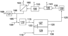
- the anode exhaust can be subjected to a variety of gas processing options, including water-gas shift and separation of the components from each other. Two general anode processing schemes are shown in FIGS. 1 and 2 .
- Fuel stream 105 can preferably include a reformable fuel, such as methane, other hydrocarbons, and/or other hydrocarbon-like compounds such as organic compounds containing carbon-hydrogen bonds. Fuel stream 105 can also optionally contain H 2 and/or CO, such as H 2 and/or CO provided by optional anode recycle stream 185 . It is noted that anode recycle stream 185 is optional, and that in many aspects no recycle stream is provided from the anode exhaust 125 back to anode 127 , either directly or indirectly via combination with fuel stream 105 or reformed fuel stream 115 . After reforming, the reformed fuel stream 115 can be passed into anode 127 of fuel cell 120 .
- a reformable fuel such as methane, other hydrocarbons, and/or other hydrocarbon-like compounds such as organic compounds containing carbon-hydrogen bonds.
- Fuel stream 105 can also optionally contain H 2 and/or CO, such as H 2 and/or CO provided by optional anode recycle stream 185 . It is noted that ano
- a CO 2 and O 2 -containing stream 119 can also be passed into cathode 129 .
- a flow of carbonate ions 122 , CO 3 2 ⁇ , from the cathode portion 129 of the fuel cell can provide the remaining reactant needed for the anode fuel cell reactions.
- the resulting anode exhaust 125 can include H 2 O, CO 2 , one or more components corresponding to incompletely reacted fuel (H 2 , CO, CH 4 , or other components corresponding to a reformable fuel), and optionally one or more additional nonreactive components, such as N 2 and/or other contaminants that are part of fuel stream 105 .
- the anode exhaust 125 can then be passed into one or more separation stages.
- a CO 2 removal stage 140 can correspond to a cryogenic CO 2 removal system, an amine wash stage for removal of acid gases such as CO 2 , or another suitable type of CO 2 separation stage for separating a CO 2 output stream 143 from the anode exhaust.
- the anode exhaust can first be passed through a water gas shift reactor 130 to convert any CO present in the anode exhaust (along with some H 2 O) into CO 2 and H 2 in an optionally water gas shifted anode exhaust 135 .
- a water condensation or removal stage 150 may be desirable to remove a water output stream 153 from the anode exhaust. Though shown in FIG.
- Stream 166 could additionally or alternately be shifted in a second water-gas shift reactor 131 to adjust the H 2 , CO, and CO 2 content to a different ratio, producing an output stream 168 for further use in a chemical synthesis process.
- FIG. 1 After the CO 2 separation stage 140 , it may optionally be located before the CO 2 separation stage 140 instead.
- an optional membrane separation stage 160 for separation of H 2 can be used to generate a high purity permeate stream 163 of H 2 .
- the resulting retentate stream 166 can then be used as an input to a chemical synthesis process.
- Stream 166 could additionally or alternately be shifted in a second water-gas shift reactor 131 to adjust the H 2 , CO, and CO 2 content to a different ratio, producing an output stream 168 for further use in a chemical synthesis process.
- FIG. 1 after the CO 2 separation stage 140 , it may optionally be located before the CO 2 separation stage 140 instead.
- an optional membrane separation stage 160 for separation of H 2 can be used
- anode recycle stream 185 is shown as being withdrawn from the retentate stream 166 , but the anode recycle stream 185 could additionally or alternately be withdrawn from other convenient locations in or between the various separation stages.
- the separation stages and shift reactor(s) could additionally or alternately be configured in different orders, and/or in a parallel configuration.
- a stream with a reduced content of CO 2 139 can be generated as an output from cathode 129 .
- various stages of compression and heat addition/removal that might be useful in the process, as well as steam addition or removal, are not shown.
- FIG. 2 shows an example of an alternative order for performing separations on an anode exhaust.
- anode exhaust 125 can be initially passed into separation stage 260 for removing a portion 263 of the hydrogen content from the anode exhaust 125 .
- This can allow, for example, reduction of the H 2 content of the anode exhaust to provide a retentate 266 with a ratio of H 2 to CO closer to 2:1.
- the ratio of H 2 to CO can then be further adjusted to achieve a desired value in a water gas shift stage 230 .
- the water gas shifted output 235 can then pass through CO 2 separation stage 240 and water removal stage 250 to produce an output stream 275 suitable for use as an input to a desired chemical synthesis process.
- output stream 275 could be exposed to an additional water gas shift stage (not shown).
- a portion of output stream 275 can optionally be recycled (not shown) to the anode input.
- still other combinations and sequencing of separation stages can be used to generate a stream based on the anode output that has a desired composition. For the sake of simplicity, various stages of compression and heat addition/removal that might be useful in the process, as well as steam addition or removal, are not shown.
- a molten carbonate fuel cell can be operated based on drawing a desired load while consuming some portion of the fuel in the fuel stream delivered to the anode.
- the voltage of the fuel cell can then be determined by the load, fuel input to the anode, air and CO 2 provided to the cathode, and the internal resistances of the fuel cell.
- the CO 2 to the cathode can be conventionally provided in part by using the anode exhaust as at least a part of the cathode input stream.
- the present invention can use separate/different sources for the anode input and cathode input.
- an MCFC can be operated to cause alternative ion transport across the electrolyte for the fuel cell.
- the CO 2 content of the cathode input stream can be 5.0 vol % or less, or 4.0 vol % or less, such as 1.5 vol % to 5.0 vol %, or 1.5 vol % to 4.0 vol %, or 2.0 vol % to 5.0 vol %, or 2.0 vol % to 4.0 vol %.
- combustion sources include, but are not limited to, sources based on combustion of natural gas, combustion of coal, and/or combustion of other hydrocarbon-type fuels (including biologically derived fuels). Additional or alternate sources can include other types of boilers, fired heaters, furnaces, and/or other types of devices that burn carbon-containing fuels in order to heat another substance (such as water or air).
- Other potential sources for a cathode input stream can additionally or alternately include sources of bio-produced CO 2 .
- This can include, for example, CO 2 generated during processing of bio-derived compounds, such as CO 2 generated during ethanol production.
- An additional or alternate example can include CO 2 generated by combustion of a bio-produced fuel, such as combustion of lignocellulose.
- Still other additional or alternate potential CO 2 sources can correspond to output or exhaust streams from various industrial processes, such as CO 2 -containing streams generated by plants for manufacture of steel, cement, and/or paper.
- CO 2 -containing streams from a fuel cell can correspond to a cathode output stream from a different fuel cell, an anode output stream from a different fuel cell, a recycle stream from the cathode output to the cathode input of a fuel cell, and/or a recycle stream from an anode output to a cathode input of a fuel cell.
- an MCFC operated in standalone mode under conventional conditions can generate a cathode exhaust with a CO 2 concentration of at least about 5 vol %.
- Such a CO 2 -containing cathode exhaust could be used as a cathode input for an MCFC operated according to an aspect of the invention. More generally, other types of fuel cells that generate a CO 2 output from the cathode exhaust can additionally or alternately be used, as well as other types of CO 2 -containing streams not generated by a “combustion” reaction and/or by a combustion-powered generator. Optionally but preferably, a CO 2 -containing stream from another fuel cell can be from another molten carbonate fuel cell.
- the output from the cathode for a first molten carbonate fuel cell can be used as the input to the cathode for a second molten carbonate fuel cell.
- a cathode input stream can include O 2 to provide the components necessary for the cathode reaction.
- Some cathode input streams can be based on having air as a component.
- a combustion exhaust stream can be formed by combusting a hydrocarbon fuel in the presence of air.
- Such a combustion exhaust stream, or another type of cathode input stream having an oxygen content based on inclusion of air can have an oxygen content of about 20 vol % or less, such as about 15 vol % or less, or about 10 vol % or less.
- the oxygen content of the cathode input stream can be at least about 4 vol %, such as at least about 6 vol %, or at least about 8 vol %.
- a cathode input stream can have a suitable content of oxygen for performing the cathode reaction. In some aspects, this can correspond to an oxygen content of about 5 vol % to about 15 vol %, such as from about 7 vol % to about 9 vol %.
- the combined amount of CO 2 and O 2 can correspond to less than about 21 vol % of the input stream, such as less than about 15 vol % of the stream or less than about 10 vol % of the stream.
- An air stream containing oxygen can be combined with a CO 2 source that has low oxygen content.
- the exhaust stream generated by burning coal may include a low oxygen content that can be mixed with air to form a cathode inlet stream.
- a cathode input stream can also be composed of inert/nonreactive species such as N 2 , H 2 O, and other typical oxidant (air) components.
- inert/nonreactive species such as N 2 , H 2 O, and other typical oxidant (air) components.
- the exhaust gas can include typical components of air such as N 2 , H 2 O, and other compounds in minor amounts that are present in air.
- additional species present after combustion based on the fuel source may include one or more of H 2 O, oxides of nitrogen (NOx) and/or sulfur (SOx), and other compounds either present in the fuel and/or that are partial or complete combustion products of compounds present in the fuel, such as CO.
- These species may be present in amounts that do not poison the cathode catalyst surfaces though they may reduce the overall cathode activity. Such reductions in performance may be acceptable, or species that interact with the cathode catalyst may be reduced to acceptable levels by known pollutant removal technologies.
- the amount of O 2 present in a cathode input stream can advantageously be sufficient to provide the oxygen needed for the cathode reaction in the fuel cell.
- the volume percentage of O 2 can advantageously be at least 0.5 times the amount of CO 2 in the exhaust.
- additional air can be added to the cathode input to provide a sufficient oxidant for the cathode reaction.
- the amount of N 2 in the cathode exhaust can be at least about 78 vol %, e.g., at least about 88 vol %, and/or about 95 vol % or less.
- the cathode input stream can additionally or alternately contain compounds that are generally viewed as contaminants, such as H 2 S or NH 3 . In other aspects, the cathode input stream can be cleaned to reduce or minimize the content of such contaminants.
- a suitable temperature for operation of an MCFC can be between about 450° C. and about 750° C., such as at least about 500° C., e.g., with an inlet temperature of about 550° C. and an outlet temperature of about 625° C.
- heat can be added to or removed from the cathode input stream, if desired, e.g., to provide heat for other processes, such as reforming the fuel input for the anode.
- the source for the cathode input stream is a combustion exhaust stream
- the combustion exhaust stream may have a temperature greater than a desired temperature for the cathode inlet. In such an aspect, heat can be removed from the combustion exhaust prior to use as the cathode input stream.
- the combustion exhaust could be at a very low temperature, for example after a wet gas scrubber on a coal-fired boiler, in which case the combustion exhaust can be below about 100° C.
- the combustion exhaust could be from the exhaust of a gas turbine operated in combined cycle mode, in which the gas can be cooled by raising steam to run a steam turbine for additional power generation. In this case, the gas can be below about 50° C. Heat can be added to a combustion exhaust that is cooler than desired.
- the anode of the fuel cell when operating an MCFC to cause alternative ion transport, can be operated at a traditional fuel utilization value of roughly 60% to 80%.
- operating the anode of the fuel cell at a relatively high fuel utilization can be beneficial for improving electrical efficiency (i.e., electrical energy generated per unit of chemical energy consumed by the fuel cell).
- This can be beneficial, for example, if it is desirable to consume excess heat generated in the fuel cell (or fuel cell stack) by performing additional reforming and/or performing another endothermic reaction.
- a molten carbonate fuel cell can be operated to provide increased production of syngas and/or hydrogen.
- the heat required for performing the endothermic reforming reaction can be provided by the exothermic electrochemical reaction in the anode for electricity generation.
- this excess heat can be used in situ as a heat source for reforming and/or another endothermic reaction. This can result in more efficient use of the heat energy and/or a reduced need for additional external or internal heat exchange. This efficient production and use of heat energy, essentially in-situ, can reduce system complexity and components while maintaining advantageous operating conditions.
- the amount of reforming or other endothermic reaction can be selected to have an endothermic heat requirement comparable to, or even greater than, the amount of excess heat generated by the exothermic reaction(s) rather than significantly less than the heat requirement typically described in the prior art.
- the fuel cell can be operated so that the temperature differential between the anode inlet and the anode outlet can be negative rather than positive.
- a sufficient amount of reforming and/or other endothermic reaction can be performed to cause the output stream from the anode outlet to be cooler than the anode inlet temperature.
- additional fuel can be supplied to a heater for the fuel cell and/or an internal reforming stage (or other internal endothermic reaction stage) so that the temperature differential between the anode input and the anode output can be smaller than the expected difference based on the relative demand of the endothermic reaction(s) and the combined exothermic heat generation of the cathode combustion reaction and the anode reaction for generating electrical power.
- reforming is used as the endothermic reaction
- operating a fuel cell to reform excess fuel can allow for production of increased synthesis gas and/or increased hydrogen relative to conventional fuel cell operation while minimizing the system complexity for heat exchange and reforming.
- the additional synthesis gas and/or additional hydrogen can then be used in a variety of applications, including chemical synthesis processes and/or collection/repurposing of hydrogen for use as a “clean” fuel.
- the amount of heat generated per mole of hydrogen oxidized by the exothermic reaction at the anode can be substantially larger than the amount of heat consumed per mole of hydrogen generated by the reforming reaction.
- This quantity of energy can alternatively be expressed as the current density (current per unit area) for the cell multiplied by the difference between the theoretical maximum voltage of the fuel cell and the actual voltage, or ⁇ current density>*(Vmax ⁇ Vact).
- This quantity of energy is defined as the “waste heat” for a fuel cell.
- this excess heat can result in a substantial temperature difference from anode inlet to anode outlet.
- the excess heat can be consumed by performing a matching amount of the reforming reaction.
- the excess heat generated in the anode can be supplemented with the excess heat generated by the combustion reaction in the fuel cell. More generally, the excess heat can be consumed by performing an endothermic reaction in the fuel cell anode and/or in an endothermic reaction stage heat integrated with the fuel cell.
- the amount of reforming and/or other endothermic reaction can be selected relative to the amount of hydrogen reacted in the anode in order to achieve a desired thermal ratio for the fuel cell.
- the “thermal ratio” is defined as the heat produced by exothermic reactions in a fuel cell assembly (including exothermic reactions in both the anode and cathode) divided by the endothermic heat demand of reforming reactions occurring within the fuel cell assembly.
- the thermal ratio (TH) Q EX /Q EN , where Q EX is the sum of heat produced by exothermic reactions and Q EN is the sum of heat consumed by the endothermic reactions occurring within the fuel cell.
- the heat produced by the exothermic reactions can correspond to any heat due to reforming reactions, water gas shift reactions, combustion reactions (i.e., oxidation of fuel compounds) in the cathode, and/or the electrochemical reactions in the cell.
- the heat generated by the electrochemical reactions can be calculated based on the ideal electrochemical potential of the fuel cell reaction across the electrolyte minus the actual output voltage of the fuel cell.
- the ideal electrochemical potential of the reaction in an MCFC is believed to be about 1.04 V based on the net reaction that occurs in the cell.
- the cell can typically have an output voltage less than 1.04 V due to various losses.
- a common output/operating voltage can be about 0.7 V.
- the heat generated can be equal to the electrochemical potential of the cell (i.e. ⁇ 1.04 V) minus the operating voltage.
- the heat produced by the electrochemical reactions in the cell can be ⁇ 0.34 V when the output voltage of ⁇ 0.7 V is attained in the fuel cell.
- the electrochemical reactions would produce ⁇ 0.7 V of electricity and ⁇ 0.34 V of heat energy.
- the ⁇ 0.7 V of electrical energy is not included as part of Q EX . In other words, heat energy is not electrical energy.
- a thermal ratio can be determined for any convenient fuel cell structure, such as a fuel cell stack, an individual fuel cell within a fuel cell stack, a fuel cell stack with an integrated reforming stage, a fuel cell stack with an integrated endothermic reaction stage, or a combination thereof.
- the thermal ratio may also be calculated for different units within a fuel cell stack, such as an assembly of fuel cells or fuel cell stacks.
- the thermal ratio may be calculated for a fuel cell (or a plurality of fuel cells) within a fuel cell stack along with integrated reforming stages and/or integrated endothermic reaction stage elements in sufficiently close proximity to the fuel cell(s) to be integrated from a heat integration standpoint.
- a characteristic width in a fuel cell stack can be the height of an individual fuel cell stack element. It is noted that the separate reforming stage and/or a separate endothermic reaction stage could have a different height in the stack than a fuel cell. In such a scenario, the height of a fuel cell element can be used as the characteristic height.
- an integrated endothermic reaction stage can be defined as a stage heat integrated with one or more fuel cells, so that the integrated endothermic reaction stage can use the heat from the fuel cells as a heat source for reforming. Such an integrated endothermic reaction stage can be defined as being positioned less than 10 times the height of a stack element from fuel cells providing heat to the integrated stage.
- an integrated endothermic reaction stage (such as a reforming stage) can be positioned less than 10 times the height of a stack element from any fuel cells that are heat integrated, or less than 8 times the height of a stack element, or less than 5 times the height of a stack element, or less than 3 times the height of a stack element.
- an integrated reforming stage and/or integrated endothermic reaction stage that represents an adjacent stack element to a fuel cell element is defined as being about one stack element height or less away from the adjacent fuel cell element.
- a thermal ratio of about 1.3 or less, or about 1.15 or less, or about 1.0 or less, or about 0.95 or less, or about 0.90 or less, or about 0.85 or less, or about 0.80 or less, or about 0.75 of less, can be lower than the thermal ratio typically sought in use of MCFC fuel cells.
- the thermal ratio can be reduced to increase and/or optimize syngas generation, hydrogen generation, generation of another product via an endothermic reaction, or a combination thereof.
- the operation of the fuel cells can be characterized based on a thermal ratio.
- a molten carbonate fuel cell can be operated to have a thermal ratio of about 1.5 or less, for example about 1.3 or less, or about 1.15 or less, or about 1.0 or less, or about 0.95 or less, or about 0.90 or less, or about 0.85 or less, or about 0.80 or less, or about 0.75 or less.
- the thermal ratio can be at least about 0.25, or at least about 0.35, or at least about 0.45, or at least about 0.50.
- the fuel cell can be operated to have a temperature rise between anode input and anode output of about 40° C. or less, such as about 20° C. or less, or about 10° C. or less. Still further additionally or alternately, the fuel cell can be operated to have an anode outlet temperature that is from about 10° C. lower to about 10° C. higher than the temperature of the anode inlet. Yet further additionally or alternately, the fuel cell can be operated to have an anode inlet temperature greater than the anode outlet temperature, such as at least about 5° C. greater, or at least about 10° C. greater, or at least about 20° C. greater, or at least about 25° C. greater.
- the fuel cell can be operated to have an anode inlet temperature greater than the anode outlet temperature by about 100° C. or less, or about 80° C. or less, or about 60° C. or less, or about 50° C. or less, or about 40° C. or less, or about 30° C. or less, or about 20° C. or less.
- a temperature drop across the fuel cell can cause a temperature drop across the fuel cell.
- the amount of reforming and/or other endothermic reaction may be limited so that a temperature drop from the anode inlet to the anode outlet can be about 100° C. or less, such as about 80° C. or less, or about 60° C. or less, or about 50° C. or less, or about 40° C. or less, or about 30° C. or less, or about 20° C. or less.
- Limiting the temperature drop from the anode inlet to the anode outlet can be beneficial, for example, for maintaining a sufficient temperature to allow complete or substantially complete conversion of fuels (by reforming) in the anode.
- additional heat can be supplied to the fuel cell (such as by heat exchange or combustion of additional fuel) so that the anode inlet temperature is greater than the anode outlet temperature by less than about 100° C. or less, such as about 80° C. or less, or about 60° C. or less, or about 50° C. or less, or about 40° C. or less, or about 30° C. or less, or about 20° C. or less, due to a balancing of the heat consumed by the endothermic reaction and the additional external heat supplied to the fuel cell.
- the amount of reforming can additionally or alternately be dependent on the availability of a reformable fuel. For example, if the fuel only comprised H 2 , no reformation would occur because H 2 is already reformed and is not further reformable.
- the amount of “syngas produced” by a fuel cell can be defined as a difference in the lower heating value (LHV) value of syngas in the anode input versus an LHV value of syngas in the anode output.
- Syngas produced LHV (sg net) (LHV(sg out) ⁇ LHV(sg in)), where LHV(sg in) and LHV(sg out) refer to the LHV of the syngas in the anode inlet and syngas in the anode outlet streams or flows, respectively.
- a fuel cell provided with a fuel containing substantial amounts of H 2 can be limited in the amount of potential syngas production, since the fuel contains substantial amounts of already reformed H 2 , as opposed to containing additional reformable fuel.
- the lower heating value is defined as the enthalpy of combustion of a fuel component to vapor phase, fully oxidized products (i.e., vapor phase CO 2 and H 2 O product).
- any CO 2 present in an anode input stream does not contribute to the fuel content of the anode input, since CO 2 is already fully oxidized.
- the amount of oxidation occurring in the anode due to the anode fuel cell reaction is defined as oxidation of H 2 in the anode as part of the electrochemical reaction in the anode.
- An example of a method for operating a fuel cell with a reduced thermal ratio can be a method where excess reforming of fuel is performed in order to balance the generation and consumption of heat in the fuel cell and/or consume more heat than is generated. Reforming a reformable fuel to form H 2 and/or CO can be an endothermic process, while the anode electrochemical oxidation reaction and the cathode combustion reaction(s) can be exothermic. During conventional fuel cell operation, the amount of reforming needed to supply the feed components for fuel cell operation can typically consume less heat than the amount of heat generated by the anode oxidation reaction.
- conventional operation at a fuel utilization of about 70% or about 75% produces a thermal ratio substantially greater than 1, such as a thermal ratio of at least about 1.4 or greater, or 1.5 or greater.
- the output streams for the fuel cell can be hotter than the input streams.
- the amount of fuel reformed in the reforming stages associated with the anode can be increased.
- additional fuel can be reformed so that the heat generated by the exothermic fuel cell reactions can either be (roughly) balanced by the heat consumed in reforming and/or consume more heat than is generated.
- Either hydrogen or syngas can be withdrawn from the anode exhaust as a chemical energy output.
- Hydrogen can be used as a clean fuel without generating greenhouse gases when it is burned or combusted. Instead, for hydrogen generated by reforming of hydrocarbons (or hydrocarbonaceous compounds), the CO 2 will have already been “captured” in the anode loop. Additionally, hydrogen can be a valuable input for a variety of refinery processes and/or other synthesis processes. Syngas can also be a valuable input for a variety of processes. In addition to having fuel value, syngas can be used as a feedstock for producing other higher value products, such as by using syngas as an input for Fischer-Tropsch synthesis and/or methanol synthesis processes.
- the reformable hydrogen content of reformable fuel in the input stream delivered to the anode and/or to a reforming stage associated with the anode can be at least about 50% greater than the net amount of hydrogen reacted at the anode, such as at least about 75% greater or at least about 100% greater. Additionally or alternately, the reformable hydrogen content of fuel in the input stream delivered to the anode and/or to a reforming stage associated with the anode can be at least about 50% greater than the net amount of hydrogen reacted at the anode, such as at least about 75% greater or at least about 100% greater.
- a ratio of the reformable hydrogen content of the reformable fuel in the fuel stream relative to an amount of hydrogen reacted in the anode can be at least about 1.5:1, or at least about 2.0:1, or at least about 2.5:1, or at least about 3.0:1. Additionally or alternately, the ratio of reformable hydrogen content of the reformable fuel in the fuel stream relative to the amount of hydrogen reacted in the anode can be about 20:1 or less, such as about 15:1 or less or about 10:1 or less. In one aspect, it is contemplated that less than 100% of the reformable hydrogen content in the anode inlet stream can be converted to hydrogen.
- the amount of reformable fuel delivered to the anode can be characterized based on the Lower Heating Value (LHV) of the reformable fuel relative to the LHV of the hydrogen oxidized in the anode.
- LHV Lower Heating Value
- the reformable fuel surplus ratio can be at least about 2.0, such as at least about 2.5, or at least about 3.0, or at least about 4.0.
- the reformable fuel surplus ratio can be about 25.0 or less, such as about 20.0 or less, or about 15.0 or less, or about 10.0 or less.
- the cathode is typically operated with a CO 2 concentration in the cathode input feed of 8 vol % or more and/or a CO 2 utilization of 70% or less. Such operation typically corresponds to a cathode exhaust that includes 5.0 vol % or more CO 2 .
- the anode is operated with an excess of fuel at a fuel utilization of 60% or more.
- reforming catalyst patterns have been developed in order to improve fuel cell operation. These catalyst patterns are based on an expected temperature profile during conventional fuel cell operation. The expected temperature profile is based on a corresponding expectation of where the reaction will occur within a fuel cell.
- FIG. 5 shows an example of a flow pattern within a reforming element.
- the reformable fuel 521 is initially passed through a channel 530 on the side of the reforming element 510 .
- the channel 530 is in proximity to the cathode inlet of the fuel cell stack.
- the channel 530 is separated from a remaining or first portion of reforming element 510 by a barrier 535 .
- the catalyst density in channel 530 can be relatively uniform, such as due to having no reforming catalyst in channel 530 .
- channel 530 can have a non-zero reforming catalyst density, such as reforming catalyst density corresponding to the average reforming catalyst density in the first portion 540 , the minimum catalyst density in first portion 540 , or any other convenient catalyst density.
- reforming catalyst density corresponding to the average reforming catalyst density in the first portion 540 , the minimum catalyst density in first portion 540 , or any other convenient catalyst density.
- the reformable fuel 521 is passed 545 from channel 530 to first portion 540 of reforming element 510 , where it flows through first portion 540 in the direction of arrow 508 .
- the hydrogen produced by reforming and/or remaining portions of unreformed fuel can then exit the reforming element (not shown) and be passed into one or more anodes (via anode collectors) by any convenient method, such as via one or more manifolds or conduits.
- Arrow 550 shows the direction of flow within an anode associated with the reforming element 510
- arrow 560 shows the direction of flow within a cathode associated with the reforming element 510 .
- FIG. 6 shows an example of a reforming catalyst pattern suitable for use on a surface that includes reforming catalyst.
- the catalyst pattern is formed based on parallel lines of catalyst particles, with the direction of flow being substantially parallel the lines of catalyst particles during most portions of the flow path.
- the pattern shown in FIG. 6 corresponds to a pattern suitable either for the reforming catalyst in the entire reforming element, or alternatively for a portion such as first portion 510 in a reforming element.
- the reforming catalyst density is highest at the left end, and decreases to no catalyst density at the right end.
- the reforming catalyst pattern shown in FIG. 6 corresponds to having an elevated concentration of reforming catalyst near the anode inlet and little or no reforming catalyst near the anode exit.
- the catalyst pattern in FIG. 6 can provide substantial reforming in proximity to both the anode inlet and the cathode inlet.
- U.S. Pat. No. 8,822,090 describes another type of reforming catalyst pattern.
- two separate catalyst density variations are present, with one being aligned with the cathode flow and the other being aligned with the anode flow.
- the fuel enters the reforming element on a side that is in proximity to the cathode outlet side of the fuel cell stack.
- the catalyst density increases as the fuel moves from the cathode outlet side of the reforming element toward the cathode outlet side.
- An example of a catalyst pattern is shown with variations in reforming catalyst density based on placement of reforming catalyst particles.
- the maximum catalyst density corresponds to placement of particles with a frequency of one particle per two potential placement sites and a minimum catalyst density of one particle per sixty-four potential placement sites. This corresponds to a variation from maximum to minimum of over 90%, under the definitions provided herein. It is noted that in addition to the variation along the direction of cathode flow, there is a second gradient along the direction of anode flow in the anode associated with the reforming element.
- a molten carbonate fuel cell model that included aspects to represent fluid flows and heat transfer within the fuel cell was used to determine the impact of catalyst pattern on temperature differences within the fuel cell.
- the model was constructed using a commercially available process modeling platform.
- the model represented a system with a reforming element, an associated fuel cell having an anode and a cathode, and a separator plate between the reforming element and the associated fuel cell.
- the flow pattern in the reforming element corresponds to the flow pattern shown in FIG. 5 .
- the reforming element included an initial channel in proximity to the cathode inlet with a constant catalyst density (corresponding to the average in the first portion), and a first portion with a catalyst pattern that was aligned with the flow pattern in the anode.
- modeling results are provided for molten carbonate fuel cells with two different types of catalyst patterns for a first portion of the reforming element.
- One type of catalyst pattern corresponds to the catalyst pattern shown in FIG. 5 .
- a second type of catalyst pattern corresponds to a catalyst pattern with a difference between maximum and minimum catalyst density of roughly 63%.
- FIG. 7 shows three types of catalyst density profiles for a first portion of a reforming element.
- the x-axis corresponds to the flow axis in the anode, with 0 corresponding to the anode inlet and 1 corresponding to the anode outlet.
- Line 910 corresponds to the conventional catalyst profile shown in FIG. 5 .
- Line 920 corresponds to the catalyst profile used for the second fuel cell that was modeled. As shown in FIG. 7 , line 920 has a ratio of minimum to maximum catalyst density of 60/160, or 3/8. This corresponds to a difference between maximum and minimum of 62.5%. By contrast, the difference between maximum and minimum for line 910 is effectively 100%, as the catalyst density drops to zero at the anode outlet in line 910 .
- FIG. 7 also shows line 930 , which is similar to the profile in line 920 , but with a continuous monotonic decrease in catalyst density, as opposed to the step-wise monotonic decrease in catalyst density shown in line 920 .
- FIG. 8 shows the temperature variation at the separator plate for the fuel cell that was modeled with the comparative reforming catalyst density corresponding to line 910 of FIG. 7 .
- the x-axis corresponds to the anode flow direction
- the y-axis corresponds to the cathode flow direction.
- the temperature gradient across the fuel cell is greater than 80° K, or greater than 80° C. This is due to the excess waste heat generated by alternative ion transport in the corner of the fuel cell corresponding to the cathode outlet and the anode outlet.
- the catalyst density is close to zero near the corner corresponding to the cathode outlet and anode outlet. Thus, there is only a minimal amount of the endothermic reforming reaction available to balance the additional waste heat generated due to alternative ion transport.
- FIG. 9 shows the temperature variation at the separator plate for the fuel cell that was modeled with the reforming catalyst density corresponding to line 920 of FIG. 7 .
- a molten carbonate fuel cell model that included aspects to represent fluid flows and heat transfer within the fuel cell was used to determine the impact of catalyst pattern on temperature differences within the fuel cell.
- the model was constructed using a commercially available process modeling platform.
- the model represented a system with a reforming element, an associated fuel cell having an anode and a cathode, and a separator plate between the reforming element and the associated fuel cell.
- the flow pattern in the reforming element corresponds to the flow pattern shown in FIG. 5 .
- the reforming element included an initial channel in proximity to the cathode inlet with a constant catalyst density (corresponding to the average in the first portion), and a first portion with a catalyst pattern that was aligned with the flow pattern in the anode.
- modeling results are provided for molten carbonate fuel cells with three different types of catalyst patterns for a first portion of the reforming element.
- One type of catalyst pattern corresponds to the catalyst pattern shown in FIG. 5 .
- a second type of catalyst pattern corresponds to a catalysts pattern with a difference between maximum and minimum catalyst density of roughly 100%, like the first type of catalyst pattern in this example.
- a third type of catalyst pattern corresponds to a catalyst pattern with a difference between maximum and minimum catalyst density of roughly 43%.
- FIG. 10 shows four types of catalyst density profiles for a first portion of a reforming element.
- the x-axis corresponds to the flow axis in the anode, with 0 corresponding to the anode inlet and 1 corresponding to the anode outlet.
- Line 910 corresponds to the conventional catalyst profile shown in FIG. 5 and in FIG. 7 from Example 2 above. As noted above, the difference between maximum and minimum catalyst density for this catalyst profile is effectively 100%, as the catalyst density drops to zero at the anode outlet in line 910 .
- line 1010 corresponds to another catalyst profile having a difference between maximum and minimum catalyst density as effectively 100%, since here too, the catalyst density drops to zero at the anode outlet in line 1010 . As shown in FIG.
- line 1020 has a ratio of minimum to maximum catalyst density of approximately 80/160, or 1/2. This corresponds to a difference between maximum and minimum of approximately 50%.
- FIG. 10 also shows line 1030 , which is similar to the profile in line 1020 , but with a continuous monotonic decrease in catalyst density, as opposed to the step-wise monotonic decrease in catalyst density shown in line 1020 .
- fuel cells using the catalyst profiles described by line 1010 for the first portion of the surface in the reforming element were modeled under conditions that resulted in elevated CO 2 utilization.
- the model conditions were a cathode inlet CO 2 concentration of 4.3 vol %, a fuel utilization of 50%, an actual CO 2 utilization of ⁇ 85%, an average cathode temperature of roughly 903.15° K (630° C.), and a current density of 110 mA/cm 2 .
- the input stream into the reformer included 7 vol % H 2 , 2 vol % CO 2 , 60 vol % H 2 O, and 30 vol % CH 4 , with the balance corresponding to nitrogen.
- fuel cells using the catalyst profiles described by line 1020 for the first portion of the surface in the reforming element were modeled under conditions that resulted in elevated CO 2 utilization.
- the model conditions were a cathode inlet CO 2 concentration of 4.4 vol %, a fuel utilization of 50%, an actual CO 2 utilization of ⁇ 85%, an average cathode temperature of roughly 903.15° K (630° C.), and a current density of 150 mA/cm 2 .
- the input stream into the reformer included 10 vol % H 2 , 3 vol % CO 2 , 58% H 2 O, and 29 vol % CH 4 with the balance corresponding to nitrogen.
- FIG. 11 shows the temperature variation at the separator plate for the fuel cell that was modeled with the comparative reforming catalyst density corresponding to line 910 of FIG. 10 .
- the x-axis corresponds to the anode flow direction
- the y-axis corresponds to the cathode flow direction.
- the temperature gradient across the fuel cell is greater than 100° K, or greater than 100° C. This is due to the excess waste heat generated by alternative ion transport in the corner of the fuel cell corresponding to the cathode outlet and the anode outlet.
- the catalyst density is close to zero near the corner corresponding to the cathode outlet and anode outlet. Thus, there is only a minimal amount of the endothermic reforming reaction available to balance the additional waste heat generated due to alternative ion transport.
- FIG. 12 shows the temperature variation of the separator plate for the fuel cell that was modeled with the reforming catalyst density corresponding to line 1010 of FIG. 10 .
- the temperature gradient across the fuel cell is approximately 70° K or 70° C., which is due to the excess waste heat generated by alternative ion transport in the corner of the fuel cell corresponding to the cathode outlet and the anode outlet.
- the catalyst density is close to zero near the corner corresponding to the cathode outlet and anode outlet.
- FIG. 13 shows the temperature variation at the separator plate for the fuel cell that was modeled with the reforming catalyst density corresponding to line 1030 of FIG. 10 .
- Embodiment 1 A method for producing electricity, the method comprising: passing a fuel stream comprising a reformable fuel into a fuel stack comprising a first surface, the first surface comprising a first portion comprising a reforming catalyst, a reforming catalyst density on the first portion of the first surface having a difference between a maximum catalyst density and a minimum catalyst density of 20% to 75%; reforming at least a portion of the reformable fuel in the presence of the first surface to produce reformed hydrogen; introducing at least a portion of the reformable fuel, at least a portion of the reformed hydrogen, or a combination thereof into an anode of a molten carbonate fuel cell; introducing a cathode input stream comprising O 2 and CO 2 into a cathode of the molten carbonate fuel cell, a direction of flow in the cathode of the molten carbonate fuel cell being substantially orthogonal to a direction of flow in the anode of the molten carbonate fuel cell; and operating the molten carbonate fuel
- Embodiment 2 The method of Embodiment 1, wherein the cathode input stream comprises 5.0 vol % or less of CO 2 , or wherein the cathode exhaust comprises 1.0 vol % or less of CO 2 , or a combination thereof.
- Embodiment 3 A method for producing electricity, the method comprising: passing a fuel stream comprising a reformable fuel into a fuel stack comprising a first surface, the first surface comprising a first portion comprising a reforming catalyst, a reforming catalyst density on the first portion of the first surface having a difference between a maximum catalyst activity and a minimum catalyst activity of 20% to 75%; reforming at least a portion of the reformable fuel in the presence of the first surface to produce reformed hydrogen; introducing at least a portion of the reformable fuel, at least a portion of the reformed hydrogen, or a combination thereof into an anode of a molten carbonate fuel cell; introducing a cathode input stream comprising O 2 and CO 2 into a cathode of the molten carbonate fuel cell, a direction of flow in the cathode of the molten carbonate fuel cell being substantially orthogonal to a direction of flow in the anode of the molten carbonate fuel cell; and operating the molten carbonate fuel
- Embodiment 4 The method of any of the above embodiments, wherein the transference is 0.95 or less, or 0.90 or less.
- Embodiment 5 The method of any of the above embodiments, wherein the reforming catalyst on the first portion of the first surface comprises a monotonic catalyst density variation.
- Embodiment 6 The method of any of the above embodiments, wherein the maximum catalyst density is in proximity to the anode inlet, or wherein the maximum catalyst density is in proximity to the cathode inlet.
- Embodiment 7 The method of any of the above embodiments, wherein the minimum catalyst density is in proximity to the anode outlet, or wherein the minimum catalyst density is in proximity to the cathode outlet.
- Embodiment 8 The method of any of the above embodiments, wherein the fuel cell stack comprises a reforming element associated with the anode, wherein the first surface comprises an interior surface of the reforming element, and wherein a temperature variation within the fuel cell stack at a separator plate between the reforming element and the anode is optionally 70° C. or less (or 40° C. or less).
- Embodiment 10 The method of any of the above embodiments, wherein the first surface further comprises a second portion, the second portion optionally comprising at least one of a constant catalyst density and a constant catalyst activity, and wherein the second portion is in proximity to the cathode inlet, or wherein the second portion is in proximity to the anode inlet.
- Embodiment 11 The method of any of the above embodiments, wherein the reforming catalyst comprises a plurality of lines of catalyst particles, and wherein reforming the at least a portion of the reformable fuel comprises flowing the at least a portion of the reformable fuel over the catalyst particles in a direction that is substantially parallel to the lines of catalyst particles.
- a fuel cell stack comprising: a molten carbonate fuel cell comprising an anode and a cathode; a reforming element associated with the anode, the reforming element comprising a first surface, the first surface comprising a first portion comprising a reforming catalyst, a reforming catalyst density on the first portion of the first surface comprising a monotonically decreasing catalyst density, the reforming catalyst density on the first portion of the first surface having a difference between a maximum catalyst density and a minimum catalyst density of 20% to 75% (or 25% to 70%, or 25% to 65%); and a separator plate between the anode and the reforming element, wherein the first surface optionally further comprises a second portion, the optional second portion being in proximity to the cathode inlet or in proximity to the anode inlet, the optional second portion comprising a constant catalyst density.
- Embodiment 13 The fuel cell stack of Embodiment 12, wherein the maximum catalyst density is in proximity to the anode inlet, or wherein the maximum catalyst density is in proximity to the cathode inlet.
- Embodiment 15 The fuel cell stack of any of Embodiments 12 to 14, wherein the reforming catalyst comprises substantially parallel lines of catalyst particles
Landscapes
- Chemical & Material Sciences (AREA)
- Chemical Kinetics & Catalysis (AREA)
- Electrochemistry (AREA)
- General Chemical & Material Sciences (AREA)
- Life Sciences & Earth Sciences (AREA)
- Engineering & Computer Science (AREA)
- Manufacturing & Machinery (AREA)
- Sustainable Development (AREA)
- Sustainable Energy (AREA)
- Fuel Cell (AREA)
- Catalysts (AREA)
Abstract
Description
Claims (18)
Priority Applications (1)
| Application Number | Priority Date | Filing Date | Title |
|---|---|---|---|
| US18/110,097 US12095129B2 (en) | 2018-11-30 | 2023-02-15 | Reforming catalyst pattern for fuel cell operated with enhanced CO2 utilization |
Applications Claiming Priority (3)
| Application Number | Priority Date | Filing Date | Title |
|---|---|---|---|
| US201862773485P | 2018-11-30 | 2018-11-30 | |
| US16/696,821 US11742508B2 (en) | 2018-11-30 | 2019-11-26 | Reforming catalyst pattern for fuel cell operated with enhanced CO2 utilization |
| US18/110,097 US12095129B2 (en) | 2018-11-30 | 2023-02-15 | Reforming catalyst pattern for fuel cell operated with enhanced CO2 utilization |
Related Parent Applications (1)
| Application Number | Title | Priority Date | Filing Date |
|---|---|---|---|
| US16/696,821 Division US11742508B2 (en) | 2018-11-30 | 2019-11-26 | Reforming catalyst pattern for fuel cell operated with enhanced CO2 utilization |
Publications (2)
| Publication Number | Publication Date |
|---|---|
| US20230197994A1 US20230197994A1 (en) | 2023-06-22 |
| US12095129B2 true US12095129B2 (en) | 2024-09-17 |
Family
ID=69005868
Family Applications (2)
| Application Number | Title | Priority Date | Filing Date |
|---|---|---|---|
| US16/696,821 Active 2040-08-14 US11742508B2 (en) | 2018-11-30 | 2019-11-26 | Reforming catalyst pattern for fuel cell operated with enhanced CO2 utilization |
| US18/110,097 Active US12095129B2 (en) | 2018-11-30 | 2023-02-15 | Reforming catalyst pattern for fuel cell operated with enhanced CO2 utilization |
Family Applications Before (1)
| Application Number | Title | Priority Date | Filing Date |
|---|---|---|---|
| US16/696,821 Active 2040-08-14 US11742508B2 (en) | 2018-11-30 | 2019-11-26 | Reforming catalyst pattern for fuel cell operated with enhanced CO2 utilization |
Country Status (4)
| Country | Link |
|---|---|
| US (2) | US11742508B2 (en) |
| JP (3) | JP7258144B2 (en) |
| KR (1) | KR102610181B1 (en) |
| WO (1) | WO2020112895A1 (en) |
Families Citing this family (8)
| Publication number | Priority date | Publication date | Assignee | Title |
|---|---|---|---|---|
| US11742508B2 (en) | 2018-11-30 | 2023-08-29 | ExxonMobil Technology and Engineering Company | Reforming catalyst pattern for fuel cell operated with enhanced CO2 utilization |
| CA3121538C (en) | 2018-11-30 | 2023-09-12 | Exxonmobile Research And Engineering Company | Method for producing electricity in a molten carbonate fuel cell |
| US11888187B2 (en) * | 2018-11-30 | 2024-01-30 | ExxonMobil Technology and Engineering Company | Operation of molten carbonate fuel cells with enhanced CO2 utilization |
| JP2023503995A (en) | 2019-11-26 | 2023-02-01 | エクソンモービル・テクノロジー・アンド・エンジニアリング・カンパニー | Fuel cell module assembly and system using same |
| CN114930589B (en) | 2019-11-26 | 2025-05-30 | 埃克森美孚技术与工程公司 | Fuel cell assembly with external manifold for parallel flow |
| US11978931B2 (en) | 2021-02-11 | 2024-05-07 | ExxonMobil Technology and Engineering Company | Flow baffle for molten carbonate fuel cell |
| FR3125649A1 (en) * | 2021-07-23 | 2023-01-27 | Technip France | Method for implementing a fuel cell system with carbon dioxide recovery and associated installation |
| WO2023202798A1 (en) * | 2022-04-21 | 2023-10-26 | Nuovo Pignone Tecnologie - S.R.L. | Low-emission power generation system and method |
Citations (403)
| Publication number | Priority date | Publication date | Assignee | Title |
|---|---|---|---|---|
| US3615839A (en) | 1968-07-12 | 1971-10-26 | United Aircraft Corp | Fuel cell system with recycle stream |
| US3970474A (en) | 1975-08-11 | 1976-07-20 | Stanford Research Institute | Method and apparatus for electrochemical generation of power from carbonaceous fuels |
| US4041210A (en) | 1976-08-30 | 1977-08-09 | United Technologies Corporation | Pressurized high temperature fuel cell power plant with bottoming cycle |
| US4160663A (en) | 1978-02-21 | 1979-07-10 | Jack Hsieh | Method for the direct reduction of iron ore |
| JPS5669775A (en) | 1979-11-12 | 1981-06-11 | Hitachi Ltd | Generation of molten-carbonate fuel cell |
| JPS5893170A (en) | 1981-11-26 | 1983-06-02 | Toshiba Corp | Molten carbonate type fuel cell |
| US4389467A (en) | 1979-12-27 | 1983-06-21 | The United States Of America As Represented By The United States Department Of Energy | Porous electrolyte retainer for molten carbonate fuel cell |
| US4449994A (en) | 1982-01-15 | 1984-05-22 | Air Products And Chemicals, Inc. | Low energy process for separating carbon dioxide and acid gases from a carbonaceous off-gas |
| US4476683A (en) | 1982-12-20 | 1984-10-16 | General Electric Company | Energy efficient multi-stage water gas shift reaction |
| US4476633A (en) | 1981-12-30 | 1984-10-16 | Heinz Brych | Pliers for punching cards or tickets |
| US4532192A (en) | 1984-11-06 | 1985-07-30 | Energy Research Corporation | Fuel cell system |
| US4567117A (en) * | 1982-07-08 | 1986-01-28 | Energy Research Corporation | Fuel cell employing non-uniform catalyst |
| EP0170277A2 (en) | 1984-07-31 | 1986-02-05 | Hitachi, Ltd. | Fuel cell power plant |
| JPS62241524A (en) | 1986-04-14 | 1987-10-22 | Kawasaki Steel Corp | Separation and purification for carbon monoxide excellent in stabilization of purity |
| US4702973A (en) | 1986-08-25 | 1987-10-27 | Institute Of Gas Technology | Dual compartment anode structure |
| US4772634A (en) | 1986-07-31 | 1988-09-20 | Energy Research Corporation | Apparatus and method for methanol production using a fuel cell to regulate the gas composition entering the methanol synthesizer |
| US4800052A (en) | 1985-12-23 | 1989-01-24 | International Fuel Cells Corporation | Method of fabricating molten carbonate cathodes |
| US4810595A (en) | 1987-01-09 | 1989-03-07 | New Energy Development Organization | Molten carbonate fuel cell, and its operation control method |
| US4828940A (en) | 1987-08-27 | 1989-05-09 | International Fuel Cells Corporation | Fuel cell power plant with increased reactant pressures |
| JPH0275164A (en) | 1988-09-08 | 1990-03-14 | Hitachi Ltd | Molten carbonate fuel cell power generation device and method of operating the power generation device |
| US4917971A (en) | 1989-03-03 | 1990-04-17 | Energy Research Corporation | Internal reforming fuel cell system requiring no recirculated cooling and providing a high fuel process gas utilization |
| US4921765A (en) | 1989-06-26 | 1990-05-01 | The United States Of America As Represented By The United States Department Of Energy | Combined goal gasifier and fuel cell system and method |
| US4925745A (en) | 1985-03-29 | 1990-05-15 | Institute Of Gas Technoloy | Sulfur tolerant molten carbonate fuel cell anode and process |
| JPH02281569A (en) | 1989-04-21 | 1990-11-19 | Hitachi Ltd | Molten carbonate fuel cell power plant |
| JPH031447A (en) | 1988-09-08 | 1991-01-08 | Internatl Fuel Cells Corp | Fuel cell |
| US4983472A (en) | 1989-11-24 | 1991-01-08 | International Fuel Cells Corporation | Fuel cell current collector |
| US4995807A (en) | 1989-03-20 | 1991-02-26 | Bryan Steam Corporation | Flue gas recirculation system |
| US5039579A (en) | 1988-12-24 | 1991-08-13 | Ishikawajima-Harima Heavy Industries Co., Ltd. | Electric power producing system using molten carbonate type fuel cell |
| DE4005468A1 (en) | 1990-02-21 | 1991-08-22 | Linde Ag | Operation of high temp. fuel cells - using ion-conducting electrolytes, removing cathode and anode off-gases produced and recycling anode off-gas |
| JPH03210774A (en) | 1990-01-11 | 1991-09-13 | Kansai Electric Power Co Inc:The | Internally improved quality system molten carbonate type fuel cell |
| US5071719A (en) | 1989-11-20 | 1991-12-10 | Haldor Topsoe A/S | Fuel cell power plant |
| US5079103A (en) | 1989-04-25 | 1992-01-07 | Linde Aktiengesellschaft | Fuel cells with hydrogen recycle |
| US5082752A (en) | 1989-11-25 | 1992-01-21 | Ishikawajima-Harima Heavy Industries Co., Ltd. | Power generation system using molten carbonate fuel cell |
| US5084362A (en) | 1990-08-29 | 1992-01-28 | Energy Research Corporation | Internal reforming molten carbonate fuel cell system with methane feed |
| JPH0439868A (en) | 1990-06-06 | 1992-02-10 | Ishikawajima Harima Heavy Ind Co Ltd | Separator for molten carbonate fuel cells |
| US5134043A (en) | 1990-02-15 | 1992-07-28 | Ishikawajima-Harima Heavy Industries Co., Ltd. | Operation method for power generation system using fuel cell |
| CN2120858U (en) | 1992-05-25 | 1992-11-04 | 赵辰晖 | Two-side open-close device for door and window with slide cross moving |
| JPH04334870A (en) | 1991-05-13 | 1992-11-20 | Mitsubishi Electric Corp | Fused carbonate type fuel cell generating set |
| US5169717A (en) | 1988-07-01 | 1992-12-08 | Haldor Topsoe A/S | Method of preparing ammonia |
| JPH0529009A (en) | 1991-07-18 | 1993-02-05 | Matsushita Electric Ind Co Ltd | Gas channel plate for fuel cell |
| US5198311A (en) | 1990-05-30 | 1993-03-30 | Ishikawajima-Harima Heavy Industries Co., Ltd. | Lng cryogenic power generation system using molten carbonate fuel cells |
| US5208113A (en) | 1991-07-10 | 1993-05-04 | Ishikawajima-Harima Heavy Industries Co., Ltd. | Power generation method using molten carbonate fuel cells |
| JPH05163180A (en) | 1991-12-16 | 1993-06-29 | Ishikawajima Harima Heavy Ind Co Ltd | Methanol synthesis using hydrocarbon gas as raw material |
| US5232793A (en) | 1989-09-19 | 1993-08-03 | Ishikawajima-Harima Heavy Industries Co., Ltd. | Method of and apparatus for utilizing and recovering co2 in combustion exhaust gas |
| JPH05325996A (en) | 1992-05-22 | 1993-12-10 | Matsushita Electric Ind Co Ltd | Internal reforming molten carbonate fuel cell |
| JPH06196184A (en) | 1992-10-30 | 1994-07-15 | Sekiyu Sangyo Kasseika Center | Catalyst filling device for fuel cell |
| CA2120858A1 (en) | 1993-04-26 | 1994-10-27 | Ramachandran Krishnamurthy | Enhanced recovery of carbon dioxide from kiln gas by addition of cooled carbon dioxide |
| US5376472A (en) | 1993-10-06 | 1994-12-27 | Ceramatec, Inc. | Semi-internally manifolded interconnect |
| US5380600A (en) | 1989-06-19 | 1995-01-10 | Haldor Topsoe A/S | Fuel cell system |
| US5413878A (en) | 1993-10-28 | 1995-05-09 | The United States Of America As Represented By The Department Of Energy | System and method for networking electrochemical devices |
| US5417051A (en) | 1990-10-15 | 1995-05-23 | Mannesmann Aktiengesellschaft | Process and installation for the combined generation of electrical and mechanical energy |
| US5422195A (en) | 1994-05-04 | 1995-06-06 | Energy Research Corporation | Carbonate fuel cell with direct recycle of anode exhaust to cathode |
| JPH07201349A (en) | 1993-10-28 | 1995-08-04 | United States Department Of Energ | Indirect combustion type gas turbine cycle based on fuel cell cycle |
| EP0678926A1 (en) | 1994-04-19 | 1995-10-25 | FINMECCANICA S.p.A. AZIENDA ANSALDO | A method of manufacturing cathodes for fuel cells |
| US5468573A (en) | 1994-06-23 | 1995-11-21 | International Fuel Cells Corporation | Electrolyte paste for molten carbonate fuel cells |
| US5470670A (en) | 1993-03-01 | 1995-11-28 | Matsushita Electric Industrial Co., Ltd. | Fuel cell |
| EP0691701A1 (en) | 1994-07-05 | 1996-01-10 | Ishikawajima-Harima Heavy Industries Co., Ltd. | Plate reformer |
| JPH0896824A (en) | 1994-09-29 | 1996-04-12 | Ishikawajima Harima Heavy Ind Co Ltd | Molten carbonate fuel cell power generator |
| US5518828A (en) | 1994-07-21 | 1996-05-21 | Bechtel Group, Inc. | Thermal integration of an air-cooled fuel cell stack |
| US5518827A (en) | 1993-04-28 | 1996-05-21 | Mitsubishi Denki Kabushiki Kaisha | Internal reforming type fuel cell device and fuel cell generating system |
| JPH08138701A (en) | 1994-11-15 | 1996-05-31 | Toshiba Corp | Molten carbonate fuel cell |
| US5541014A (en) | 1995-10-23 | 1996-07-30 | The United States Of America As Represented By The United States Department Of Energy | Indirect-fired gas turbine dual fuel cell power cycle |
| US5554453A (en) | 1995-01-04 | 1996-09-10 | Energy Research Corporation | Carbonate fuel cell system with thermally integrated gasification |
| DE19515669A1 (en) | 1995-04-28 | 1996-10-31 | Ingbuero Dipl Ing Rudolf Loock | Generation of electrical energy from biomass fermentation |
| US5616430A (en) | 1994-08-30 | 1997-04-01 | Toyota Jidosha Kabushiki Kaisha | Reformer and fuel cell system using the same |
| DE19545186A1 (en) | 1995-12-04 | 1997-06-05 | Siemens Ag | Method for operating a high-temperature fuel cell system and high-temperature fuel cell system |
| US5660941A (en) | 1996-06-19 | 1997-08-26 | Energy Research Corporation | Catalyst assembly for internal reforming fuel cell |
| WO1997033828A1 (en) | 1996-03-12 | 1997-09-18 | Technische Universiteit Delft | Method for the manufacture of ammonia |
| DE19609313C1 (en) | 1996-03-09 | 1997-09-25 | Mtu Friedrichshafen Gmbh | Method for producing a cathode for a molten carbonate fuel cell and a cathode produced by the method |
| US5736026A (en) | 1996-02-05 | 1998-04-07 | Energy Research Corporation | Biomass-fuel cell cogeneration apparatus and method |
| JPH10172595A (en) | 1996-12-17 | 1998-06-26 | Ishikawajima Harima Heavy Ind Co Ltd | Method and apparatus for monitoring carbon deposition in molten carbonate fuel cell |
| US5833734A (en) | 1995-10-10 | 1998-11-10 | Voest-Alpine Industrieanlagenbau Gmbh | Process for the direct reduction of particulate iron-containing material and a plant for carrying out the process |
| JPH1191427A (en) | 1997-09-26 | 1999-04-06 | Kanto Auto Works Ltd | Cup holder |
| NL1008883C2 (en) | 1998-04-15 | 1999-10-18 | Univ Delft Tech | Production of hydrogen by high temperature conversion of hydrocarbons in the presence of water or oxygen |
| JPH11312527A (en) | 1998-04-28 | 1999-11-09 | Nippon Steel Corp | Molten carbonate fuel cell power generation-exhaust gas recovery combined system using steelmaking by-product gas |
| US6030718A (en) | 1997-11-20 | 2000-02-29 | Avista Corporation | Proton exchange membrane fuel cell power system |
| US6063515A (en) | 1997-12-22 | 2000-05-16 | Ballard Power Systems Inc. | Integrated fuel cell electric power generation system for submarine applications |
| WO2000031815A1 (en) | 1998-11-25 | 2000-06-02 | Gas Technology Institute | Sheet metal bipolar plate design for polymer electrolyte membrane fuel cells |
| US6083636A (en) | 1994-08-08 | 2000-07-04 | Ztek Corporation | Fuel cell stacks for ultra-high efficiency power systems |
| US6090312A (en) | 1996-01-31 | 2000-07-18 | Ziaka; Zoe D. | Reactor-membrane permeator process for hydrocarbon reforming and water gas-shift reactions |
| DE19941724A1 (en) | 1998-09-14 | 2000-08-31 | Forschungszentrum Juelich Gmbh | Fuel cell operated with excess fuel |
| US6126718A (en) | 1999-02-03 | 2000-10-03 | Kawasaki Steel Corporation | Method of producing a reduced metal, and traveling hearth furnace for producing same |
| US6162556A (en) | 1995-12-04 | 2000-12-19 | Siemens Aktiengesellschaft | Method for operating a high-temperature fuel cell installation, and a high-temperature fuel cell installation |
| JP2001023670A (en) | 1999-07-06 | 2001-01-26 | Mitsubishi Electric Corp | Fuel cell generator |
| US6267799B1 (en) | 1995-04-07 | 2001-07-31 | Technological Resources Pty. Ltd. | Method of producing metals and metal alloys |
| US6280865B1 (en) | 1999-09-24 | 2001-08-28 | Plug Power Inc. | Fuel cell system with hydrogen purification subsystem |
| DE10016847A1 (en) | 2000-04-05 | 2001-10-18 | Zae Bayern Bayerisches Zentrum Fuer Angewandte Energieforschung Ev | Device for energetic use of materials containing carbon has thermochemical conversion reactor, high temperature fuel cell(s) and heat conducting pipe(s) transferring waste heat to reactor |
| US6322916B1 (en) | 1996-08-23 | 2001-11-27 | Technische Universiteit Delft | Method of operating a molten carbonate fuel cell, a fuel cell, a fuel cell stack and an apparatus provided therewith |
| JP2002075164A (en) | 2000-09-05 | 2002-03-15 | Nitto Electric Works Ltd | Earth leakage breaker |
| US6365290B1 (en) | 1999-12-02 | 2002-04-02 | Fuelcell Energy, Inc. | High-efficiency fuel cell system |
| CA2325072A1 (en) | 2000-10-30 | 2002-04-30 | Questair Technologies Inc. | Gas separation for molten carbonate fuel cell |
| US6383251B1 (en) | 1997-08-22 | 2002-05-07 | William Lyon Sherwood | Direct iron and steelmaking |
| US6383677B1 (en) | 1999-10-07 | 2002-05-07 | Allen Engineering Company, Inc. | Fuel cell current collector |
| JP2002151111A (en) | 2000-11-10 | 2002-05-24 | Sumitomo Metal Ind Ltd | Polymer electrolyte fuel cell |
| US6420062B1 (en) | 1997-05-23 | 2002-07-16 | Mtu Motoren-Und Turbinen-Union Friedrichshafen Gmbh | Double layer cathode for molten carbonate fuel cells and method for producing the same |
| US20020106549A1 (en) | 2000-10-23 | 2002-08-08 | The Regents Of The University Of California | Fuel cell apparatus and method thereof |
| WO2002069430A2 (en) | 2001-02-23 | 2002-09-06 | Meacham G B Kirby | Internal reforming improvements for fuel cells |
| WO2002070402A2 (en) | 2001-03-05 | 2002-09-12 | Shell Internationale Research Maatschappij B.V. | Apparatus and process for the production of hydrogen |
| US20020142198A1 (en) | 2000-12-08 | 2002-10-03 | Towler Gavin P. | Process for air enrichment in producing hydrogen for use with fuel cells |
| JP2002319428A (en) | 2001-04-19 | 2002-10-31 | Ishikawajima Harima Heavy Ind Co Ltd | Molten carbonate fuel cell power generation equipment |
| US20020164522A1 (en) | 2001-05-03 | 2002-11-07 | Chao Huang | Sol-gel coated cathode side hardware for carbonate fuel cells |
| JP2002334714A (en) | 2001-05-09 | 2002-11-22 | Tokyo Gas Co Ltd | Hydrogen production system incorporating a fuel cell |
| US6492045B1 (en) | 2001-06-26 | 2002-12-10 | Fuelcell Energy, Inc. | Corrugated current collector for direct internal reforming fuel cells |
| WO2002103833A1 (en) | 2001-06-15 | 2002-12-27 | Ztek Corporation | Zero/low emission and co-production energy supply station |
| JP2003001447A (en) | 2000-09-13 | 2003-01-08 | Hamamatsu Photonics Kk | Laser processing equipment |
| US20030008183A1 (en) | 2001-06-15 | 2003-01-09 | Ztek Corporation | Zero/low emission and co-production energy supply station |
| US20030013448A1 (en) | 1999-12-20 | 2003-01-16 | Siemens Aktiengesellschaft | Method for controlling a connecting relay in a radio communications system |
| US6509113B2 (en) | 2000-12-15 | 2003-01-21 | Delphi Technologies, Inc. | Fluid distribution surface for solid oxide fuel cells |
| US6517963B2 (en) | 2000-12-13 | 2003-02-11 | Plug Power Inc. | Carbon monoxide filter |
| US6524356B2 (en) | 1997-09-05 | 2003-02-25 | Midrex Technologies, Inc. | Method and apparatus for producing reformed gases |
| EP1306916A1 (en) | 2001-10-23 | 2003-05-02 | Ballard Power Systems AG | Fuel cell system and method for operating the same |
| US20030096155A1 (en) | 2001-11-01 | 2003-05-22 | Korea Institute Of Science And Technology | Anode for molten carbonate fuel cell coated with porous ceramic films |
| US20030143448A1 (en) | 2000-10-30 | 2003-07-31 | Questair Technologies Inc. | High temperature fuel cell power plant |
| WO2003063276A2 (en) | 2002-01-25 | 2003-07-31 | Questair Technologies Inc. | High temperature fuel cell power plant |
| US20030157383A1 (en) | 2002-02-15 | 2003-08-21 | Nissan Motor Co., Ltd. | Purging control of fuel cell anode effluent |
| US20030207161A1 (en) | 2002-05-01 | 2003-11-06 | Ali Rusta-Sallehy | Hydrogen production and water recovery system for a fuel cell |
| US6648942B2 (en) | 2001-01-26 | 2003-11-18 | Midrex International B.V. Rotterdam, Zurich Branch | Method of direct iron-making / steel-making via gas or coal-based direct reduction and apparatus |
| US20030219637A1 (en) | 2002-05-22 | 2003-11-27 | Coors W. Grover | Direct hydrocarbon reforming in protonic ceramic fuel cells by electrolyte steam permeation |
| US6660069B2 (en) | 2001-07-23 | 2003-12-09 | Toyota Jidosha Kabushiki Kaisha | Hydrogen extraction unit |
| JP2004014124A (en) | 2002-06-03 | 2004-01-15 | Chubu Electric Power Co Inc | Power generation method and power generation device |
| JP2004039868A (en) | 2002-07-03 | 2004-02-05 | Sony Corp | MODULE SUBSTRATE DEVICE, HIGH FREQUENCY MODULE, AND METHOD OF MANUFACTURING THEM |
| WO2004013924A2 (en) | 2002-07-27 | 2004-02-12 | Mtu Friedrichshafen Gmbh | Composite fuel cell system |
| US20040028979A1 (en) | 2002-08-07 | 2004-02-12 | Plug Power Inc. | Method and apparatus for electrochemical compression and expansion of hydrogen in a fuel cell system |
| US20040038089A1 (en) | 2002-04-16 | 2004-02-26 | Claus Hoffjann | Method for treating and distributing water generated in a self-contained water using unit |
| US20040038115A1 (en) | 2002-08-23 | 2004-02-26 | Richard Johnsen | Dual-porosity ribbed fuel cell cathode |
| US20040043274A1 (en) | 2001-06-01 | 2004-03-04 | Scartozzi John P. | Fuel cell power system |
| JP2004079495A (en) | 2002-08-21 | 2004-03-11 | Fc Tekku:Kk | Fuel cell power generation system using waste gasification gas |
| JP2004171802A (en) | 2002-11-18 | 2004-06-17 | Osaka Gas Co Ltd | Fuel cell system |
| JP2004186074A (en) | 2002-12-05 | 2004-07-02 | Ishikawajima Harima Heavy Ind Co Ltd | Carbon dioxide recovery method using molten carbonate fuel cell |
| US20040146760A1 (en) | 2003-01-21 | 2004-07-29 | Honda Motor Co., Ltd. | Hydrogen supply unit |
| US20040166384A1 (en) | 2003-02-26 | 2004-08-26 | Robert Schafer | Hydrogen recirculation without a pump |
| US20040170882A1 (en) | 2000-02-08 | 2004-09-02 | Hideo Ohara | Polymer electrolyte fuel cell |
| US20040197612A1 (en) | 2003-02-26 | 2004-10-07 | Questair Technologies Inc. | Hydrogen recycle for high temperature fuel cells |
| US20040202914A1 (en) | 2003-04-09 | 2004-10-14 | Ion America Corporation | Co-production of hydrogen and electricity in a high temperature electrochemical system |
| US20040221578A1 (en) | 2003-04-30 | 2004-11-11 | Masaki Iijima | Method and system for recovering carbon dioxide |
| US20040229102A1 (en) | 2003-05-15 | 2004-11-18 | Jahnke Fred C. | Fuel cell system with recycle of anode exhaust gas |
| US6821664B2 (en) | 2002-09-20 | 2004-11-23 | Plug Power, Inc. | Method and apparatus for a combined fuel cell and hydrogen purification system |
| US6833207B2 (en) | 2001-11-09 | 2004-12-21 | Hydrogenics Corporation | Unitized regenerative fuel cell with bifunctional fuel cell humidifier and water electrolyzer |
| WO2005001977A1 (en) | 2003-06-23 | 2005-01-06 | Intellergy Corporation | Process and system for converting carbonaceous feedstocks into energy without greenhouse gas emissions |
| US20050003247A1 (en) | 2003-07-01 | 2005-01-06 | Ai-Quoc Pham | Co-production of hydrogen and electricity using pyrolysis and fuel cells |
| JP2005029009A (en) | 2003-07-14 | 2005-02-03 | Daido Signal Co Ltd | Railway transmission level monitoring device and CTC device |
| US6866950B2 (en) | 2000-12-08 | 2005-03-15 | Questair Technologies Inc. | Methods and apparatuses for gas separation by pressure swing adsorption with partial gas product feed to fuel cell power source |
| US20050079395A1 (en) | 2003-10-09 | 2005-04-14 | General Electric Company | Integrated fuel cell hybrid power plant with controlled oxidant flow for combustion of spent fuel |
| US6887601B2 (en) | 2000-09-28 | 2005-05-03 | Proton Energy Systems, Inc. | Regenerative electrochemical cell system and method for use thereof |
| US20050098034A1 (en) | 2003-11-12 | 2005-05-12 | Gittleman Craig S. | Hydrogen purification process using pressure swing adsorption for fuel cell applications |
| US20050103827A1 (en) | 2003-11-18 | 2005-05-19 | Twigg Edwin S. | Method of manufacturing a fibre reinforced metal matrix composite article and a cassette for use therein |
| US20050106429A1 (en) | 2003-11-19 | 2005-05-19 | Questair Technologies Inc. | High efficiency load-following solid oxide fuel cell systems |
| US6896988B2 (en) | 2003-09-11 | 2005-05-24 | Fuelcell Energy, Inc. | Enhanced high efficiency fuel cell/turbine power plant |
| US20050112425A1 (en) | 2003-10-07 | 2005-05-26 | Ztek Corporation | Fuel cell for hydrogen production, electricity generation and co-production |
| US20050123810A1 (en) | 2003-12-09 | 2005-06-09 | Chellappa Balan | System and method for co-production of hydrogen and electrical energy |
| JP2005179083A (en) | 2003-12-16 | 2005-07-07 | Nippon Oil Corp | Hydrogen producing apparatus, fuel cell system, and its operatin method |
| JP2005190981A (en) | 2003-12-05 | 2005-07-14 | Kyocera Corp | Fuel cell |
| US20050164051A1 (en) | 2004-01-22 | 2005-07-28 | Ion America Corporation | High temperature fuel cell system and method of operating same |
| US6924053B2 (en) | 2003-03-24 | 2005-08-02 | Ion America Corporation | Solid oxide regenerative fuel cell with selective anode tail gas circulation |
| US20050181247A1 (en) | 2002-05-21 | 2005-08-18 | Ceramic Fuel Cells Limited | Fuel cell system |
| US20050227137A1 (en) | 2004-04-08 | 2005-10-13 | Nissan Motor Co., Ltd. | Fuel-cell power plant |
| US20050233188A1 (en) | 2004-04-16 | 2005-10-20 | Yoshihiko Kurashima | Fuel cell operation method |
| US6994929B2 (en) | 2003-01-22 | 2006-02-07 | Proton Energy Systems, Inc. | Electrochemical hydrogen compressor for electrochemical cell system and method for controlling |
| US7011903B2 (en) | 2002-09-20 | 2006-03-14 | Plug Power Inc. | Method and apparatus for a combined fuel cell and hydrogen purification system |
| JP2006073316A (en) | 2004-09-01 | 2006-03-16 | Tokyo Gas Co Ltd | Fuel cell cogeneration system and control method thereof |
| US7014940B2 (en) | 2001-03-26 | 2006-03-21 | Matsushita Electric Industrial Co., Ltd. | High-polymer electrolyte fuel cell |
| US7041272B2 (en) | 2000-10-27 | 2006-05-09 | Questair Technologies Inc. | Systems and processes for providing hydrogen to fuel cells |
| US7045233B2 (en) | 2002-08-07 | 2006-05-16 | Plug Power Inc. | Method and apparatus for electrochemical compression and expansion of hydrogen in a fuel cell system |
| KR20060057023A (en) | 2006-04-20 | 2006-05-25 | 안살도 퓨얼 셀즈 에스.피.에이. | Electrolyte Transfer Control Method for Large Area Molten Carbonate Fuel Cell Stack |
| US20060115691A1 (en) | 2002-12-10 | 2006-06-01 | Aker Kvaemer Engineering & Technology | Method for exhaust gas treatment in a solid oxide fuel cell power plant |
| EP1670090A1 (en) | 2004-12-13 | 2006-06-14 | Ngk Insulators, Ltd. | Molten carbonate fuel cell, operating method thereof, sintering furnace, and power generator |
| US20060123705A1 (en) * | 2004-12-09 | 2006-06-15 | Zhiwen Ma | High performance internal reforming unit for high temperature fuel cells |
| US20060127718A1 (en) | 2004-12-13 | 2006-06-15 | Ngk Insulators, Ltd. | Fuel cell, operating method thereof, sintering furnace, and power generator |
| WO2006072262A1 (en) | 2005-01-04 | 2006-07-13 | Ansaldo Fuel Cells S.P.A. | Method and system of operating molten carbonate fuel cells |
| US20060159967A1 (en) | 2003-01-14 | 2006-07-20 | Shell Oil Company | Process for generating electricity and concentrated carbon dioxide |
| US20060188761A1 (en) | 2005-01-25 | 2006-08-24 | O'brien Christopher J | Fuel cell power plants |
| US20060204806A1 (en) | 2005-03-11 | 2006-09-14 | Kabushikikaisha Equos Research | Separator unit and fuel cell stack |
| US7132182B2 (en) | 2002-08-07 | 2006-11-07 | Plug Power Inc. | Method and apparatus for electrochemical compression and expansion of hydrogen in a fuel cell system |
| US20060251940A1 (en) | 2005-05-09 | 2006-11-09 | Bandhauer Todd M | High temperature fuel cell system with integrated heat exchanger network |
| US20060269830A1 (en) | 2005-05-27 | 2006-11-30 | Richard Johnsen | Carbonate fuel cell and components thereof for in-situ delayed addition of carbonate electrolyte |
| KR100651270B1 (en) | 2006-05-30 | 2006-11-30 | 한국기계연구원 | Molten Carbonate Fuel Cell Device |
| CA2551219A1 (en) | 2005-07-08 | 2007-01-08 | General Electric Company | Systems and methods for power generation with carbon dioxide isolation |
| US20070009774A1 (en) | 2000-05-31 | 2007-01-11 | Nuvera Fuel Cells, Inc. | Joint-cycle high-efficiency fuel cell system with power generating expander |
| US20070017367A1 (en) | 2005-07-25 | 2007-01-25 | Ion America Corporation | Partial pressure swing adsorption system for providing hydrogen to a vehicle fuel cell |
| JP2007018907A (en) | 2005-07-08 | 2007-01-25 | Chugoku Electric Power Co Inc:The | Power generation system |
| US20070031718A1 (en) | 2005-08-08 | 2007-02-08 | Hidekazu Fujimura | Fuel cell power generation system |
| WO2007015689A2 (en) | 2004-06-03 | 2007-02-08 | Fuelcell Energy, Inc. | Integrated high efficiency fossil fuel power plan/fuel cell system with co2 emissions abatement |
| JP2007052937A (en) | 2005-08-15 | 2007-03-01 | Toyota Motor Corp | Fuel cell system and operation method thereof |
| US20070044657A1 (en) | 2005-09-01 | 2007-03-01 | Laven Arne | Fuel cell systems and methods for passively increasing hydrogen recovery through vacuum-assisted pressure swing adsorption |
| US20070065688A1 (en) | 2004-01-14 | 2007-03-22 | Toyota Jidosha Kabushiki Kaisha | Fuel cell system and method of generating electricity thereby |
| US20070072027A1 (en) | 2005-09-28 | 2007-03-29 | Ion America Corporation | Fuel cell water purification system and method |
| US20070099038A1 (en) | 2002-06-27 | 2007-05-03 | Galloway Terry R | Process and system for converting carbonaceous feedstocks into energy without greenhouse gas emissions |
| US20070111054A1 (en) | 2005-11-16 | 2007-05-17 | Ion America Corporation | Cascaded fuel cell system |
| US20070141409A1 (en) | 2003-12-30 | 2007-06-21 | Lg Electronics Inc. | Fuel cell system and control method thereof |
| JP2007179910A (en) | 2005-12-28 | 2007-07-12 | Toshiba Fuel Cell Power Systems Corp | Fuel cell |
| US20070178338A1 (en) | 2005-07-25 | 2007-08-02 | Ion America Corporation | Fuel cell system with electrochemical anode exhaust recycling |
| US20070184310A1 (en) | 2006-02-07 | 2007-08-09 | Doosan Heavy Industries & Construction Co., Ltd. | Molten Carbonate Fuel Cell Provided with Indirect Internal Steam Reformer |
| US7255949B2 (en) | 2004-05-25 | 2007-08-14 | Protonetics International, Inc. | Systems and methods to generate hydrogen and electrical power in a reversible compound fuel cell |
| US20070190395A1 (en) | 2006-02-10 | 2007-08-16 | Doosan Heavy Industries & Construction Co., Ltd. | Separator plate for mcfc and manufacturing method thereof |
| US20070193885A1 (en) | 2006-01-30 | 2007-08-23 | H2 Pump Llc | Apparatus and methods for electrochemical hydrogen manipulation |
| US20070224467A1 (en) | 2004-05-05 | 2007-09-27 | Ansaldo Fuel Cells S.P.A. | Deferential Presssure Control Method for Molten Carbonates Fuel Cell Power Plants |
| US7276306B2 (en) | 2003-03-12 | 2007-10-02 | The Regents Of The University Of California | System for the co-production of electricity and hydrogen |
| US20070231659A1 (en) | 2006-03-31 | 2007-10-04 | Zhiwen Ma | Fuel cell plate structure having baffles in wet seal area |
| US20070243475A1 (en) | 2003-09-17 | 2007-10-18 | Hiroshi Funada | Method for forming fine concavo-convex patterns, method for producing optical diffraction structure, and method for copying optical diffraction structure |
| US7285350B2 (en) | 2002-09-27 | 2007-10-23 | Questair Technologies Inc. | Enhanced solid oxide fuel cell systems |
| US20070246363A1 (en) | 2006-04-20 | 2007-10-25 | H2 Pump Llc | Integrated electrochemical hydrogen compression systems |
| US20070246374A1 (en) | 2006-04-20 | 2007-10-25 | H2 Pump Llc | Performance management for integrated hydrogen separation and compression systems |
| JP2007287580A (en) | 2006-04-19 | 2007-11-01 | Central Res Inst Of Electric Power Ind | Power generation equipment |
| US20070287046A1 (en) | 2004-10-19 | 2007-12-13 | Central Research Institute Of Electric Power Industry | Combined Power Generation Equipment |
| US7311986B2 (en) | 2000-10-30 | 2007-12-25 | Ztek Corporation | Multi-function energy system operable as a fuel cell, reformer, or thermal plant |
| CN101098022A (en) | 2007-07-03 | 2008-01-02 | 山东省科学院能源研究所 | Biomass Hydrogen Power Generation Method |
| DE102006047823A1 (en) | 2006-08-07 | 2008-02-14 | Mtu Cfc Solutions Gmbh | Electrode for a molten carbonate fuel cell and process for its preparation |
| US20080057361A1 (en) | 2006-09-01 | 2008-03-06 | Doosan Heavy Industries & Construction Co., Ltd | Fuel cell power generation system using fuel electrode exhaust gas recycling process |
| US20080063910A1 (en) | 2004-12-28 | 2008-03-13 | Gs Yuasa Ccorporation | Fuel Cell Power Generating Device |
| WO2008036169A2 (en) | 2006-09-19 | 2008-03-27 | Bloom Energy Corporation | High temperature fuel cell system for operaton with low purity ethanol |
| KR100827954B1 (en) | 2007-06-26 | 2008-05-08 | 한국전력공사 | Molten carbonate fuel cell protection device and method |
| EP1926171A1 (en) | 2006-11-22 | 2008-05-28 | Technip KTI S.p.A. | Method and apparatus for integrating a liquid fuel processor and a fuel cell through dual reforming and a gas turbine |
| US20080124255A1 (en) | 2002-01-04 | 2008-05-29 | Johnston Anthony M | Reformer apparatus and method |
| US20080171244A1 (en) | 2004-12-28 | 2008-07-17 | Gs Yuasa Corporation | Standalone Hydrogen Generating System |
| JP2008192425A (en) | 2007-02-02 | 2008-08-21 | Nippon Oil Corp | Fuel cell system and operation method thereof |
| US20080241638A1 (en) | 2007-03-30 | 2008-10-02 | Bloom Energy Corporation | SOFC system producing reduced atmospheric carbon dioxide using a molten carbonated carbon dioxide pump |
| US20080241612A1 (en) | 2007-03-30 | 2008-10-02 | Bloom Energy Corporation | Fuel cell system with one hundred percent fuel utilization |
| US20080245101A1 (en) | 2005-04-08 | 2008-10-09 | Richard Dubettier-Grenier | Integrated Method and Installation for Cryogenic Adsorption and Separation for Producing Co2 |
| CN101285004A (en) | 2007-04-11 | 2008-10-15 | 中国科学院工程热物理研究所 | A multifunctional energy system |
| US20080292921A1 (en) | 2007-05-22 | 2008-11-27 | Balasubramanian Lakshmanan | Recovery of inert gas from a fuel cell exhaust stream |
| JP2008287940A (en) | 2007-05-15 | 2008-11-27 | Central Res Inst Of Electric Power Ind | Power generation equipment |
| US20080299425A1 (en) | 2004-10-28 | 2008-12-04 | Wartsila Finland Oy | Flow Arrangement for Fuel Cell Stacks |
| US20090029205A1 (en) | 2007-07-26 | 2009-01-29 | Bloom Energy Corporation | Integrated fuel line to support CPOX and SMR reactions in SOFC systems |
| WO2009013455A2 (en) | 2007-07-25 | 2009-01-29 | Bp Alternative Energy International Limited | Separation of carbon dioxide and hydrogen |
| US20090042070A1 (en) | 2007-08-08 | 2009-02-12 | The University Corporation, Inc. At California State University, Northridge | Barometric thermal trap and collection apparatus and method thereof for combining multiple exhaust streams into one |
| JP2009043487A (en) | 2007-08-07 | 2009-02-26 | Chugoku Electric Power Co Inc:The | Generating system |
| US20090068512A1 (en) | 2007-03-08 | 2009-03-12 | Alexander Gofer | Hydrogen refueling station |
| US7503178B2 (en) | 2003-12-23 | 2009-03-17 | Alstom Technology Ltd | Thermal power plant with sequential combustion and reduced-CO2 emission, and a method for operating a plant of this type |
| US20090084085A1 (en) | 2006-04-27 | 2009-04-02 | Hiroyuki Kawai | Exhaust gas purification system and method for purifying exhaust gas |
| WO2009059571A1 (en) | 2007-11-10 | 2009-05-14 | Horst-Eckart Vollmar | High-temperature fuel cell system having sectional circuit of the anode waste gas and outward transfer of gas components |
| JP2009108241A (en) | 2007-10-31 | 2009-05-21 | Jfe Steel Corp | Blast furnace gas calorie increase method |
| US20090155637A1 (en) | 2007-12-17 | 2009-06-18 | Jingyu Cui | System and process for generating electrical power |
| US20090155645A1 (en) | 2007-12-17 | 2009-06-18 | Jingyu Cui | System and process for generating electrical power |
| US20090155650A1 (en) | 2007-12-17 | 2009-06-18 | Jingyu Cui | System and process for generating electrical power |
| US20090155644A1 (en) | 2007-12-17 | 2009-06-18 | Jingyu Cui | System and process for generating electrical power |
| KR20090067426A (en) | 2007-12-21 | 2009-06-25 | 주식회사 포스코 | Exhaust gas moisture removal device of molten carbonate fuel cell and its method |
| US20090169452A1 (en) | 2007-12-28 | 2009-07-02 | Constantz Brent R | Methods of sequestering co2 |
| US7563527B2 (en) | 2003-06-30 | 2009-07-21 | Kawasaki Jukogyo Kabushiki Kaisha | Fuel cell-atmospheric-pressure turbine hybrid system |
| US20090186244A1 (en) | 2004-02-12 | 2009-07-23 | Mayer Guenter | Fuel cell and method for depleting carbon dioxide |
| US20090208784A1 (en) | 2008-02-19 | 2009-08-20 | Bloom Energy Corporation | Fuel cell system containing anode tail gas oxidizer and hybrid heat exchanger/reformer |
| US7591880B2 (en) | 2005-07-25 | 2009-09-22 | Bloom Energy Corporation | Fuel cell anode exhaust fuel recovery by adsorption |
| US7601207B2 (en) | 2000-09-28 | 2009-10-13 | Proton Energy Systems, Inc. | Gas recovery system |
| US7604684B2 (en) | 2003-03-26 | 2009-10-20 | Uhde Gmbh | Method for selective removal of hydrogen sulphide and CO2 from crude gas |
| DE102008019981A1 (en) | 2008-04-21 | 2009-10-22 | Futuree Fuel Cell Solutions Gmbh | Cabinet i.e. switch cabinet, for accommodating power supply systems, has power supply systems spaced from side wall of cabinet, and air guiding channels staying in connection with interior of fuel cell stacks of power supply systems |
| KR20090124824A (en) | 2008-05-30 | 2009-12-03 | 한국전력공사 | Externally Modified Molten Carbonate Fuel Cell System |
| US20090317669A1 (en) | 2006-04-24 | 2009-12-24 | Diane Hildebrandt | Carbon Efficiencies in Hydrocarbon Production |
| US20100015486A1 (en) | 2007-02-07 | 2010-01-21 | Central Research Institute Of Electric Power Industry | Power generating plant |
| US20100028730A1 (en) | 2007-02-05 | 2010-02-04 | Fuelcell Energy, Inc. | Fuel cell power production system with an integrated hydrogen utilization device |
| US20100035109A1 (en) | 2008-08-06 | 2010-02-11 | Bloom Energy Corporation | Fuel cell systems with increased floor density |
| US20100047641A1 (en) | 2008-08-19 | 2010-02-25 | Jahnke Fred C | High-efficiency dual-stack molten carbonate fuel cell system |
| JP2010055927A (en) | 2008-08-28 | 2010-03-11 | Toyota Motor Corp | Fuel cell system |
| KR20100032974A (en) | 2008-09-19 | 2010-03-29 | 대한민국(농촌진흥청장) | Raising seedings of multistage apparatus |
| US7691507B2 (en) | 2003-09-09 | 2010-04-06 | Plug Power Inc. | Combination fuel cell and ion pump, and methods and infrastructure systems employing same |
| KR20100039422A (en) | 2007-08-02 | 2010-04-15 | 샤프 가부시키가이샤 | Fuel cell stack and fuel cell system |
| WO2010044113A1 (en) | 2008-10-15 | 2010-04-22 | Ansaldo Fuel Cells S.P.A. | Apparatus and method for capturing carbon dioxide from combustion exhaust gas and generating electric energy by means of mcfc systems |
| US20100104903A1 (en) | 2005-12-23 | 2010-04-29 | Mallika Gummalla | Power Plant With Membrane Water Gas Shift Reactor System |
| WO2010067223A1 (en) | 2008-12-11 | 2010-06-17 | Flsmidth A/S | Method and plant for heat treatment of raw materials |
| US20100148410A1 (en) | 2004-03-31 | 2010-06-17 | Nu-Iron Technology, Llc | Linear hearth furnace system and methods regarding same |
| US7752848B2 (en) | 2004-03-29 | 2010-07-13 | General Electric Company | System and method for co-production of hydrogen and electrical energy |
| US20100199559A1 (en) | 2009-02-11 | 2010-08-12 | Natural Energy Systems Inc. | Process for the conversion of organic material to methane rich fuel gas |
| US20100239924A1 (en) | 2005-07-25 | 2010-09-23 | Ion America Corporation | Fuel cell system with partial recycling of anode exhaust |
| US20100248085A1 (en) | 2009-03-25 | 2010-09-30 | Tatung Company | Flow field plate of a fuel cell with airflow guiding gaskets |
| US20100243475A1 (en) | 2009-03-27 | 2010-09-30 | H2 Pump Llc | Electrochemical Hydrogen Reclamation System |
| JP2010228963A (en) | 2009-03-27 | 2010-10-14 | Chugoku Electric Power Co Inc:The | Carbon dioxide recovery unit |
| US20100266923A1 (en) | 2009-04-15 | 2010-10-21 | Bloom Energy Corporation | Fuel cell system with electrochemical hydrogen pump and method of operating same |
| WO2010125443A1 (en) | 2009-04-29 | 2010-11-04 | Ansaldo Fuel Cells S.P.A. | System and process for separation of co2 and recovery of fuel from anodic exhaust gas of molten-carbonate fuel cells |
| US20100279181A1 (en) | 2009-05-01 | 2010-11-04 | Massachusetts Institute Of Technology | Systems and methods for the separation of carbon dioxide and water |
| US7846599B2 (en) | 2007-06-04 | 2010-12-07 | Bloom Energy Corporation | Method for high temperature fuel cell system start up and shutdown |
| WO2010147886A1 (en) | 2009-06-16 | 2010-12-23 | Shell Oil Company | Systems and processes for operating fuel cell systems |
| WO2010147885A1 (en) | 2009-06-16 | 2010-12-23 | Shell Oil Company | Systems and processes of operating fuel cell systems |
| KR20110029963A (en) | 2009-09-17 | 2011-03-23 | 한국전력공사 | Molten Carbonate Fuel Cell System Including Hydrocarbon Generator |
| US7914765B2 (en) | 2007-01-08 | 2011-03-29 | Available Energy Corporation | Reactor and process for the continuous production of hydrogen based on steam oxidation of molten iron |
| KR20110032443A (en) | 2009-09-23 | 2011-03-30 | 한국전력공사 | Molten carbonate fuel cell system for carbon dioxide refrigerant manufacturing and heat pump |
| US20110104577A1 (en) | 2009-06-16 | 2011-05-05 | Jingyu Cui | Systems and processes for operating fuel cell systems |
| US20110111315A1 (en) | 2009-06-16 | 2011-05-12 | Jingyu Cui | Systems and processes of operating fuel cell systems |
| US20110117460A1 (en) | 2009-11-18 | 2011-05-19 | Samsung Sdi Co., Ltd. | Fuel cell system and operation method thereof |
| US7968237B2 (en) | 2005-04-06 | 2011-06-28 | Delphi Technologies, Inc. | PEM-SOFC hybrid power generation systems |
| WO2011077224A1 (en) | 2009-12-21 | 2011-06-30 | Ansaldo Fuel Cells S.P.A. | System and method for separating co2 from combustion exhaust gas by means of mcfc multistacks |
| US20110154951A1 (en) | 2008-09-16 | 2011-06-30 | Istc Co., Ltd. | Process for producing molten iron |
| KR20110077775A (en) | 2009-12-30 | 2011-07-07 | 두산중공업 주식회사 | Fuel cell system |
| US20110167821A1 (en) | 2008-05-12 | 2011-07-14 | Membrane Technology And Research, Inc | Combustion systems, power plants, and flue gas treatment systems incorporating sweep-based membrane separation units to remove carbon dioxide from combustion gases |
| US20110171544A1 (en) | 2008-09-19 | 2011-07-14 | Mtu Onsite Energy Gmbh | Fuel cell assembly with improved gas recirculation |
| CN201902241U (en) | 2010-12-23 | 2011-07-20 | 河北新能电力集团有限公司 | Generating device utilizing discharge smoke waste heat of gas turbine engine |
| JP2011141967A (en) | 2010-01-05 | 2011-07-21 | Chugoku Electric Power Co Inc:The | Power generation system |
| WO2011089382A2 (en) | 2010-01-21 | 2011-07-28 | Bp Alternative Energy International Limited | Purification of a co2-rich stream |
| US20110223500A1 (en) | 2008-11-18 | 2011-09-15 | Tokyo Gas Co., Ltd. | Mcfc power generation system and method for operating same |
| US20110223501A1 (en) | 2008-11-18 | 2011-09-15 | Tokyo Gas Co., Ltd. | Hydrogen-recycling mcfc power-generating system |
| WO2011111553A1 (en) | 2010-03-08 | 2011-09-15 | エア・ウォーター株式会社 | Method for producing synthetic gas |
| JP2011181440A (en) | 2010-03-03 | 2011-09-15 | Panasonic Corp | Fuel cell system |
| CA2694153A1 (en) | 2010-03-18 | 2011-09-18 | Gerard Voon | Steam reformation fuel cell with waste heat cogeneration turbine heat to energy pyroelectric crystals and/or thermo-coupling any and all waste heat to energy technologies and/or new macro-micros fuel cell power plant design |
| US8047007B2 (en) | 2009-09-23 | 2011-11-01 | Pioneer Energy Inc. | Methods for generating electricity from carbonaceous material with substantially no carbon dioxide emissions |
| US8080344B2 (en) | 2006-05-16 | 2011-12-20 | Fuelcell Energy, Inc. | Fuel cell hybrid power generation system |
| US20120000243A1 (en) | 2009-03-09 | 2012-01-05 | Matthew Bough | Separation of carbon dioxide and hydrogen |
| US20120028145A1 (en) | 2009-03-10 | 2012-02-02 | Powercell Sweden Ab | Arrangement and method for generating hydrogen from hydrocarbon fuel |
| US20120058042A1 (en) | 2010-09-08 | 2012-03-08 | Bert Zauderer | Physical separation and sequestration of carbon dioxide from the exhaust gases of fossil fuel combustion |
| US8142943B2 (en) | 2005-11-16 | 2012-03-27 | Bloom Energy Corporation | Solid oxide fuel cell column temperature equalization by internal reforming and fuel cascading |
| US8158290B2 (en) | 2006-04-21 | 2012-04-17 | Plug Power, Inc. | Recovering a reactant from a fuel cell exhaust flow |
| KR20120050319A (en) | 2010-11-10 | 2012-05-18 | 포항공과대학교 산학협력단 | Internal refroming type fuel cell using hydrogen and hydrogen containing gas and operating methods thereof |
| US20120171588A1 (en) | 2009-09-08 | 2012-07-05 | The Ohio State University Research Foundation | Integration of reforming/water splitting and electrochemical systems for power generation with integrated carbon capture |
| US20120167620A1 (en) | 2009-05-15 | 2012-07-05 | Eva Marfilia Van Dorst | Method and system for separating co2 from synthesis gas or flue gas |
| WO2012091096A1 (en) | 2010-12-28 | 2012-07-05 | Jx日鉱日石エネルギー株式会社 | Fuel cell system |
| US20120189922A1 (en) | 2009-07-16 | 2012-07-26 | Thomas Justus Schmidt | Method for operating a fuel cell, and a corresponding fuel cell |
| US8241400B2 (en) | 2009-07-15 | 2012-08-14 | L'air Liquide Societe Anonyme Pour L'etude Et L'exploitation Des Procedes Georges Claude | Process for the production of carbon dioxide utilizing a co-purge pressure swing adsorption unit |
| US20120214076A1 (en) | 2009-10-30 | 2012-08-23 | Wartsila Finland Oy | Method and arrangement for controlling anode recirculation |
| WO2012128928A1 (en) | 2011-03-22 | 2012-09-27 | Exxonmobile Upstream Research Company | Systems and methods for carbon dioxide capture in low emission combined turbine systems |
| US20120251898A1 (en) | 2011-03-31 | 2012-10-04 | General Electric Company | Recirculation complex for increasing yield from fuel cell with co2 capture |
| US8293412B2 (en) | 2007-11-20 | 2012-10-23 | Bloom Energy Corporation | Enhanced efficiency of a combined SORFC energy storage and fuel generation system |
| US20120291483A1 (en) | 2011-05-18 | 2012-11-22 | Air Liquide Large Industries U.S. Lp | Process For Recovering Hydrogen And Carbon Dioxide |
| US20120295180A1 (en) | 2010-03-15 | 2012-11-22 | Honda Motor Co., Ltd. | Fuel cell stack |
| JP2012531719A (en) | 2009-06-30 | 2012-12-10 | フラウンホーファー・ゲゼルシャフト・ツール・フェルデルング・デア・アンゲヴァンテン・フォルシュング・エー・ファウ | High temperature fuel cell system |
| US20120325053A1 (en) | 2010-03-02 | 2012-12-27 | Giulio Grossi | Apparatus and methods for producing direct reduced iron |
| WO2012176177A1 (en) | 2011-06-24 | 2012-12-27 | Ansaldo Energia S.P.A. | System and method for separating c02 from combustion flue gas containing sox and nox by means of molten carbonate fuel cells (mcfc) |
| WO2012176176A1 (en) | 2011-06-24 | 2012-12-27 | Ansaldo Energia S.P.A. | Multi-stack mcfc system and method for separating c02 from combustion flue gas containing sox and nox |
| US8343671B2 (en) | 2007-12-28 | 2013-01-01 | Saint-Gobain Ceramics & Plastics, Inc. | Fuel cell system having recycle fuel conduit in fluid communication with fuel cell assembly and carbon dioxide removal unit |
| US8349504B1 (en) | 2009-03-24 | 2013-01-08 | Michael John Radovich | Electricity, heat and fuel generation system using fuel cell, bioreactor and twin-fluid bed steam gasifier |
| JP2013045535A (en) | 2011-08-23 | 2013-03-04 | Tokyo Gas Co Ltd | Carbonic acid gas recovery type fuel cell system |
| US20130081516A1 (en) | 2011-10-04 | 2013-04-04 | John J. Simmons | Direct Production of Iron Slabs and Nuggets From Ore Without Pelletizing or Briquetting |
| EP2589908A2 (en) | 2011-11-04 | 2013-05-08 | Air Products And Chemicals, Inc. | Purification of carbon dioxide |
| EP2589902A2 (en) | 2010-07-02 | 2013-05-08 | LG Electronics Inc. | Apparatus for storing ice and method for controlling same |
| US20130126038A1 (en) | 2011-11-21 | 2013-05-23 | Saudi Arabian Oil Company | Method and a system for combined hydrogen and electricity production using petroleum fuels |
| KR20130075492A (en) | 2011-12-27 | 2013-07-05 | 포스코에너지 주식회사 | Fuel cell hybrid system |
| US20130209904A1 (en) | 2011-09-27 | 2013-08-15 | Georgia Tech Research Corporation | Integrated natural gas powered sofc systems |
| US8530101B2 (en) | 2007-08-08 | 2013-09-10 | Saint-Gobain Ceramics & Plastics, Inc. | Anode exhaust recycle system |
| US20130259780A1 (en) | 2012-03-30 | 2013-10-03 | Alstom Technology Ltd | Method for controlling solvent emissions from a carbon capture unit |
| US8557468B2 (en) | 2010-07-21 | 2013-10-15 | Fuelcell Energy, Inc. | High performance electrolyte for molten carbonate fuel cells comprising carbonate electrolyte doped with additive material(s) and lithium precursor(s) |
| US8562903B2 (en) | 2006-03-01 | 2013-10-22 | Technological Resources Pty Limited | Direct smelting plant |
| KR20130128116A (en) | 2012-05-16 | 2013-11-26 | 한국에너지기술연구원 | Membrane electrode assembly including polymer binder and alkaline membrane fuel cell comprising the same |
| US20130337360A1 (en) | 2006-01-09 | 2013-12-19 | F. Michael Mahoney | Fuel cell components having porous electrodes |
| KR20140085839A (en) | 2012-12-27 | 2014-07-08 | 재단법인 포항산업과학연구원 | Cathod for molten carbonate fuel cell and method for manufacturing the same |
| US8790618B2 (en) | 2009-12-17 | 2014-07-29 | Dcns Sa | Systems and methods for initiating operation of pressure swing adsorption systems and hydrogen-producing fuel processing systems incorporating the same |
| US8802332B2 (en) | 2007-05-10 | 2014-08-12 | Fuelcell Energy, Inc. | Fuel cell current collector with loading material deposited thereon and method of making same |
| US20140242482A1 (en) | 2009-06-16 | 2014-08-28 | Shell Oil Company | Systems and processes for operating fuel cell systems |
| US8822090B2 (en) | 2009-03-09 | 2014-09-02 | Fuelcell Energy, Inc. | Internally reforming fuel cell assembly with staged fuel flow and selective catalyst loading for improved temperature uniformity and efficiency |
| US20140272616A1 (en) | 2013-03-15 | 2014-09-18 | Exxonmobil Research And Engineering Company | Integrated power generation and carbon capture using fuel cells |
| US20140260310A1 (en) | 2013-03-15 | 2014-09-18 | Exxonmobil Research And Engineering Company | Integrated Power Generation Using Molten Carbonate Fuel Cells |
| US20140302413A1 (en) | 2013-03-15 | 2014-10-09 | Exxonmobil Research And Engineering Company | Integrated power generation and chemical production using fuel cells |
| US20140326300A1 (en) | 2012-01-20 | 2014-11-06 | Azur Space Solar Power Gmbh | Semifinished product of a multi-junction solar cell and method for producing a multi-junction solar cell |
| US20140329160A1 (en) | 2010-08-16 | 2014-11-06 | Clearedge Power Corporation | System and method for thermal priority operation of a fuel cell power plant |
| US20150089951A1 (en) | 2013-09-30 | 2015-04-02 | Exxonmobil Research And Engineering Company | Power generation and co2 capture with turbines in series |
| US20150093665A1 (en) | 2013-09-30 | 2015-04-02 | Exxonmobil Research And Engineering Company | Cathode combustion for enhanced fuel cell syngas production |
| US20150111160A1 (en) | 2012-03-16 | 2015-04-23 | Siemens Aktiengesellschaft | High-temperature battery integrated into a steam power station |
| WO2015059507A1 (en) | 2013-10-22 | 2015-04-30 | Energy Research Institute | Energy-efficient method for producing compressed carbon dioxide suitable for enhanced oil or gas recovery |
| US20150122122A1 (en) | 2012-05-08 | 2015-05-07 | Petroliam Nasional Berhard (Petronas) | Method and system for removing carbon dioxide from hydrocarbons |
| KR20150066314A (en) | 2013-12-06 | 2015-06-16 | 두산중공업 주식회사 | Cell package for fuel cell |
| US20150191351A1 (en) | 2012-06-25 | 2015-07-09 | L'Air Liquide, Société Anonyme pour I'Etude et I'Exploitation des Procédés Georges Glaude | Method and installation for the combined production of ammonia synthesis gas and carbon dioxide |
| WO2015116964A1 (en) | 2014-01-31 | 2015-08-06 | Fuelcell Energy, Inc. | Reformer-electrolyzer-purifier (rep) assembly for hydrogen production, systems incorporating same and method of producing hydrogen |
| CN104847424A (en) | 2015-05-05 | 2015-08-19 | 华北电力大学 | Systems and methods for capturing CO2 from coal-fired power plants using molten carbonate fuel cells |
| WO2015124700A1 (en) | 2014-02-19 | 2015-08-27 | Htceramix S.A. | Method and system for producing carbon dioxide, purified hydrogen and electricity from a reformed process gas feed |
| WO2015133757A1 (en) | 2014-03-07 | 2015-09-11 | 한국에너지기술연구원 | Carbon dioxide collecting apparatus and method using independent power generation means |
| US20150280265A1 (en) | 2014-04-01 | 2015-10-01 | Dustin Fogle McLarty | Poly-generating fuel cell with thermally balancing fuel processing |
| US20150321914A1 (en) | 2012-12-13 | 2015-11-12 | L'air Liquide, Société Anonyme Pour L'Étude Et L'explitation Des Procédés Georges Claude | Method for producing hydrogen by reforming hydrocarbons using steam, combined with carbon dioxide capture and steam production |
| EP2991139A1 (en) | 2014-08-29 | 2016-03-02 | Honda Motor Co., Ltd. | Cathode for an air secondary battery having a trap portion configured to confine a metal oxide reaction product |
| KR20160041309A (en) | 2014-10-07 | 2016-04-18 | 주식회사 엘지화학 | Air electorde structure, fuel cell comprising the same, battery module comprising the fuel cell and method of manufacturing the air electorde structure |
| US9315397B2 (en) | 2012-12-10 | 2016-04-19 | Samuel Sivret | Blue power generation system |
| EP2011183B1 (en) | 2006-04-03 | 2016-06-08 | Bloom Energy Corporation | Fuel cell system and balance of plant configuration |
| EP1841515B1 (en) | 2004-12-22 | 2016-06-15 | Dcns | System and method for regulating heating assembly operation through pressure swing adsorption purge control |
| US20160168470A1 (en) | 2014-12-12 | 2016-06-16 | Sustainable Waste Power Systems, Inc. | Devolatilization system and methods thereof |
| WO2016100849A1 (en) | 2014-12-19 | 2016-06-23 | Fuelcell Energy, Inc. | High-efficiency molten carbonate fuel cell system and method |
| JP2016115479A (en) | 2014-12-12 | 2016-06-23 | 東京瓦斯株式会社 | Fuel battery system |
| US20160190604A1 (en) | 2014-12-30 | 2016-06-30 | Ess Tech, Inc. | Alternative low cost electrodes for hybrid flow batteries |
| US20160190613A1 (en) | 2014-12-26 | 2016-06-30 | Toyota Jidosha Kabushiki Kaisha | Fuel cell system and method of controlling operation of fuel cell |
| EP1996533B1 (en) | 2006-03-10 | 2016-07-06 | Intelligent Energy, Inc. | Hydrogen purification process and system |
| EP1273061B1 (en) | 2000-03-29 | 2016-08-10 | Dcns | Fuel cell system with load management |
| US20160248110A1 (en) | 2015-02-25 | 2016-08-25 | Fuelcell Energy Inc. | Power producing gas separation system and method |
| US20160265122A1 (en) | 2013-11-05 | 2016-09-15 | Dalian University Of Technology | An electrochemical method for producing pure-oxygen gas and oxygen-lean gas from oxygen-containing gas mixtures |
| US9455458B2 (en) | 2013-12-30 | 2016-09-27 | Hyundai Motor Company | Hydrogen supply apparatus of fuel cell stack |
| JP2016532243A (en) | 2013-09-30 | 2016-10-13 | エクソンモービル リサーチ アンド エンジニアリング カンパニーExxon Research And Engineering Company | Cathode combustion to improve fuel cell synthesis gas production |
| US9499403B2 (en) | 2013-07-10 | 2016-11-22 | Saudi Arabian Oil Company | Catalyst and process for thermo-neutral reforming of liquid hydrocarbons |
| US9502728B1 (en) | 2015-06-05 | 2016-11-22 | Fuelcell Energy, Inc. | High-efficiency molten carbonate fuel cell system with carbon dioxide capture assembly and method |
| US20160365590A1 (en) | 2015-06-09 | 2016-12-15 | Honeywell International Inc. | Systems for hybrid fuel cell power generation |
| US20160365594A1 (en) | 2015-06-10 | 2016-12-15 | Honeywell International Inc. | Systems and methods for fuel desulfurization |
| US9531024B2 (en) | 2012-07-24 | 2016-12-27 | Nuvera Fuel Cells, LLC | Distributed hydrogen extraction system |
| US20170040620A1 (en) | 2014-05-13 | 2017-02-09 | Sumitomo Precision Products Co., Ltd. | Fuel cell |
| US9586171B2 (en) | 2014-07-03 | 2017-03-07 | Nuvera Fuel Cells, Inc. | System and method for regenerating adsorber bed for drying compressed humidified hydrogen |
| US20170130582A1 (en) | 2011-05-04 | 2017-05-11 | Ztek Corporation | Zero emission power plant with co2 waste utilization |
| US20170141421A1 (en) | 2015-11-17 | 2017-05-18 | Exxonmobil Research And Engineering Company | Hybrid high-temperature swing adsorption and fuel cell |
| WO2017160511A1 (en) | 2016-03-17 | 2017-09-21 | Exxonmobil Research And Engineering Company | Integrated operation of molten carbonate fuel cells |
| US20170271707A1 (en) | 2016-03-15 | 2017-09-21 | Kabushiki Kaisha Toshiba | Non-aqueous electrolyte battery, non-aqueous electrolyte battery pack, and vehicle |
| CA2956439C (en) | 2015-10-08 | 2017-11-14 | 1304338 Alberta Ltd. | Method of producing heavy oil using a fuel cell |
| WO2017223218A1 (en) | 2016-06-22 | 2017-12-28 | Fuelcell Energy, Inc. | High-performance electrolyte for molten carbonate fuel cell |
| US9861931B2 (en) | 2012-12-07 | 2018-01-09 | Kaakkois-Suomen Ammattukorkeakoulu Oy | Method and system for recovery of carbon dioxide from gas |
| CN207542331U (en) | 2017-10-25 | 2018-06-26 | 中国华能集团清洁能源技术研究院有限公司 | A kind of tandem melting carbonate fuel cell generation system |
| WO2018222265A1 (en) | 2017-05-31 | 2018-12-06 | Fuelcell Energy, Inc. | Fuel cell anode flow field design configurations for achieving increased fuel utilization |
| US20190051919A1 (en) | 2015-03-31 | 2019-02-14 | Ngk Spark Plug Co., Ltd. | Flat plate type fuel cell |
| US20190131636A1 (en) | 2016-04-28 | 2019-05-02 | Audi Ag | Bipolar plate which has reactant gas channels with variable cross-sectional areas, fuel cell stack, and vehicle comprising such a fuel cell stack |
| US20190198904A1 (en) | 2016-09-02 | 2019-06-27 | Showa Denko K.K. | Redox flow secondary battery and electrode thereof |
| WO2019175850A1 (en) | 2018-03-16 | 2019-09-19 | Fuelcell Energy, Inc. | System and method for producing hydrogen using high temperature fuel cells |
| US20190326614A1 (en) | 2012-12-27 | 2019-10-24 | Intelligent Energy Limited | Fluid flow plate for a fuel cell |
| US20190386317A1 (en) | 2018-06-14 | 2019-12-19 | Saint-Gobain Ceramics & Plastics, Inc. | Cathode layer and electrochemical device including the same |
| US20200020965A1 (en) | 2018-07-10 | 2020-01-16 | Cummins Enterprise Llc | Fuel cell system and control method thereof |
| US20200176789A1 (en) | 2018-11-30 | 2020-06-04 | Exxonmobil Research And Engineering Company | Operation of Molten Carbonate Fuel Cells With Enhanced CO2 Utilization |
| US20200176799A1 (en) | 2018-11-30 | 2020-06-04 | Exxonmobil Research And Engineering Company | Fuel Cell Staging For Molten Carbonate Fuel Cells |
| US20200176800A1 (en) | 2018-11-30 | 2020-06-04 | Exxonmobil Research And Engineering Company | Reforming Catalyst Pattern For Fuel Cell Operated With Enhanced CO2 Utilization |
| US20200176783A1 (en) | 2018-11-30 | 2020-06-04 | Exxonmobil Research And Engineering Company | Cathode Collector Structures For Molten Carbonate Fuel Cell |
| US20200176795A1 (en) | 2018-11-30 | 2020-06-04 | Exxonmobil Research And Engineering Company | Anode exhaust processing for molten carbonate fuel cells |
| US20200176793A1 (en) | 2018-11-30 | 2020-06-04 | Exxonmobil Research And Engineering Company | Regeneration of Molten Carbonate Fuel Cells For Deep CO2 Capture |
| US20200176787A1 (en) | 2018-11-30 | 2020-06-04 | Exxonmobil Research And Engineering Company | Flow Field Baffle For Molten Carbonate Fuel Cell Cathode |
| US20200307997A1 (en) | 2017-11-22 | 2020-10-01 | L'Air Liquide, Société Anonyme pour I'Etude et I'Exploitation des Procédés Georges Claude | Process and device for the combined production of hydrogen and carbon dioxide from a hydrocarbon mixture |
| WO2021107929A1 (en) | 2019-11-26 | 2021-06-03 | Exxonmobil Research And Engineering Company | Fuel cell assembly with external manifold for parallel flow |
| US11335937B2 (en) | 2019-11-26 | 2022-05-17 | Exxonmobil Research And Engineering Company | Operation of molten carbonate fuel cells with high electrolyte fill level |
| US11424469B2 (en) | 2018-11-30 | 2022-08-23 | ExxonMobil Technology and Engineering Company | Elevated pressure operation of molten carbonate fuel cells with enhanced CO2 utilization |
| US11664519B2 (en) | 2019-11-26 | 2023-05-30 | Exxonmobil Research And Engineering Company | Fuel cell module assembly and systems using same |
| US11695122B2 (en) | 2018-11-30 | 2023-07-04 | ExxonMobil Technology and Engineering Company | Layered cathode for molten carbonate fuel cell |
Family Cites Families (2)
| Publication number | Priority date | Publication date | Assignee | Title |
|---|---|---|---|---|
| JPH0349163A (en) * | 1989-07-17 | 1991-03-01 | Kansai Electric Power Co Inc:The | Indirect internal reform type molten carbonate fuel cell |
| JP2965290B2 (en) * | 1998-03-30 | 1999-10-18 | 溶融炭酸塩型燃料電池発電システム技術研究組合 | Molten carbonate fuel cell system |
-
2019
- 2019-11-26 US US16/696,821 patent/US11742508B2/en active Active
- 2019-11-26 KR KR1020217020394A patent/KR102610181B1/en active Active
- 2019-11-26 WO PCT/US2019/063434 patent/WO2020112895A1/en not_active Ceased
- 2019-11-26 JP JP2021531043A patent/JP7258144B2/en active Active
-
2023
- 2023-02-15 US US18/110,097 patent/US12095129B2/en active Active
- 2023-04-03 JP JP2023060379A patent/JP2023089049A/en active Pending
-
2025
- 2025-04-07 JP JP2025063315A patent/JP2025102993A/en active Pending
Patent Citations (500)
| Publication number | Priority date | Publication date | Assignee | Title |
|---|---|---|---|---|
| US3615839A (en) | 1968-07-12 | 1971-10-26 | United Aircraft Corp | Fuel cell system with recycle stream |
| US3970474A (en) | 1975-08-11 | 1976-07-20 | Stanford Research Institute | Method and apparatus for electrochemical generation of power from carbonaceous fuels |
| US4041210A (en) | 1976-08-30 | 1977-08-09 | United Technologies Corporation | Pressurized high temperature fuel cell power plant with bottoming cycle |
| US4160663A (en) | 1978-02-21 | 1979-07-10 | Jack Hsieh | Method for the direct reduction of iron ore |
| JPS5669775A (en) | 1979-11-12 | 1981-06-11 | Hitachi Ltd | Generation of molten-carbonate fuel cell |
| US4389467A (en) | 1979-12-27 | 1983-06-21 | The United States Of America As Represented By The United States Department Of Energy | Porous electrolyte retainer for molten carbonate fuel cell |
| JPS5893170A (en) | 1981-11-26 | 1983-06-02 | Toshiba Corp | Molten carbonate type fuel cell |
| US4476633A (en) | 1981-12-30 | 1984-10-16 | Heinz Brych | Pliers for punching cards or tickets |
| US4449994A (en) | 1982-01-15 | 1984-05-22 | Air Products And Chemicals, Inc. | Low energy process for separating carbon dioxide and acid gases from a carbonaceous off-gas |
| US4567117A (en) * | 1982-07-08 | 1986-01-28 | Energy Research Corporation | Fuel cell employing non-uniform catalyst |
| US4476683A (en) | 1982-12-20 | 1984-10-16 | General Electric Company | Energy efficient multi-stage water gas shift reaction |
| EP0170277A2 (en) | 1984-07-31 | 1986-02-05 | Hitachi, Ltd. | Fuel cell power plant |
| US4532192A (en) | 1984-11-06 | 1985-07-30 | Energy Research Corporation | Fuel cell system |
| EP0180941A2 (en) | 1984-11-06 | 1986-05-14 | Energy Research Corporation | Fuel cell system |
| US4925745A (en) | 1985-03-29 | 1990-05-15 | Institute Of Gas Technoloy | Sulfur tolerant molten carbonate fuel cell anode and process |
| US4800052A (en) | 1985-12-23 | 1989-01-24 | International Fuel Cells Corporation | Method of fabricating molten carbonate cathodes |
| JPS62241524A (en) | 1986-04-14 | 1987-10-22 | Kawasaki Steel Corp | Separation and purification for carbon monoxide excellent in stabilization of purity |
| US4732577A (en) | 1986-04-14 | 1988-03-22 | Osaka Sanso Kogyo Ltd. | Process for separating carbon monoxide having substantially constant purity |
| US4772634A (en) | 1986-07-31 | 1988-09-20 | Energy Research Corporation | Apparatus and method for methanol production using a fuel cell to regulate the gas composition entering the methanol synthesizer |
| US4702973A (en) | 1986-08-25 | 1987-10-27 | Institute Of Gas Technology | Dual compartment anode structure |
| US4810595A (en) | 1987-01-09 | 1989-03-07 | New Energy Development Organization | Molten carbonate fuel cell, and its operation control method |
| US4828940A (en) | 1987-08-27 | 1989-05-09 | International Fuel Cells Corporation | Fuel cell power plant with increased reactant pressures |
| US5169717A (en) | 1988-07-01 | 1992-12-08 | Haldor Topsoe A/S | Method of preparing ammonia |
| JPH0275164A (en) | 1988-09-08 | 1990-03-14 | Hitachi Ltd | Molten carbonate fuel cell power generation device and method of operating the power generation device |
| JPH031447A (en) | 1988-09-08 | 1991-01-08 | Internatl Fuel Cells Corp | Fuel cell |
| US5039579A (en) | 1988-12-24 | 1991-08-13 | Ishikawajima-Harima Heavy Industries Co., Ltd. | Electric power producing system using molten carbonate type fuel cell |
| US4917971A (en) | 1989-03-03 | 1990-04-17 | Energy Research Corporation | Internal reforming fuel cell system requiring no recirculated cooling and providing a high fuel process gas utilization |
| US4995807A (en) | 1989-03-20 | 1991-02-26 | Bryan Steam Corporation | Flue gas recirculation system |
| JPH02281569A (en) | 1989-04-21 | 1990-11-19 | Hitachi Ltd | Molten carbonate fuel cell power plant |
| US5079103A (en) | 1989-04-25 | 1992-01-07 | Linde Aktiengesellschaft | Fuel cells with hydrogen recycle |
| US5380600A (en) | 1989-06-19 | 1995-01-10 | Haldor Topsoe A/S | Fuel cell system |
| US4921765A (en) | 1989-06-26 | 1990-05-01 | The United States Of America As Represented By The United States Department Of Energy | Combined goal gasifier and fuel cell system and method |
| US5232793A (en) | 1989-09-19 | 1993-08-03 | Ishikawajima-Harima Heavy Industries Co., Ltd. | Method of and apparatus for utilizing and recovering co2 in combustion exhaust gas |
| US5071719A (en) | 1989-11-20 | 1991-12-10 | Haldor Topsoe A/S | Fuel cell power plant |
| EP0502125A1 (en) | 1989-11-24 | 1992-09-09 | Int Fuel Cells Corp | Fuel cell current collector. |
| JPH05503606A (en) | 1989-11-24 | 1993-06-10 | 株式会社東芝 | fuel cell current collector plate |
| WO1991008595A1 (en) | 1989-11-24 | 1991-06-13 | International Fuel Cells Corporation | Fuel cell current collector |
| US4983472A (en) | 1989-11-24 | 1991-01-08 | International Fuel Cells Corporation | Fuel cell current collector |
| US5082752A (en) | 1989-11-25 | 1992-01-21 | Ishikawajima-Harima Heavy Industries Co., Ltd. | Power generation system using molten carbonate fuel cell |
| US5100743A (en) | 1990-01-11 | 1992-03-31 | Kansai Electric Power Co., Inc. | Internal reforming type molten carbonate fuel cell |
| JPH03210774A (en) | 1990-01-11 | 1991-09-13 | Kansai Electric Power Co Inc:The | Internally improved quality system molten carbonate type fuel cell |
| US5134043A (en) | 1990-02-15 | 1992-07-28 | Ishikawajima-Harima Heavy Industries Co., Ltd. | Operation method for power generation system using fuel cell |
| DE4005468A1 (en) | 1990-02-21 | 1991-08-22 | Linde Ag | Operation of high temp. fuel cells - using ion-conducting electrolytes, removing cathode and anode off-gases produced and recycling anode off-gas |
| US5198311A (en) | 1990-05-30 | 1993-03-30 | Ishikawajima-Harima Heavy Industries Co., Ltd. | Lng cryogenic power generation system using molten carbonate fuel cells |
| JPH0439868A (en) | 1990-06-06 | 1992-02-10 | Ishikawajima Harima Heavy Ind Co Ltd | Separator for molten carbonate fuel cells |
| EP0473153A2 (en) | 1990-08-29 | 1992-03-04 | Energy Research Corporation | Internal reforming molten carbonate fuel cell with methane feed |
| US5084362A (en) | 1990-08-29 | 1992-01-28 | Energy Research Corporation | Internal reforming molten carbonate fuel cell system with methane feed |
| US5417051A (en) | 1990-10-15 | 1995-05-23 | Mannesmann Aktiengesellschaft | Process and installation for the combined generation of electrical and mechanical energy |
| JPH04334870A (en) | 1991-05-13 | 1992-11-20 | Mitsubishi Electric Corp | Fused carbonate type fuel cell generating set |
| US5208113A (en) | 1991-07-10 | 1993-05-04 | Ishikawajima-Harima Heavy Industries Co., Ltd. | Power generation method using molten carbonate fuel cells |
| JPH0529009A (en) | 1991-07-18 | 1993-02-05 | Matsushita Electric Ind Co Ltd | Gas channel plate for fuel cell |
| JPH05163180A (en) | 1991-12-16 | 1993-06-29 | Ishikawajima Harima Heavy Ind Co Ltd | Methanol synthesis using hydrocarbon gas as raw material |
| JPH05325996A (en) | 1992-05-22 | 1993-12-10 | Matsushita Electric Ind Co Ltd | Internal reforming molten carbonate fuel cell |
| CN2120858U (en) | 1992-05-25 | 1992-11-04 | 赵辰晖 | Two-side open-close device for door and window with slide cross moving |
| JPH06196184A (en) | 1992-10-30 | 1994-07-15 | Sekiyu Sangyo Kasseika Center | Catalyst filling device for fuel cell |
| US5470670A (en) | 1993-03-01 | 1995-11-28 | Matsushita Electric Industrial Co., Ltd. | Fuel cell |
| CA2120858A1 (en) | 1993-04-26 | 1994-10-27 | Ramachandran Krishnamurthy | Enhanced recovery of carbon dioxide from kiln gas by addition of cooled carbon dioxide |
| US5518827A (en) | 1993-04-28 | 1996-05-21 | Mitsubishi Denki Kabushiki Kaisha | Internal reforming type fuel cell device and fuel cell generating system |
| US5376472A (en) | 1993-10-06 | 1994-12-27 | Ceramatec, Inc. | Semi-internally manifolded interconnect |
| US5413878A (en) | 1993-10-28 | 1995-05-09 | The United States Of America As Represented By The Department Of Energy | System and method for networking electrochemical devices |
| JPH07201349A (en) | 1993-10-28 | 1995-08-04 | United States Department Of Energ | Indirect combustion type gas turbine cycle based on fuel cell cycle |
| EP0678926A1 (en) | 1994-04-19 | 1995-10-25 | FINMECCANICA S.p.A. AZIENDA ANSALDO | A method of manufacturing cathodes for fuel cells |
| US5688292A (en) | 1994-04-19 | 1997-11-18 | Finmeccanica S.P.A. Azienda Ansaldo | Method of manufacturing cathodes for fuel cells |
| US5422195A (en) | 1994-05-04 | 1995-06-06 | Energy Research Corporation | Carbonate fuel cell with direct recycle of anode exhaust to cathode |
| JPH07302604A (en) | 1994-05-04 | 1995-11-14 | Mitsubishi Electric Corp | Fuel cell system |
| EP0685897A1 (en) | 1994-05-04 | 1995-12-06 | ENERGY RESEARCH CORPORATION (a Corporation of the State of New York) | Carbonate fuel cell with direct recycle of anode exhaust to cathode |
| US5468573A (en) | 1994-06-23 | 1995-11-21 | International Fuel Cells Corporation | Electrolyte paste for molten carbonate fuel cells |
| EP0691701A1 (en) | 1994-07-05 | 1996-01-10 | Ishikawajima-Harima Heavy Industries Co., Ltd. | Plate reformer |
| US5518828A (en) | 1994-07-21 | 1996-05-21 | Bechtel Group, Inc. | Thermal integration of an air-cooled fuel cell stack |
| US6083636A (en) | 1994-08-08 | 2000-07-04 | Ztek Corporation | Fuel cell stacks for ultra-high efficiency power systems |
| US5616430A (en) | 1994-08-30 | 1997-04-01 | Toyota Jidosha Kabushiki Kaisha | Reformer and fuel cell system using the same |
| JPH0896824A (en) | 1994-09-29 | 1996-04-12 | Ishikawajima Harima Heavy Ind Co Ltd | Molten carbonate fuel cell power generator |
| JPH08138701A (en) | 1994-11-15 | 1996-05-31 | Toshiba Corp | Molten carbonate fuel cell |
| US5554453A (en) | 1995-01-04 | 1996-09-10 | Energy Research Corporation | Carbonate fuel cell system with thermally integrated gasification |
| US6267799B1 (en) | 1995-04-07 | 2001-07-31 | Technological Resources Pty. Ltd. | Method of producing metals and metal alloys |
| DE19515669A1 (en) | 1995-04-28 | 1996-10-31 | Ingbuero Dipl Ing Rudolf Loock | Generation of electrical energy from biomass fermentation |
| US5833734A (en) | 1995-10-10 | 1998-11-10 | Voest-Alpine Industrieanlagenbau Gmbh | Process for the direct reduction of particulate iron-containing material and a plant for carrying out the process |
| US5541014A (en) | 1995-10-23 | 1996-07-30 | The United States Of America As Represented By The United States Department Of Energy | Indirect-fired gas turbine dual fuel cell power cycle |
| US6162556A (en) | 1995-12-04 | 2000-12-19 | Siemens Aktiengesellschaft | Method for operating a high-temperature fuel cell installation, and a high-temperature fuel cell installation |
| WO1997021257A2 (en) | 1995-12-04 | 1997-06-12 | Siemens Aktiengesellschaft | Method of operating a high-temperature fuel cell system and high-temperature fuel cell system |
| DE19545186A1 (en) | 1995-12-04 | 1997-06-05 | Siemens Ag | Method for operating a high-temperature fuel cell system and high-temperature fuel cell system |
| US6090312A (en) | 1996-01-31 | 2000-07-18 | Ziaka; Zoe D. | Reactor-membrane permeator process for hydrocarbon reforming and water gas-shift reactions |
| US5736026A (en) | 1996-02-05 | 1998-04-07 | Energy Research Corporation | Biomass-fuel cell cogeneration apparatus and method |
| DE19609313C1 (en) | 1996-03-09 | 1997-09-25 | Mtu Friedrichshafen Gmbh | Method for producing a cathode for a molten carbonate fuel cell and a cathode produced by the method |
| US6063141A (en) | 1996-03-09 | 2000-05-16 | Mtu Motoren-Und Turbinen-Union Friedrichshafen Gmbh | Cathode for a molten carbonate fuel cell and method for manufacturing same |
| WO1997033828A1 (en) | 1996-03-12 | 1997-09-18 | Technische Universiteit Delft | Method for the manufacture of ammonia |
| US5660941A (en) | 1996-06-19 | 1997-08-26 | Energy Research Corporation | Catalyst assembly for internal reforming fuel cell |
| US6322916B1 (en) | 1996-08-23 | 2001-11-27 | Technische Universiteit Delft | Method of operating a molten carbonate fuel cell, a fuel cell, a fuel cell stack and an apparatus provided therewith |
| JPH10172595A (en) | 1996-12-17 | 1998-06-26 | Ishikawajima Harima Heavy Ind Co Ltd | Method and apparatus for monitoring carbon deposition in molten carbonate fuel cell |
| US6420062B1 (en) | 1997-05-23 | 2002-07-16 | Mtu Motoren-Und Turbinen-Union Friedrichshafen Gmbh | Double layer cathode for molten carbonate fuel cells and method for producing the same |
| US6383251B1 (en) | 1997-08-22 | 2002-05-07 | William Lyon Sherwood | Direct iron and steelmaking |
| US6524356B2 (en) | 1997-09-05 | 2003-02-25 | Midrex Technologies, Inc. | Method and apparatus for producing reformed gases |
| JPH1191427A (en) | 1997-09-26 | 1999-04-06 | Kanto Auto Works Ltd | Cup holder |
| US6030718A (en) | 1997-11-20 | 2000-02-29 | Avista Corporation | Proton exchange membrane fuel cell power system |
| US6063515A (en) | 1997-12-22 | 2000-05-16 | Ballard Power Systems Inc. | Integrated fuel cell electric power generation system for submarine applications |
| NL1008883C2 (en) | 1998-04-15 | 1999-10-18 | Univ Delft Tech | Production of hydrogen by high temperature conversion of hydrocarbons in the presence of water or oxygen |
| JPH11312527A (en) | 1998-04-28 | 1999-11-09 | Nippon Steel Corp | Molten carbonate fuel cell power generation-exhaust gas recovery combined system using steelmaking by-product gas |
| DE19941724A1 (en) | 1998-09-14 | 2000-08-31 | Forschungszentrum Juelich Gmbh | Fuel cell operated with excess fuel |
| WO2000031815A1 (en) | 1998-11-25 | 2000-06-02 | Gas Technology Institute | Sheet metal bipolar plate design for polymer electrolyte membrane fuel cells |
| US6126718A (en) | 1999-02-03 | 2000-10-03 | Kawasaki Steel Corporation | Method of producing a reduced metal, and traveling hearth furnace for producing same |
| JP2001023670A (en) | 1999-07-06 | 2001-01-26 | Mitsubishi Electric Corp | Fuel cell generator |
| US6280865B1 (en) | 1999-09-24 | 2001-08-28 | Plug Power Inc. | Fuel cell system with hydrogen purification subsystem |
| US6383677B1 (en) | 1999-10-07 | 2002-05-07 | Allen Engineering Company, Inc. | Fuel cell current collector |
| US6365290B1 (en) | 1999-12-02 | 2002-04-02 | Fuelcell Energy, Inc. | High-efficiency fuel cell system |
| US20030013448A1 (en) | 1999-12-20 | 2003-01-16 | Siemens Aktiengesellschaft | Method for controlling a connecting relay in a radio communications system |
| US20040170882A1 (en) | 2000-02-08 | 2004-09-02 | Hideo Ohara | Polymer electrolyte fuel cell |
| EP1273061B1 (en) | 2000-03-29 | 2016-08-10 | Dcns | Fuel cell system with load management |
| DE10016847A1 (en) | 2000-04-05 | 2001-10-18 | Zae Bayern Bayerisches Zentrum Fuer Angewandte Energieforschung Ev | Device for energetic use of materials containing carbon has thermochemical conversion reactor, high temperature fuel cell(s) and heat conducting pipe(s) transferring waste heat to reactor |
| US20070009774A1 (en) | 2000-05-31 | 2007-01-11 | Nuvera Fuel Cells, Inc. | Joint-cycle high-efficiency fuel cell system with power generating expander |
| JP2002075164A (en) | 2000-09-05 | 2002-03-15 | Nitto Electric Works Ltd | Earth leakage breaker |
| JP2003001447A (en) | 2000-09-13 | 2003-01-08 | Hamamatsu Photonics Kk | Laser processing equipment |
| US7601207B2 (en) | 2000-09-28 | 2009-10-13 | Proton Energy Systems, Inc. | Gas recovery system |
| US6887601B2 (en) | 2000-09-28 | 2005-05-03 | Proton Energy Systems, Inc. | Regenerative electrochemical cell system and method for use thereof |
| US20020106549A1 (en) | 2000-10-23 | 2002-08-08 | The Regents Of The University Of California | Fuel cell apparatus and method thereof |
| US7674539B2 (en) | 2000-10-27 | 2010-03-09 | Xebec Adsorption Inc. | Systems and processes for providing hydrogen to fuel cells |
| US7041272B2 (en) | 2000-10-27 | 2006-05-09 | Questair Technologies Inc. | Systems and processes for providing hydrogen to fuel cells |
| EP1344270B1 (en) | 2000-10-27 | 2017-06-21 | Air Products and Chemicals, Inc. | Systems and processes for providing hydrogen to fuel cells |
| US20020142208A1 (en) | 2000-10-30 | 2002-10-03 | Keefer Bowie G. | Energy efficient gas separation for fuel cells |
| CA2325072A1 (en) | 2000-10-30 | 2002-04-30 | Questair Technologies Inc. | Gas separation for molten carbonate fuel cell |
| US7097925B2 (en) | 2000-10-30 | 2006-08-29 | Questair Technologies Inc. | High temperature fuel cell power plant |
| US20030143448A1 (en) | 2000-10-30 | 2003-07-31 | Questair Technologies Inc. | High temperature fuel cell power plant |
| US7311986B2 (en) | 2000-10-30 | 2007-12-25 | Ztek Corporation | Multi-function energy system operable as a fuel cell, reformer, or thermal plant |
| JP2002151111A (en) | 2000-11-10 | 2002-05-24 | Sumitomo Metal Ind Ltd | Polymer electrolyte fuel cell |
| US20020142198A1 (en) | 2000-12-08 | 2002-10-03 | Towler Gavin P. | Process for air enrichment in producing hydrogen for use with fuel cells |
| US6866950B2 (en) | 2000-12-08 | 2005-03-15 | Questair Technologies Inc. | Methods and apparatuses for gas separation by pressure swing adsorption with partial gas product feed to fuel cell power source |
| US6517963B2 (en) | 2000-12-13 | 2003-02-11 | Plug Power Inc. | Carbon monoxide filter |
| US6509113B2 (en) | 2000-12-15 | 2003-01-21 | Delphi Technologies, Inc. | Fluid distribution surface for solid oxide fuel cells |
| US6648942B2 (en) | 2001-01-26 | 2003-11-18 | Midrex International B.V. Rotterdam, Zurich Branch | Method of direct iron-making / steel-making via gas or coal-based direct reduction and apparatus |
| WO2002069430A2 (en) | 2001-02-23 | 2002-09-06 | Meacham G B Kirby | Internal reforming improvements for fuel cells |
| WO2002070402A2 (en) | 2001-03-05 | 2002-09-12 | Shell Internationale Research Maatschappij B.V. | Apparatus and process for the production of hydrogen |
| US7014940B2 (en) | 2001-03-26 | 2006-03-21 | Matsushita Electric Industrial Co., Ltd. | High-polymer electrolyte fuel cell |
| JP2002319428A (en) | 2001-04-19 | 2002-10-31 | Ishikawajima Harima Heavy Ind Co Ltd | Molten carbonate fuel cell power generation equipment |
| JP2004523086A (en) | 2001-05-03 | 2004-07-29 | フュエルセル エナジー, インコーポレイテッド | Cathode side hardware for sol-gel coated carbonate fuel cell |
| US20020164522A1 (en) | 2001-05-03 | 2002-11-07 | Chao Huang | Sol-gel coated cathode side hardware for carbonate fuel cells |
| JP2002334714A (en) | 2001-05-09 | 2002-11-22 | Tokyo Gas Co Ltd | Hydrogen production system incorporating a fuel cell |
| US20040043274A1 (en) | 2001-06-01 | 2004-03-04 | Scartozzi John P. | Fuel cell power system |
| US20030008183A1 (en) | 2001-06-15 | 2003-01-09 | Ztek Corporation | Zero/low emission and co-production energy supply station |
| WO2002103833A1 (en) | 2001-06-15 | 2002-12-27 | Ztek Corporation | Zero/low emission and co-production energy supply station |
| US6492045B1 (en) | 2001-06-26 | 2002-12-10 | Fuelcell Energy, Inc. | Corrugated current collector for direct internal reforming fuel cells |
| US6660069B2 (en) | 2001-07-23 | 2003-12-09 | Toyota Jidosha Kabushiki Kaisha | Hydrogen extraction unit |
| EP1306916A1 (en) | 2001-10-23 | 2003-05-02 | Ballard Power Systems AG | Fuel cell system and method for operating the same |
| US20030096155A1 (en) | 2001-11-01 | 2003-05-22 | Korea Institute Of Science And Technology | Anode for molten carbonate fuel cell coated with porous ceramic films |
| US6833207B2 (en) | 2001-11-09 | 2004-12-21 | Hydrogenics Corporation | Unitized regenerative fuel cell with bifunctional fuel cell humidifier and water electrolyzer |
| US20080124255A1 (en) | 2002-01-04 | 2008-05-29 | Johnston Anthony M | Reformer apparatus and method |
| US8882865B2 (en) | 2002-01-04 | 2014-11-11 | Meggitt (Uk) Ltd. | Reformer apparatus and method with heat exchange occurring through a cross-flow configuration |
| WO2003063276A2 (en) | 2002-01-25 | 2003-07-31 | Questair Technologies Inc. | High temperature fuel cell power plant |
| US20030157383A1 (en) | 2002-02-15 | 2003-08-21 | Nissan Motor Co., Ltd. | Purging control of fuel cell anode effluent |
| US20040038089A1 (en) | 2002-04-16 | 2004-02-26 | Claus Hoffjann | Method for treating and distributing water generated in a self-contained water using unit |
| US20050074657A1 (en) | 2002-05-01 | 2005-04-07 | Hydrogenics Corporation | Hydrogen production and water recovery system for a fuel cell |
| US20030207161A1 (en) | 2002-05-01 | 2003-11-06 | Ali Rusta-Sallehy | Hydrogen production and water recovery system for a fuel cell |
| US20050181247A1 (en) | 2002-05-21 | 2005-08-18 | Ceramic Fuel Cells Limited | Fuel cell system |
| US20030219637A1 (en) | 2002-05-22 | 2003-11-27 | Coors W. Grover | Direct hydrocarbon reforming in protonic ceramic fuel cells by electrolyte steam permeation |
| JP2004014124A (en) | 2002-06-03 | 2004-01-15 | Chubu Electric Power Co Inc | Power generation method and power generation device |
| US20070099038A1 (en) | 2002-06-27 | 2007-05-03 | Galloway Terry R | Process and system for converting carbonaceous feedstocks into energy without greenhouse gas emissions |
| US20080178463A1 (en) | 2002-07-03 | 2008-07-31 | Sony Corporation | Modular board device, high frequency module, and method of manufacturing the same |
| JP2004039868A (en) | 2002-07-03 | 2004-02-05 | Sony Corp | MODULE SUBSTRATE DEVICE, HIGH FREQUENCY MODULE, AND METHOD OF MANUFACTURING THEM |
| WO2004013924A2 (en) | 2002-07-27 | 2004-02-12 | Mtu Friedrichshafen Gmbh | Composite fuel cell system |
| US7045233B2 (en) | 2002-08-07 | 2006-05-16 | Plug Power Inc. | Method and apparatus for electrochemical compression and expansion of hydrogen in a fuel cell system |
| US7141323B2 (en) | 2002-08-07 | 2006-11-28 | Plug Power Inc. | Method and apparatus for electrochemical compression and expansion of hydrogen in a fuel cell system |
| US7132182B2 (en) | 2002-08-07 | 2006-11-07 | Plug Power Inc. | Method and apparatus for electrochemical compression and expansion of hydrogen in a fuel cell system |
| US20040028979A1 (en) | 2002-08-07 | 2004-02-12 | Plug Power Inc. | Method and apparatus for electrochemical compression and expansion of hydrogen in a fuel cell system |
| JP2004079495A (en) | 2002-08-21 | 2004-03-11 | Fc Tekku:Kk | Fuel cell power generation system using waste gasification gas |
| US20040038115A1 (en) | 2002-08-23 | 2004-02-26 | Richard Johnsen | Dual-porosity ribbed fuel cell cathode |
| US6821664B2 (en) | 2002-09-20 | 2004-11-23 | Plug Power, Inc. | Method and apparatus for a combined fuel cell and hydrogen purification system |
| US7011903B2 (en) | 2002-09-20 | 2006-03-14 | Plug Power Inc. | Method and apparatus for a combined fuel cell and hydrogen purification system |
| US7416800B2 (en) | 2002-09-20 | 2008-08-26 | Plug Power Inc. | Method and apparatus for a combined fuel cell and hydrogen purification system |
| US7285350B2 (en) | 2002-09-27 | 2007-10-23 | Questair Technologies Inc. | Enhanced solid oxide fuel cell systems |
| JP2004171802A (en) | 2002-11-18 | 2004-06-17 | Osaka Gas Co Ltd | Fuel cell system |
| JP2004186074A (en) | 2002-12-05 | 2004-07-02 | Ishikawajima Harima Heavy Ind Co Ltd | Carbon dioxide recovery method using molten carbonate fuel cell |
| US20060115691A1 (en) | 2002-12-10 | 2006-06-01 | Aker Kvaemer Engineering & Technology | Method for exhaust gas treatment in a solid oxide fuel cell power plant |
| US20060159967A1 (en) | 2003-01-14 | 2006-07-20 | Shell Oil Company | Process for generating electricity and concentrated carbon dioxide |
| US20040146760A1 (en) | 2003-01-21 | 2004-07-29 | Honda Motor Co., Ltd. | Hydrogen supply unit |
| US6994929B2 (en) | 2003-01-22 | 2006-02-07 | Proton Energy Systems, Inc. | Electrochemical hydrogen compressor for electrochemical cell system and method for controlling |
| US20040197612A1 (en) | 2003-02-26 | 2004-10-07 | Questair Technologies Inc. | Hydrogen recycle for high temperature fuel cells |
| US20040166384A1 (en) | 2003-02-26 | 2004-08-26 | Robert Schafer | Hydrogen recirculation without a pump |
| US7276306B2 (en) | 2003-03-12 | 2007-10-02 | The Regents Of The University Of California | System for the co-production of electricity and hydrogen |
| US6924053B2 (en) | 2003-03-24 | 2005-08-02 | Ion America Corporation | Solid oxide regenerative fuel cell with selective anode tail gas circulation |
| US7604684B2 (en) | 2003-03-26 | 2009-10-20 | Uhde Gmbh | Method for selective removal of hydrogen sulphide and CO2 from crude gas |
| US8071241B2 (en) | 2003-04-09 | 2011-12-06 | Bloom Energy Corporation | Method for the co-production of hydrogen and electricity in a high temperature electrochemical system |
| US7482078B2 (en) | 2003-04-09 | 2009-01-27 | Bloom Energy Corporation | Co-production of hydrogen and electricity in a high temperature electrochemical system |
| US20040202914A1 (en) | 2003-04-09 | 2004-10-14 | Ion America Corporation | Co-production of hydrogen and electricity in a high temperature electrochemical system |
| US20040221578A1 (en) | 2003-04-30 | 2004-11-11 | Masaki Iijima | Method and system for recovering carbon dioxide |
| US20040229102A1 (en) | 2003-05-15 | 2004-11-18 | Jahnke Fred C. | Fuel cell system with recycle of anode exhaust gas |
| WO2005001977A1 (en) | 2003-06-23 | 2005-01-06 | Intellergy Corporation | Process and system for converting carbonaceous feedstocks into energy without greenhouse gas emissions |
| US7563527B2 (en) | 2003-06-30 | 2009-07-21 | Kawasaki Jukogyo Kabushiki Kaisha | Fuel cell-atmospheric-pressure turbine hybrid system |
| US20050003247A1 (en) | 2003-07-01 | 2005-01-06 | Ai-Quoc Pham | Co-production of hydrogen and electricity using pyrolysis and fuel cells |
| JP2005029009A (en) | 2003-07-14 | 2005-02-03 | Daido Signal Co Ltd | Railway transmission level monitoring device and CTC device |
| US7691507B2 (en) | 2003-09-09 | 2010-04-06 | Plug Power Inc. | Combination fuel cell and ion pump, and methods and infrastructure systems employing same |
| US6896988B2 (en) | 2003-09-11 | 2005-05-24 | Fuelcell Energy, Inc. | Enhanced high efficiency fuel cell/turbine power plant |
| US20070243475A1 (en) | 2003-09-17 | 2007-10-18 | Hiroshi Funada | Method for forming fine concavo-convex patterns, method for producing optical diffraction structure, and method for copying optical diffraction structure |
| US20050112425A1 (en) | 2003-10-07 | 2005-05-26 | Ztek Corporation | Fuel cell for hydrogen production, electricity generation and co-production |
| US20050079395A1 (en) | 2003-10-09 | 2005-04-14 | General Electric Company | Integrated fuel cell hybrid power plant with controlled oxidant flow for combustion of spent fuel |
| US20050098034A1 (en) | 2003-11-12 | 2005-05-12 | Gittleman Craig S. | Hydrogen purification process using pressure swing adsorption for fuel cell applications |
| US20050103827A1 (en) | 2003-11-18 | 2005-05-19 | Twigg Edwin S. | Method of manufacturing a fibre reinforced metal matrix composite article and a cassette for use therein |
| JP2005163180A (en) | 2003-11-18 | 2005-06-23 | Rolls Royce Plc | Method for producing a fiber reinforced matrix composite product and cassette used in the method |
| US20050106429A1 (en) | 2003-11-19 | 2005-05-19 | Questair Technologies Inc. | High efficiency load-following solid oxide fuel cell systems |
| JP2005190981A (en) | 2003-12-05 | 2005-07-14 | Kyocera Corp | Fuel cell |
| US20050123810A1 (en) | 2003-12-09 | 2005-06-09 | Chellappa Balan | System and method for co-production of hydrogen and electrical energy |
| JP2005179083A (en) | 2003-12-16 | 2005-07-07 | Nippon Oil Corp | Hydrogen producing apparatus, fuel cell system, and its operatin method |
| US7503178B2 (en) | 2003-12-23 | 2009-03-17 | Alstom Technology Ltd | Thermal power plant with sequential combustion and reduced-CO2 emission, and a method for operating a plant of this type |
| US20070141409A1 (en) | 2003-12-30 | 2007-06-21 | Lg Electronics Inc. | Fuel cell system and control method thereof |
| US20070065688A1 (en) | 2004-01-14 | 2007-03-22 | Toyota Jidosha Kabushiki Kaisha | Fuel cell system and method of generating electricity thereby |
| US20080311445A1 (en) | 2004-01-22 | 2008-12-18 | Bloom Energy Corporation | High temperature fuel cell system and method of operating same |
| US20050164051A1 (en) | 2004-01-22 | 2005-07-28 | Ion America Corporation | High temperature fuel cell system and method of operating same |
| US20090186244A1 (en) | 2004-02-12 | 2009-07-23 | Mayer Guenter | Fuel cell and method for depleting carbon dioxide |
| US7752848B2 (en) | 2004-03-29 | 2010-07-13 | General Electric Company | System and method for co-production of hydrogen and electrical energy |
| US20100148410A1 (en) | 2004-03-31 | 2010-06-17 | Nu-Iron Technology, Llc | Linear hearth furnace system and methods regarding same |
| US20050227137A1 (en) | 2004-04-08 | 2005-10-13 | Nissan Motor Co., Ltd. | Fuel-cell power plant |
| US20050233188A1 (en) | 2004-04-16 | 2005-10-20 | Yoshihiko Kurashima | Fuel cell operation method |
| US20070224467A1 (en) | 2004-05-05 | 2007-09-27 | Ansaldo Fuel Cells S.P.A. | Deferential Presssure Control Method for Molten Carbonates Fuel Cell Power Plants |
| US20090317667A2 (en) | 2004-05-05 | 2009-12-24 | Ansaldo Fuel Cells S.P.A. | Differential pressure control method for molten carbonate fuel cell power plants |
| US7255949B2 (en) | 2004-05-25 | 2007-08-14 | Protonetics International, Inc. | Systems and methods to generate hydrogen and electrical power in a reversible compound fuel cell |
| US7396603B2 (en) | 2004-06-03 | 2008-07-08 | Fuelcell Energy, Inc. | Integrated high efficiency fossil fuel power plant/fuel cell system with CO2 emissions abatement |
| JP2008507113A (en) | 2004-06-03 | 2008-03-06 | フュエルセル エナジー, インコーポレイテッド | Power plant / fuel cell system using integrated high-efficiency fossil fuels to suppress carbon dioxide emissions |
| EP1790027A2 (en) | 2004-06-03 | 2007-05-30 | Fuelcell Energy, Inc. | Integrated high efficiency fossil fuel power plan/fuel cell system with co2 emissions abatement |
| WO2007015689A2 (en) | 2004-06-03 | 2007-02-08 | Fuelcell Energy, Inc. | Integrated high efficiency fossil fuel power plan/fuel cell system with co2 emissions abatement |
| JP2006073316A (en) | 2004-09-01 | 2006-03-16 | Tokyo Gas Co Ltd | Fuel cell cogeneration system and control method thereof |
| US20070287046A1 (en) | 2004-10-19 | 2007-12-13 | Central Research Institute Of Electric Power Industry | Combined Power Generation Equipment |
| US20080299425A1 (en) | 2004-10-28 | 2008-12-04 | Wartsila Finland Oy | Flow Arrangement for Fuel Cell Stacks |
| US20060123705A1 (en) * | 2004-12-09 | 2006-06-15 | Zhiwen Ma | High performance internal reforming unit for high temperature fuel cells |
| EP1670090A1 (en) | 2004-12-13 | 2006-06-14 | Ngk Insulators, Ltd. | Molten carbonate fuel cell, operating method thereof, sintering furnace, and power generator |
| US20060127718A1 (en) | 2004-12-13 | 2006-06-15 | Ngk Insulators, Ltd. | Fuel cell, operating method thereof, sintering furnace, and power generator |
| EP1841515B1 (en) | 2004-12-22 | 2016-06-15 | Dcns | System and method for regulating heating assembly operation through pressure swing adsorption purge control |
| US20080171244A1 (en) | 2004-12-28 | 2008-07-17 | Gs Yuasa Corporation | Standalone Hydrogen Generating System |
| US20080063910A1 (en) | 2004-12-28 | 2008-03-13 | Gs Yuasa Ccorporation | Fuel Cell Power Generating Device |
| JP2008527617A (en) | 2005-01-04 | 2008-07-24 | アンサルド フエル セルズ ソシエタ ペル アチオニ | Method and system for operating a molten carbonate fuel cell |
| WO2006072262A1 (en) | 2005-01-04 | 2006-07-13 | Ansaldo Fuel Cells S.P.A. | Method and system of operating molten carbonate fuel cells |
| US20080160358A1 (en) | 2005-01-04 | 2008-07-03 | Filippo Parodi | Method and System of Operating Molten Carbonate Fuel Cells |
| US20060188761A1 (en) | 2005-01-25 | 2006-08-24 | O'brien Christopher J | Fuel cell power plants |
| US20060204806A1 (en) | 2005-03-11 | 2006-09-14 | Kabushikikaisha Equos Research | Separator unit and fuel cell stack |
| US7968237B2 (en) | 2005-04-06 | 2011-06-28 | Delphi Technologies, Inc. | PEM-SOFC hybrid power generation systems |
| US20080245101A1 (en) | 2005-04-08 | 2008-10-09 | Richard Dubettier-Grenier | Integrated Method and Installation for Cryogenic Adsorption and Separation for Producing Co2 |
| US20060251940A1 (en) | 2005-05-09 | 2006-11-09 | Bandhauer Todd M | High temperature fuel cell system with integrated heat exchanger network |
| KR20080017402A (en) | 2005-05-27 | 2008-02-26 | 퓨얼 셀 에너지, 인크 | Carbonate fuel cell and components thereof for in-situ delayed addition of electrolyte |
| US7939219B2 (en) | 2005-05-27 | 2011-05-10 | Fuelcell Energy, Inc. | Carbonate fuel cell and components thereof for in-situ delayed addition of carbonate electrolyte |
| US20060269830A1 (en) | 2005-05-27 | 2006-11-30 | Richard Johnsen | Carbonate fuel cell and components thereof for in-situ delayed addition of carbonate electrolyte |
| JP2007018907A (en) | 2005-07-08 | 2007-01-25 | Chugoku Electric Power Co Inc:The | Power generation system |
| CA2551219A1 (en) | 2005-07-08 | 2007-01-08 | General Electric Company | Systems and methods for power generation with carbon dioxide isolation |
| US20100239924A1 (en) | 2005-07-25 | 2010-09-23 | Ion America Corporation | Fuel cell system with partial recycling of anode exhaust |
| US20070178338A1 (en) | 2005-07-25 | 2007-08-02 | Ion America Corporation | Fuel cell system with electrochemical anode exhaust recycling |
| US20070017367A1 (en) | 2005-07-25 | 2007-01-25 | Ion America Corporation | Partial pressure swing adsorption system for providing hydrogen to a vehicle fuel cell |
| US7520916B2 (en) | 2005-07-25 | 2009-04-21 | Bloom Energy Corporation | Partial pressure swing adsorption system for providing hydrogen to a vehicle fuel cell |
| JP2009503788A (en) | 2005-07-25 | 2009-01-29 | ブルーム エナジー コーポレーション | Partial pressure swing adsorption system for supplying hydrogen to vehicle fuel cells |
| US7591880B2 (en) | 2005-07-25 | 2009-09-22 | Bloom Energy Corporation | Fuel cell anode exhaust fuel recovery by adsorption |
| US8101307B2 (en) | 2005-07-25 | 2012-01-24 | Bloom Energy Corporation | Fuel cell system with electrochemical anode exhaust recycling |
| JP2009503790A (en) | 2005-07-25 | 2009-01-29 | ブルーム エナジー コーポレーション | Fuel cell system that recycles electrochemical anode exhaust |
| US20070031718A1 (en) | 2005-08-08 | 2007-02-08 | Hidekazu Fujimura | Fuel cell power generation system |
| JP2007052937A (en) | 2005-08-15 | 2007-03-01 | Toyota Motor Corp | Fuel cell system and operation method thereof |
| US20070044657A1 (en) | 2005-09-01 | 2007-03-01 | Laven Arne | Fuel cell systems and methods for passively increasing hydrogen recovery through vacuum-assisted pressure swing adsorption |
| US20070072027A1 (en) | 2005-09-28 | 2007-03-29 | Ion America Corporation | Fuel cell water purification system and method |
| US8142943B2 (en) | 2005-11-16 | 2012-03-27 | Bloom Energy Corporation | Solid oxide fuel cell column temperature equalization by internal reforming and fuel cascading |
| US20070111054A1 (en) | 2005-11-16 | 2007-05-17 | Ion America Corporation | Cascaded fuel cell system |
| US20100104903A1 (en) | 2005-12-23 | 2010-04-29 | Mallika Gummalla | Power Plant With Membrane Water Gas Shift Reactor System |
| JP2007179910A (en) | 2005-12-28 | 2007-07-12 | Toshiba Fuel Cell Power Systems Corp | Fuel cell |
| US20130337360A1 (en) | 2006-01-09 | 2013-12-19 | F. Michael Mahoney | Fuel cell components having porous electrodes |
| US20070193885A1 (en) | 2006-01-30 | 2007-08-23 | H2 Pump Llc | Apparatus and methods for electrochemical hydrogen manipulation |
| US20070184310A1 (en) | 2006-02-07 | 2007-08-09 | Doosan Heavy Industries & Construction Co., Ltd. | Molten Carbonate Fuel Cell Provided with Indirect Internal Steam Reformer |
| US20070190395A1 (en) | 2006-02-10 | 2007-08-16 | Doosan Heavy Industries & Construction Co., Ltd. | Separator plate for mcfc and manufacturing method thereof |
| US7855028B2 (en) | 2006-02-10 | 2010-12-21 | Doosan Heavy Industries & Construction Co., Ltd. | Separator plate for molten carbonate fuel cell |
| JP2007214134A (en) | 2006-02-10 | 2007-08-23 | Doosan Heavy Industries & Construction Co Ltd | Separation plate for molten carbonate fuel cell and method for producing the same |
| US8562903B2 (en) | 2006-03-01 | 2013-10-22 | Technological Resources Pty Limited | Direct smelting plant |
| EP1996533B1 (en) | 2006-03-10 | 2016-07-06 | Intelligent Energy, Inc. | Hydrogen purification process and system |
| US7740988B2 (en) | 2006-03-31 | 2010-06-22 | Fuelcell Energy, Inc. | Fuel cell plate structure having baffles in wet seal area |
| US20070231659A1 (en) | 2006-03-31 | 2007-10-04 | Zhiwen Ma | Fuel cell plate structure having baffles in wet seal area |
| EP2011183B1 (en) | 2006-04-03 | 2016-06-08 | Bloom Energy Corporation | Fuel cell system and balance of plant configuration |
| JP2007287580A (en) | 2006-04-19 | 2007-11-01 | Central Res Inst Of Electric Power Ind | Power generation equipment |
| KR20060057023A (en) | 2006-04-20 | 2006-05-25 | 안살도 퓨얼 셀즈 에스.피.에이. | Electrolyte Transfer Control Method for Large Area Molten Carbonate Fuel Cell Stack |
| US20070246363A1 (en) | 2006-04-20 | 2007-10-25 | H2 Pump Llc | Integrated electrochemical hydrogen compression systems |
| US20070246374A1 (en) | 2006-04-20 | 2007-10-25 | H2 Pump Llc | Performance management for integrated hydrogen separation and compression systems |
| US8158290B2 (en) | 2006-04-21 | 2012-04-17 | Plug Power, Inc. | Recovering a reactant from a fuel cell exhaust flow |
| US20090317669A1 (en) | 2006-04-24 | 2009-12-24 | Diane Hildebrandt | Carbon Efficiencies in Hydrocarbon Production |
| US20090084085A1 (en) | 2006-04-27 | 2009-04-02 | Hiroyuki Kawai | Exhaust gas purification system and method for purifying exhaust gas |
| US8080344B2 (en) | 2006-05-16 | 2011-12-20 | Fuelcell Energy, Inc. | Fuel cell hybrid power generation system |
| KR100651270B1 (en) | 2006-05-30 | 2006-11-30 | 한국기계연구원 | Molten Carbonate Fuel Cell Device |
| DE102006047823A1 (en) | 2006-08-07 | 2008-02-14 | Mtu Cfc Solutions Gmbh | Electrode for a molten carbonate fuel cell and process for its preparation |
| US20110033771A1 (en) | 2006-08-07 | 2011-02-10 | Mtu Onsite Energy Gmbh | Electrode for molten carbonate fuel cell and method for its production |
| US20080057361A1 (en) | 2006-09-01 | 2008-03-06 | Doosan Heavy Industries & Construction Co., Ltd | Fuel cell power generation system using fuel electrode exhaust gas recycling process |
| WO2008036169A2 (en) | 2006-09-19 | 2008-03-27 | Bloom Energy Corporation | High temperature fuel cell system for operaton with low purity ethanol |
| EP1926171A1 (en) | 2006-11-22 | 2008-05-28 | Technip KTI S.p.A. | Method and apparatus for integrating a liquid fuel processor and a fuel cell through dual reforming and a gas turbine |
| US7914765B2 (en) | 2007-01-08 | 2011-03-29 | Available Energy Corporation | Reactor and process for the continuous production of hydrogen based on steam oxidation of molten iron |
| JP2008192425A (en) | 2007-02-02 | 2008-08-21 | Nippon Oil Corp | Fuel cell system and operation method thereof |
| US8815462B2 (en) | 2007-02-05 | 2014-08-26 | Fuelcell Energy, Inc. | Fuel cell power production system with an integrated hydrogen utilization device |
| US7862938B2 (en) | 2007-02-05 | 2011-01-04 | Fuelcell Energy, Inc. | Integrated fuel cell and heat engine hybrid system for high efficiency power generation |
| US20100028730A1 (en) | 2007-02-05 | 2010-02-04 | Fuelcell Energy, Inc. | Fuel cell power production system with an integrated hydrogen utilization device |
| US20100015486A1 (en) | 2007-02-07 | 2010-01-21 | Central Research Institute Of Electric Power Industry | Power generating plant |
| US20090068512A1 (en) | 2007-03-08 | 2009-03-12 | Alexander Gofer | Hydrogen refueling station |
| US20080241638A1 (en) | 2007-03-30 | 2008-10-02 | Bloom Energy Corporation | SOFC system producing reduced atmospheric carbon dioxide using a molten carbonated carbon dioxide pump |
| US20080241612A1 (en) | 2007-03-30 | 2008-10-02 | Bloom Energy Corporation | Fuel cell system with one hundred percent fuel utilization |
| US7883803B2 (en) | 2007-03-30 | 2011-02-08 | Bloom Energy Corporation | SOFC system producing reduced atmospheric carbon dioxide using a molten carbonated carbon dioxide pump |
| US7833668B2 (en) | 2007-03-30 | 2010-11-16 | Bloom Energy Corporation | Fuel cell system with greater than 95% fuel utilization |
| CN101285004A (en) | 2007-04-11 | 2008-10-15 | 中国科学院工程热物理研究所 | A multifunctional energy system |
| US8802332B2 (en) | 2007-05-10 | 2014-08-12 | Fuelcell Energy, Inc. | Fuel cell current collector with loading material deposited thereon and method of making same |
| JP2008287940A (en) | 2007-05-15 | 2008-11-27 | Central Res Inst Of Electric Power Ind | Power generation equipment |
| US20080292921A1 (en) | 2007-05-22 | 2008-11-27 | Balasubramanian Lakshmanan | Recovery of inert gas from a fuel cell exhaust stream |
| US7846599B2 (en) | 2007-06-04 | 2010-12-07 | Bloom Energy Corporation | Method for high temperature fuel cell system start up and shutdown |
| CN101808723A (en) | 2007-06-16 | 2010-08-18 | 美吉特英国有限公司 | Converter apparatus and method |
| KR100827954B1 (en) | 2007-06-26 | 2008-05-08 | 한국전력공사 | Molten carbonate fuel cell protection device and method |
| CN101098022A (en) | 2007-07-03 | 2008-01-02 | 山东省科学院能源研究所 | Biomass Hydrogen Power Generation Method |
| US20100126180A1 (en) | 2007-07-25 | 2010-05-27 | Jonathan Alec Forsyth | Separation of carbon dioxide and hydrogen |
| WO2009013455A2 (en) | 2007-07-25 | 2009-01-29 | Bp Alternative Energy International Limited | Separation of carbon dioxide and hydrogen |
| CN101809396A (en) | 2007-07-25 | 2010-08-18 | 英国备选能源国际有限公司 | separation of carbon dioxide and hydrogen |
| JP2010534913A (en) | 2007-07-26 | 2010-11-11 | ブルーム エナジー コーポレーション | Hotbox design with multi-stream heat exchanger and single air control |
| US20090029204A1 (en) | 2007-07-26 | 2009-01-29 | Bloom Energy Corporation | Hybrid fuel heat exchanger - pre- reformer in SOFC systems |
| US20090029205A1 (en) | 2007-07-26 | 2009-01-29 | Bloom Energy Corporation | Integrated fuel line to support CPOX and SMR reactions in SOFC systems |
| CN101796680A (en) | 2007-07-26 | 2010-08-04 | 博隆能源股份有限公司 | Hot box design with a multi-stream heat exchanger and single air control |
| CN101796680B (en) | 2007-07-26 | 2013-10-23 | 博隆能源股份有限公司 | Hot box design with multi-stream heat exchanger and single air control |
| US20100221633A1 (en) | 2007-08-02 | 2010-09-02 | Toshiyuki Fujita | Fuel cell stack and fuel cell system |
| CN101821891A (en) | 2007-08-02 | 2010-09-01 | 夏普株式会社 | Fuel cell stack and fuel cell system |
| EP2182572A1 (en) | 2007-08-02 | 2010-05-05 | Sharp Kabushiki Kaisha | Fuel cell stack and fuel cell system |
| KR20100039422A (en) | 2007-08-02 | 2010-04-15 | 샤프 가부시키가이샤 | Fuel cell stack and fuel cell system |
| JP2009043487A (en) | 2007-08-07 | 2009-02-26 | Chugoku Electric Power Co Inc:The | Generating system |
| US8530101B2 (en) | 2007-08-08 | 2013-09-10 | Saint-Gobain Ceramics & Plastics, Inc. | Anode exhaust recycle system |
| US20090042070A1 (en) | 2007-08-08 | 2009-02-12 | The University Corporation, Inc. At California State University, Northridge | Barometric thermal trap and collection apparatus and method thereof for combining multiple exhaust streams into one |
| JP2009108241A (en) | 2007-10-31 | 2009-05-21 | Jfe Steel Corp | Blast furnace gas calorie increase method |
| WO2009059571A1 (en) | 2007-11-10 | 2009-05-14 | Horst-Eckart Vollmar | High-temperature fuel cell system having sectional circuit of the anode waste gas and outward transfer of gas components |
| US8293412B2 (en) | 2007-11-20 | 2012-10-23 | Bloom Energy Corporation | Enhanced efficiency of a combined SORFC energy storage and fuel generation system |
| US20090155637A1 (en) | 2007-12-17 | 2009-06-18 | Jingyu Cui | System and process for generating electrical power |
| US20090155645A1 (en) | 2007-12-17 | 2009-06-18 | Jingyu Cui | System and process for generating electrical power |
| US20090155650A1 (en) | 2007-12-17 | 2009-06-18 | Jingyu Cui | System and process for generating electrical power |
| US20090155644A1 (en) | 2007-12-17 | 2009-06-18 | Jingyu Cui | System and process for generating electrical power |
| KR20090067426A (en) | 2007-12-21 | 2009-06-25 | 주식회사 포스코 | Exhaust gas moisture removal device of molten carbonate fuel cell and its method |
| US8343671B2 (en) | 2007-12-28 | 2013-01-01 | Saint-Gobain Ceramics & Plastics, Inc. | Fuel cell system having recycle fuel conduit in fluid communication with fuel cell assembly and carbon dioxide removal unit |
| US20090169452A1 (en) | 2007-12-28 | 2009-07-02 | Constantz Brent R | Methods of sequestering co2 |
| US20090208784A1 (en) | 2008-02-19 | 2009-08-20 | Bloom Energy Corporation | Fuel cell system containing anode tail gas oxidizer and hybrid heat exchanger/reformer |
| DE102008019981A1 (en) | 2008-04-21 | 2009-10-22 | Futuree Fuel Cell Solutions Gmbh | Cabinet i.e. switch cabinet, for accommodating power supply systems, has power supply systems spaced from side wall of cabinet, and air guiding channels staying in connection with interior of fuel cell stacks of power supply systems |
| US20110167821A1 (en) | 2008-05-12 | 2011-07-14 | Membrane Technology And Research, Inc | Combustion systems, power plants, and flue gas treatment systems incorporating sweep-based membrane separation units to remove carbon dioxide from combustion gases |
| KR20090124824A (en) | 2008-05-30 | 2009-12-03 | 한국전력공사 | Externally Modified Molten Carbonate Fuel Cell System |
| US20100035109A1 (en) | 2008-08-06 | 2010-02-11 | Bloom Energy Corporation | Fuel cell systems with increased floor density |
| US20100047641A1 (en) | 2008-08-19 | 2010-02-25 | Jahnke Fred C | High-efficiency dual-stack molten carbonate fuel cell system |
| US20120034538A1 (en) | 2008-08-19 | 2012-02-09 | Jahnke Fred C | High-efficiency dual-stack molten carbonate fuel cell system |
| US8062799B2 (en) | 2008-08-19 | 2011-11-22 | Fuelcell Energy, Inc. | High-efficiency dual-stack molten carbonate fuel cell system |
| JP2010055927A (en) | 2008-08-28 | 2010-03-11 | Toyota Motor Corp | Fuel cell system |
| US20110154951A1 (en) | 2008-09-16 | 2011-06-30 | Istc Co., Ltd. | Process for producing molten iron |
| KR20100032974A (en) | 2008-09-19 | 2010-03-29 | 대한민국(농촌진흥청장) | Raising seedings of multistage apparatus |
| US20110171544A1 (en) | 2008-09-19 | 2011-07-14 | Mtu Onsite Energy Gmbh | Fuel cell assembly with improved gas recirculation |
| WO2010044113A1 (en) | 2008-10-15 | 2010-04-22 | Ansaldo Fuel Cells S.P.A. | Apparatus and method for capturing carbon dioxide from combustion exhaust gas and generating electric energy by means of mcfc systems |
| US20110223501A1 (en) | 2008-11-18 | 2011-09-15 | Tokyo Gas Co., Ltd. | Hydrogen-recycling mcfc power-generating system |
| US20110223500A1 (en) | 2008-11-18 | 2011-09-15 | Tokyo Gas Co., Ltd. | Mcfc power generation system and method for operating same |
| WO2010067223A1 (en) | 2008-12-11 | 2010-06-17 | Flsmidth A/S | Method and plant for heat treatment of raw materials |
| US20100199559A1 (en) | 2009-02-11 | 2010-08-12 | Natural Energy Systems Inc. | Process for the conversion of organic material to methane rich fuel gas |
| JP2012519649A (en) | 2009-03-09 | 2012-08-30 | ビーピー オルタネイティブ エナジー インターナショナル リミテッド | Separation of carbon dioxide and hydrogen |
| US8822090B2 (en) | 2009-03-09 | 2014-09-02 | Fuelcell Energy, Inc. | Internally reforming fuel cell assembly with staged fuel flow and selective catalyst loading for improved temperature uniformity and efficiency |
| CN102422108A (en) | 2009-03-09 | 2012-04-18 | 英国备选能源国际有限公司 | Separation of carbon dioxide and hydrogen |
| US20120000243A1 (en) | 2009-03-09 | 2012-01-05 | Matthew Bough | Separation of carbon dioxide and hydrogen |
| US20120028145A1 (en) | 2009-03-10 | 2012-02-02 | Powercell Sweden Ab | Arrangement and method for generating hydrogen from hydrocarbon fuel |
| US8349504B1 (en) | 2009-03-24 | 2013-01-08 | Michael John Radovich | Electricity, heat and fuel generation system using fuel cell, bioreactor and twin-fluid bed steam gasifier |
| TW201036239A (en) | 2009-03-25 | 2010-10-01 | Tatung Co | A flow field plate of fuel cell with airflow guiding gastets |
| US20100248085A1 (en) | 2009-03-25 | 2010-09-30 | Tatung Company | Flow field plate of a fuel cell with airflow guiding gaskets |
| US20100243475A1 (en) | 2009-03-27 | 2010-09-30 | H2 Pump Llc | Electrochemical Hydrogen Reclamation System |
| JP2010228963A (en) | 2009-03-27 | 2010-10-14 | Chugoku Electric Power Co Inc:The | Carbon dioxide recovery unit |
| US20100266923A1 (en) | 2009-04-15 | 2010-10-21 | Bloom Energy Corporation | Fuel cell system with electrochemical hydrogen pump and method of operating same |
| WO2010125443A1 (en) | 2009-04-29 | 2010-11-04 | Ansaldo Fuel Cells S.P.A. | System and process for separation of co2 and recovery of fuel from anodic exhaust gas of molten-carbonate fuel cells |
| US20100279181A1 (en) | 2009-05-01 | 2010-11-04 | Massachusetts Institute Of Technology | Systems and methods for the separation of carbon dioxide and water |
| US20120167620A1 (en) | 2009-05-15 | 2012-07-05 | Eva Marfilia Van Dorst | Method and system for separating co2 from synthesis gas or flue gas |
| WO2010147885A1 (en) | 2009-06-16 | 2010-12-23 | Shell Oil Company | Systems and processes of operating fuel cell systems |
| US20110104577A1 (en) | 2009-06-16 | 2011-05-05 | Jingyu Cui | Systems and processes for operating fuel cell systems |
| US20140242482A1 (en) | 2009-06-16 | 2014-08-28 | Shell Oil Company | Systems and processes for operating fuel cell systems |
| WO2010147886A1 (en) | 2009-06-16 | 2010-12-23 | Shell Oil Company | Systems and processes for operating fuel cell systems |
| US20130177824A1 (en) | 2009-06-16 | 2013-07-11 | Shell Oil Company | Systems and processes of operating fuel cell systems |
| US20110111315A1 (en) | 2009-06-16 | 2011-05-12 | Jingyu Cui | Systems and processes of operating fuel cell systems |
| US8512901B2 (en) | 2009-06-30 | 2013-08-20 | Fraunhofer-Gesellschaft zur Förderung der angewandten Forschung e.V. | High-temperature fuel cell system |
| JP2012531719A (en) | 2009-06-30 | 2012-12-10 | フラウンホーファー・ゲゼルシャフト・ツール・フェルデルング・デア・アンゲヴァンテン・フォルシュング・エー・ファウ | High temperature fuel cell system |
| US8241400B2 (en) | 2009-07-15 | 2012-08-14 | L'air Liquide Societe Anonyme Pour L'etude Et L'exploitation Des Procedes Georges Claude | Process for the production of carbon dioxide utilizing a co-purge pressure swing adsorption unit |
| US20120189922A1 (en) | 2009-07-16 | 2012-07-26 | Thomas Justus Schmidt | Method for operating a fuel cell, and a corresponding fuel cell |
| US20120171588A1 (en) | 2009-09-08 | 2012-07-05 | The Ohio State University Research Foundation | Integration of reforming/water splitting and electrochemical systems for power generation with integrated carbon capture |
| KR20110029963A (en) | 2009-09-17 | 2011-03-23 | 한국전력공사 | Molten Carbonate Fuel Cell System Including Hydrocarbon Generator |
| US8047007B2 (en) | 2009-09-23 | 2011-11-01 | Pioneer Energy Inc. | Methods for generating electricity from carbonaceous material with substantially no carbon dioxide emissions |
| KR20110032443A (en) | 2009-09-23 | 2011-03-30 | 한국전력공사 | Molten carbonate fuel cell system for carbon dioxide refrigerant manufacturing and heat pump |
| US20120214076A1 (en) | 2009-10-30 | 2012-08-23 | Wartsila Finland Oy | Method and arrangement for controlling anode recirculation |
| US20110117460A1 (en) | 2009-11-18 | 2011-05-19 | Samsung Sdi Co., Ltd. | Fuel cell system and operation method thereof |
| US8790618B2 (en) | 2009-12-17 | 2014-07-29 | Dcns Sa | Systems and methods for initiating operation of pressure swing adsorption systems and hydrogen-producing fuel processing systems incorporating the same |
| WO2011077224A1 (en) | 2009-12-21 | 2011-06-30 | Ansaldo Fuel Cells S.P.A. | System and method for separating co2 from combustion exhaust gas by means of mcfc multistacks |
| US20130014484A1 (en) | 2009-12-21 | 2013-01-17 | Luciano Caprile | System and method for separating co2 from combustion exhaust gas by means of mcfc multistacks |
| KR20110077775A (en) | 2009-12-30 | 2011-07-07 | 두산중공업 주식회사 | Fuel cell system |
| JP2011141967A (en) | 2010-01-05 | 2011-07-21 | Chugoku Electric Power Co Inc:The | Power generation system |
| WO2011089382A2 (en) | 2010-01-21 | 2011-07-28 | Bp Alternative Energy International Limited | Purification of a co2-rich stream |
| US20120325053A1 (en) | 2010-03-02 | 2012-12-27 | Giulio Grossi | Apparatus and methods for producing direct reduced iron |
| JP2011181440A (en) | 2010-03-03 | 2011-09-15 | Panasonic Corp | Fuel cell system |
| WO2011111553A1 (en) | 2010-03-08 | 2011-09-15 | エア・ウォーター株式会社 | Method for producing synthetic gas |
| JP2011207741A (en) | 2010-03-08 | 2011-10-20 | Air Water Inc | Method of manufacturing synthetic gas |
| US20120295180A1 (en) | 2010-03-15 | 2012-11-22 | Honda Motor Co., Ltd. | Fuel cell stack |
| CA2694153A1 (en) | 2010-03-18 | 2011-09-18 | Gerard Voon | Steam reformation fuel cell with waste heat cogeneration turbine heat to energy pyroelectric crystals and/or thermo-coupling any and all waste heat to energy technologies and/or new macro-micros fuel cell power plant design |
| EP2589902A2 (en) | 2010-07-02 | 2013-05-08 | LG Electronics Inc. | Apparatus for storing ice and method for controlling same |
| US8557468B2 (en) | 2010-07-21 | 2013-10-15 | Fuelcell Energy, Inc. | High performance electrolyte for molten carbonate fuel cells comprising carbonate electrolyte doped with additive material(s) and lithium precursor(s) |
| US20140329160A1 (en) | 2010-08-16 | 2014-11-06 | Clearedge Power Corporation | System and method for thermal priority operation of a fuel cell power plant |
| US20120058042A1 (en) | 2010-09-08 | 2012-03-08 | Bert Zauderer | Physical separation and sequestration of carbon dioxide from the exhaust gases of fossil fuel combustion |
| KR20120050319A (en) | 2010-11-10 | 2012-05-18 | 포항공과대학교 산학협력단 | Internal refroming type fuel cell using hydrogen and hydrogen containing gas and operating methods thereof |
| CN201902241U (en) | 2010-12-23 | 2011-07-20 | 河北新能电力集团有限公司 | Generating device utilizing discharge smoke waste heat of gas turbine engine |
| WO2012091096A1 (en) | 2010-12-28 | 2012-07-05 | Jx日鉱日石エネルギー株式会社 | Fuel cell system |
| WO2012128928A1 (en) | 2011-03-22 | 2012-09-27 | Exxonmobile Upstream Research Company | Systems and methods for carbon dioxide capture in low emission combined turbine systems |
| US20120251898A1 (en) | 2011-03-31 | 2012-10-04 | General Electric Company | Recirculation complex for increasing yield from fuel cell with co2 capture |
| US20170130582A1 (en) | 2011-05-04 | 2017-05-11 | Ztek Corporation | Zero emission power plant with co2 waste utilization |
| US20120291483A1 (en) | 2011-05-18 | 2012-11-22 | Air Liquide Large Industries U.S. Lp | Process For Recovering Hydrogen And Carbon Dioxide |
| WO2012176176A1 (en) | 2011-06-24 | 2012-12-27 | Ansaldo Energia S.P.A. | Multi-stack mcfc system and method for separating c02 from combustion flue gas containing sox and nox |
| WO2012176177A1 (en) | 2011-06-24 | 2012-12-27 | Ansaldo Energia S.P.A. | System and method for separating c02 from combustion flue gas containing sox and nox by means of molten carbonate fuel cells (mcfc) |
| JP2013045535A (en) | 2011-08-23 | 2013-03-04 | Tokyo Gas Co Ltd | Carbonic acid gas recovery type fuel cell system |
| US20130209904A1 (en) | 2011-09-27 | 2013-08-15 | Georgia Tech Research Corporation | Integrated natural gas powered sofc systems |
| US20130081516A1 (en) | 2011-10-04 | 2013-04-04 | John J. Simmons | Direct Production of Iron Slabs and Nuggets From Ore Without Pelletizing or Briquetting |
| EP2589908A2 (en) | 2011-11-04 | 2013-05-08 | Air Products And Chemicals, Inc. | Purification of carbon dioxide |
| US20130111948A1 (en) | 2011-11-04 | 2013-05-09 | Air Products And Chemicals, Inc. | Purification of Carbon Dioxide |
| US9365131B2 (en) | 2011-11-21 | 2016-06-14 | Saudi Arabian Oil Company | Method and a system for combined hydrogen and electricity production using petroleum fuels |
| US20150266393A1 (en) | 2011-11-21 | 2015-09-24 | Saudi Arabian Oil Company | System and Method For Fueling Alternative Fuel Vehicles |
| US20130126038A1 (en) | 2011-11-21 | 2013-05-23 | Saudi Arabian Oil Company | Method and a system for combined hydrogen and electricity production using petroleum fuels |
| KR20130075492A (en) | 2011-12-27 | 2013-07-05 | 포스코에너지 주식회사 | Fuel cell hybrid system |
| US20140352309A1 (en) | 2011-12-27 | 2014-12-04 | Posco Energy Co., Ltd. | Fuel cell hybrid system |
| JP5893170B2 (en) | 2012-01-20 | 2016-03-23 | アズール スペース ソーラー パワー ゲゼルシャフト ミット ベシュレンクテル ハフツングAZUR SPACE Solar Power GmbH | Semi-manufactured multi-junction solar cell and method for producing multi-junction solar cell |
| US20140326300A1 (en) | 2012-01-20 | 2014-11-06 | Azur Space Solar Power Gmbh | Semifinished product of a multi-junction solar cell and method for producing a multi-junction solar cell |
| US20150111160A1 (en) | 2012-03-16 | 2015-04-23 | Siemens Aktiengesellschaft | High-temperature battery integrated into a steam power station |
| US20130259780A1 (en) | 2012-03-30 | 2013-10-03 | Alstom Technology Ltd | Method for controlling solvent emissions from a carbon capture unit |
| US20150122122A1 (en) | 2012-05-08 | 2015-05-07 | Petroliam Nasional Berhard (Petronas) | Method and system for removing carbon dioxide from hydrocarbons |
| KR20130128116A (en) | 2012-05-16 | 2013-11-26 | 한국에너지기술연구원 | Membrane electrode assembly including polymer binder and alkaline membrane fuel cell comprising the same |
| US20150191351A1 (en) | 2012-06-25 | 2015-07-09 | L'Air Liquide, Société Anonyme pour I'Etude et I'Exploitation des Procédés Georges Glaude | Method and installation for the combined production of ammonia synthesis gas and carbon dioxide |
| US9531024B2 (en) | 2012-07-24 | 2016-12-27 | Nuvera Fuel Cells, LLC | Distributed hydrogen extraction system |
| US9861931B2 (en) | 2012-12-07 | 2018-01-09 | Kaakkois-Suomen Ammattukorkeakoulu Oy | Method and system for recovery of carbon dioxide from gas |
| US9315397B2 (en) | 2012-12-10 | 2016-04-19 | Samuel Sivret | Blue power generation system |
| US20150321914A1 (en) | 2012-12-13 | 2015-11-12 | L'air Liquide, Société Anonyme Pour L'Étude Et L'explitation Des Procédés Georges Claude | Method for producing hydrogen by reforming hydrocarbons using steam, combined with carbon dioxide capture and steam production |
| US20190326614A1 (en) | 2012-12-27 | 2019-10-24 | Intelligent Energy Limited | Fluid flow plate for a fuel cell |
| KR20140085839A (en) | 2012-12-27 | 2014-07-08 | 재단법인 포항산업과학연구원 | Cathod for molten carbonate fuel cell and method for manufacturing the same |
| JP2016511525A (en) | 2013-03-15 | 2016-04-14 | エクソンモービル リサーチ アンド エンジニアリング カンパニーExxon Research And Engineering Company | NOx mitigation in integrated power generation |
| US20140272616A1 (en) | 2013-03-15 | 2014-09-18 | Exxonmobil Research And Engineering Company | Integrated power generation and carbon capture using fuel cells |
| US10093997B2 (en) | 2013-03-15 | 2018-10-09 | Exxonmobil Research And Engineering Company | Integration of molten carbonate fuel cells in iron and steel processing |
| US9077006B2 (en) | 2013-03-15 | 2015-07-07 | Exxonmobil Research And Engineering Company | Integrated power generation and carbon capture using fuel cells |
| US9077007B2 (en) | 2013-03-15 | 2015-07-07 | Exxonmobil Research And Engineering Company | Integrated power generation and chemical production using fuel cells |
| CN105050945A (en) | 2013-03-15 | 2015-11-11 | 埃克森美孚研究工程公司 | Integration of molten carbonate fuel cells in methanol synthesis |
| US20140260310A1 (en) | 2013-03-15 | 2014-09-18 | Exxonmobil Research And Engineering Company | Integrated Power Generation Using Molten Carbonate Fuel Cells |
| US9520607B2 (en) | 2013-03-15 | 2016-12-13 | Exxonmobil Research And Engineering Company | Integration of molten carbonate fuel cells with fermentation processes |
| US9455463B2 (en) | 2013-03-15 | 2016-09-27 | Exxonmobil Research And Engineering Company | Integrated electrical power and chemical production using fuel cells |
| US20170191139A1 (en) | 2013-03-15 | 2017-07-06 | Exxonmobil Research And Engineering Company | Integration of Molten Carbonate Fuel Cells in Iron and Steel Processing |
| JP2016517616A (en) | 2013-03-15 | 2016-06-16 | エクソンモービル リサーチ アンド エンジニアリング カンパニーExxon Research And Engineering Company | Integrated power generation and carbon capture using fuel cells |
| US20140302413A1 (en) | 2013-03-15 | 2014-10-09 | Exxonmobil Research And Engineering Company | Integrated power generation and chemical production using fuel cells |
| WO2014151207A1 (en) | 2013-03-15 | 2014-09-25 | Exxonmobil Research And Engineering Company | Integration of molten carbonate fuel cells in a refinery setting |
| US20140272613A1 (en) | 2013-03-15 | 2014-09-18 | Exxonmobil Research And Engineering Company | Integrated power generation and carbon capture using fuel cells |
| US20140272641A1 (en) | 2013-03-15 | 2014-09-18 | Exxonmobil Research And Engineering Company | Integration of Molten Carbonate Fuel Cells in Fischer-Tropsch Synthesis |
| US9499403B2 (en) | 2013-07-10 | 2016-11-22 | Saudi Arabian Oil Company | Catalyst and process for thermo-neutral reforming of liquid hydrocarbons |
| JP2016532243A (en) | 2013-09-30 | 2016-10-13 | エクソンモービル リサーチ アンド エンジニアリング カンパニーExxon Research And Engineering Company | Cathode combustion to improve fuel cell synthesis gas production |
| US20150089951A1 (en) | 2013-09-30 | 2015-04-02 | Exxonmobil Research And Engineering Company | Power generation and co2 capture with turbines in series |
| US20150093665A1 (en) | 2013-09-30 | 2015-04-02 | Exxonmobil Research And Engineering Company | Cathode combustion for enhanced fuel cell syngas production |
| WO2015059507A1 (en) | 2013-10-22 | 2015-04-30 | Energy Research Institute | Energy-efficient method for producing compressed carbon dioxide suitable for enhanced oil or gas recovery |
| US20160265122A1 (en) | 2013-11-05 | 2016-09-15 | Dalian University Of Technology | An electrochemical method for producing pure-oxygen gas and oxygen-lean gas from oxygen-containing gas mixtures |
| KR20150066314A (en) | 2013-12-06 | 2015-06-16 | 두산중공업 주식회사 | Cell package for fuel cell |
| US9455458B2 (en) | 2013-12-30 | 2016-09-27 | Hyundai Motor Company | Hydrogen supply apparatus of fuel cell stack |
| US20160351930A1 (en) | 2014-01-31 | 2016-12-01 | Fuelcell Energy, Inc. | Reformer-electrolyzer-purifier (rep) assembly for hydrogen production, systems incorporating same and method of producing hydrogen |
| WO2015116964A1 (en) | 2014-01-31 | 2015-08-06 | Fuelcell Energy, Inc. | Reformer-electrolyzer-purifier (rep) assembly for hydrogen production, systems incorporating same and method of producing hydrogen |
| US20170250429A1 (en) | 2014-02-19 | 2017-08-31 | Ez-Energies Gmbh | Method and system for producing carbon dioxide, purified hydrogen and electricity from a reformed process gas feed |
| WO2015124700A1 (en) | 2014-02-19 | 2015-08-27 | Htceramix S.A. | Method and system for producing carbon dioxide, purified hydrogen and electricity from a reformed process gas feed |
| WO2015124183A1 (en) | 2014-02-19 | 2015-08-27 | Htceramix S.A. | Method and system for producing carbon dioxide, purified hydrogen and electricity from a reformed process gas feed |
| WO2015133757A1 (en) | 2014-03-07 | 2015-09-11 | 한국에너지기술연구원 | Carbon dioxide collecting apparatus and method using independent power generation means |
| US20150280265A1 (en) | 2014-04-01 | 2015-10-01 | Dustin Fogle McLarty | Poly-generating fuel cell with thermally balancing fuel processing |
| US20170040620A1 (en) | 2014-05-13 | 2017-02-09 | Sumitomo Precision Products Co., Ltd. | Fuel cell |
| US9586171B2 (en) | 2014-07-03 | 2017-03-07 | Nuvera Fuel Cells, Inc. | System and method for regenerating adsorber bed for drying compressed humidified hydrogen |
| EP2991139A1 (en) | 2014-08-29 | 2016-03-02 | Honda Motor Co., Ltd. | Cathode for an air secondary battery having a trap portion configured to confine a metal oxide reaction product |
| KR20160041309A (en) | 2014-10-07 | 2016-04-18 | 주식회사 엘지화학 | Air electorde structure, fuel cell comprising the same, battery module comprising the fuel cell and method of manufacturing the air electorde structure |
| US20160168470A1 (en) | 2014-12-12 | 2016-06-16 | Sustainable Waste Power Systems, Inc. | Devolatilization system and methods thereof |
| JP2016115479A (en) | 2014-12-12 | 2016-06-23 | 東京瓦斯株式会社 | Fuel battery system |
| WO2016100849A1 (en) | 2014-12-19 | 2016-06-23 | Fuelcell Energy, Inc. | High-efficiency molten carbonate fuel cell system and method |
| US20160190613A1 (en) | 2014-12-26 | 2016-06-30 | Toyota Jidosha Kabushiki Kaisha | Fuel cell system and method of controlling operation of fuel cell |
| US20160190604A1 (en) | 2014-12-30 | 2016-06-30 | Ess Tech, Inc. | Alternative low cost electrodes for hybrid flow batteries |
| US10673084B2 (en) | 2015-02-25 | 2020-06-02 | Fuelcell Energy, Inc. | Power producing gas separation system and method |
| CN107251297A (en) | 2015-02-25 | 2017-10-13 | 燃料电池能有限公司 | Power generation gas piece-rate system and method |
| US20160248110A1 (en) | 2015-02-25 | 2016-08-25 | Fuelcell Energy Inc. | Power producing gas separation system and method |
| US20190051919A1 (en) | 2015-03-31 | 2019-02-14 | Ngk Spark Plug Co., Ltd. | Flat plate type fuel cell |
| CN104847424A (en) | 2015-05-05 | 2015-08-19 | 华北电力大学 | Systems and methods for capturing CO2 from coal-fired power plants using molten carbonate fuel cells |
| JP2018521464A (en) | 2015-06-05 | 2018-08-02 | フュエルセル エナジー, インコーポレイテッドFuelcell Energy, Inc. | High efficiency fuel cell system and method with carbon dioxide capture assembly |
| WO2016196952A1 (en) | 2015-06-05 | 2016-12-08 | Fuelcell Energy, Inc. | High-efficiency fuel cell system with carbon dioxide capture assembly and method |
| US9502728B1 (en) | 2015-06-05 | 2016-11-22 | Fuelcell Energy, Inc. | High-efficiency molten carbonate fuel cell system with carbon dioxide capture assembly and method |
| US20160365590A1 (en) | 2015-06-09 | 2016-12-15 | Honeywell International Inc. | Systems for hybrid fuel cell power generation |
| US20160365594A1 (en) | 2015-06-10 | 2016-12-15 | Honeywell International Inc. | Systems and methods for fuel desulfurization |
| EP3360189A1 (en) | 2015-10-08 | 2018-08-15 | 1304342 Alberta Ltd | Producing pressurized and heated fluids using a fuel cell |
| CA2956439C (en) | 2015-10-08 | 2017-11-14 | 1304338 Alberta Ltd. | Method of producing heavy oil using a fuel cell |
| US20170141421A1 (en) | 2015-11-17 | 2017-05-18 | Exxonmobil Research And Engineering Company | Hybrid high-temperature swing adsorption and fuel cell |
| US20170271707A1 (en) | 2016-03-15 | 2017-09-21 | Kabushiki Kaisha Toshiba | Non-aqueous electrolyte battery, non-aqueous electrolyte battery pack, and vehicle |
| WO2017160511A1 (en) | 2016-03-17 | 2017-09-21 | Exxonmobil Research And Engineering Company | Integrated operation of molten carbonate fuel cells |
| US20170271701A1 (en) | 2016-03-17 | 2017-09-21 | Exxonmobil Research And Engineering Company | Integrated operation of molten carbonate fuel cells |
| JP2019508860A (en) | 2016-03-17 | 2019-03-28 | エクソンモービル リサーチ アンド エンジニアリング カンパニーExxon Research And Engineering Company | Integrated operation of a molten carbonate fuel cell |
| US20190131636A1 (en) | 2016-04-28 | 2019-05-02 | Audi Ag | Bipolar plate which has reactant gas channels with variable cross-sectional areas, fuel cell stack, and vehicle comprising such a fuel cell stack |
| WO2017223218A1 (en) | 2016-06-22 | 2017-12-28 | Fuelcell Energy, Inc. | High-performance electrolyte for molten carbonate fuel cell |
| US20190198904A1 (en) | 2016-09-02 | 2019-06-27 | Showa Denko K.K. | Redox flow secondary battery and electrode thereof |
| US20200099066A1 (en) | 2017-05-31 | 2020-03-26 | Fuelcell Energy, Inc. | Fuel cell anode flow field design configurations for achieving increased fuel utilization |
| WO2018222265A1 (en) | 2017-05-31 | 2018-12-06 | Fuelcell Energy, Inc. | Fuel cell anode flow field design configurations for achieving increased fuel utilization |
| CN207542331U (en) | 2017-10-25 | 2018-06-26 | 中国华能集团清洁能源技术研究院有限公司 | A kind of tandem melting carbonate fuel cell generation system |
| US20200307997A1 (en) | 2017-11-22 | 2020-10-01 | L'Air Liquide, Société Anonyme pour I'Etude et I'Exploitation des Procédés Georges Claude | Process and device for the combined production of hydrogen and carbon dioxide from a hydrocarbon mixture |
| WO2019175850A1 (en) | 2018-03-16 | 2019-09-19 | Fuelcell Energy, Inc. | System and method for producing hydrogen using high temperature fuel cells |
| US20190386317A1 (en) | 2018-06-14 | 2019-12-19 | Saint-Gobain Ceramics & Plastics, Inc. | Cathode layer and electrochemical device including the same |
| US20200020965A1 (en) | 2018-07-10 | 2020-01-16 | Cummins Enterprise Llc | Fuel cell system and control method thereof |
| US20200176793A1 (en) | 2018-11-30 | 2020-06-04 | Exxonmobil Research And Engineering Company | Regeneration of Molten Carbonate Fuel Cells For Deep CO2 Capture |
| US11424469B2 (en) | 2018-11-30 | 2022-08-23 | ExxonMobil Technology and Engineering Company | Elevated pressure operation of molten carbonate fuel cells with enhanced CO2 utilization |
| US20200176783A1 (en) | 2018-11-30 | 2020-06-04 | Exxonmobil Research And Engineering Company | Cathode Collector Structures For Molten Carbonate Fuel Cell |
| US20200176795A1 (en) | 2018-11-30 | 2020-06-04 | Exxonmobil Research And Engineering Company | Anode exhaust processing for molten carbonate fuel cells |
| US20200176799A1 (en) | 2018-11-30 | 2020-06-04 | Exxonmobil Research And Engineering Company | Fuel Cell Staging For Molten Carbonate Fuel Cells |
| US20200176787A1 (en) | 2018-11-30 | 2020-06-04 | Exxonmobil Research And Engineering Company | Flow Field Baffle For Molten Carbonate Fuel Cell Cathode |
| US20200176789A1 (en) | 2018-11-30 | 2020-06-04 | Exxonmobil Research And Engineering Company | Operation of Molten Carbonate Fuel Cells With Enhanced CO2 Utilization |
| US11695122B2 (en) | 2018-11-30 | 2023-07-04 | ExxonMobil Technology and Engineering Company | Layered cathode for molten carbonate fuel cell |
| US11211621B2 (en) | 2018-11-30 | 2021-12-28 | Exxonmobil Research And Engineering Company | Regeneration of molten carbonate fuel cells for deep CO2 capture |
| JP7286769B2 (en) | 2018-11-30 | 2023-06-05 | エクソンモービル・テクノロジー・アンド・エンジニアリング・カンパニー | Cathode Current Collector Structure of Molten Carbonate Fuel Cell |
| US20200176800A1 (en) | 2018-11-30 | 2020-06-04 | Exxonmobil Research And Engineering Company | Reforming Catalyst Pattern For Fuel Cell Operated With Enhanced CO2 Utilization |
| US11476486B2 (en) | 2018-11-30 | 2022-10-18 | ExxonMobil Technology and Engineering Company | Fuel cell staging for molten carbonate fuel cells |
| US11616248B2 (en) | 2018-11-30 | 2023-03-28 | ExxonMobil Technology and Engineering Company | Elevated pressure operation of molten carbonate fuel cells with enhanced CO2 utilization |
| US11664519B2 (en) | 2019-11-26 | 2023-05-30 | Exxonmobil Research And Engineering Company | Fuel cell module assembly and systems using same |
| US11335937B2 (en) | 2019-11-26 | 2022-05-17 | Exxonmobil Research And Engineering Company | Operation of molten carbonate fuel cells with high electrolyte fill level |
| WO2021107929A1 (en) | 2019-11-26 | 2021-06-03 | Exxonmobil Research And Engineering Company | Fuel cell assembly with external manifold for parallel flow |
Non-Patent Citations (112)
| Title |
|---|
| "20 Mesh T316 Stainless .009″ Wire Dia", TWP Inc., accessed at https://www.twpinc.com/20-mesh-t316-stainless-009-wire-dia, accessed on Jan. 4, 2023, 2 pages. |
| "Heat of Combustion", Wikipedia, Retrieved from Internet URL : http://en.wikipediaorg/wiki/Lower_heating_value, accessed on Jun. 24, 2014, pp. 8. |
| "Lower and Higher Heating Values of Fuels", Hydrogen Data Resource Center: Hydrogen Calculator, p. 1 (2012). |
| "Molten Carbonate Fuel Cell Technology", Fossil Energy—U.S. Department of Energy, pp. 2 (Jan. 31, 2011). |
| "PROX", Wikipedia, Retrieved from the Internet : URL : https://en.wikipedia.org/w/index.php?title=PROX&oldid=697317259, accessed on Dec. 20, 2023, pp. 2 (Dec. 29, 2015). |
| "Test and Quality Assurance Plan : FuelCell Energy, Inc.—DFC 300A Molten Carbonate Fuel Cell Combined Heat and Power System", Greenhouse Gas Technology Center, pp. 1-42 (Mar. 2007). |
| Abu-Zahra, M. R.M, et al., "CO2 capture from power plants: Part I. A parametric study of the technical performance based on monoethanolamine", International Journal of Greenhouse Gas Control, vol. 1, pp. 37-46 (2007). |
| Amorelli, A., et al., "An experimental investigation into the use of molten carbonate fuel cells to capture CO2 from gas turbine exhaust gases", Energy, vol. 29, pp. 1279-1284 (2004). |
| Amorelli, A., et al., "An experimental investigation into the use of molten carbonate fuel cells to capture CO2 from gas turbine exhaust gases", Second annual conference on Carbon Sequestration, pp. 1-9 (May 5-8, 2003). |
| Appl, M., "Ammonia, 3. Production Plants", Ullmann's Encyclopedia of Industrial Chemistry, vol. 3, pp. 1-35 (2012). |
| Appleby A. J., and Selman, J. R., "Current Technology of PAFC, MCFC and SOFC Systems: Status of Present Fuel Cell Power Plants", Electrochemical Hydrogen Technologies, pp. 425-495 (Jan. 1, 1990). |
| Appleby, A. J., "Fuel Cells and Hydrogen Fuel", International Journal of Hydrogen Energy, vol. 19, No. 2, pp. 175-180 (1994). |
| Avidan, A. A., "Gasoline and Distillate Fuels from Methanol", Elsevier Science Publishers B.V, pp. 307-323 (1988). |
| Bianchi A., et al., "Bimodal Pore Size Distribution in MCFC Cathode Structure", Extended Abstracts, Electrochemical Society, vol. 95/01, pp. 858-859 (May 1995). |
| Campanari, et al., "Using MCFC for high efficiency CO2 capture from natural gas combined cycles: Comparison of internal and external reforming," Applied Energy, 112, pp. 772-783, 2013 (Year: 2013). |
| Campanari, S., "Carbon Dioxide separation from high temperature fuel cell power plants", Journal of Power Sources, vol. 112, pp. 273-289 (2002). |
| Campanari, S., et al., "Application of MCFCs for active CO2 capture within natural gas combined cycles", Energy Procedia, vol. 4, pp. 1235-1242 (2011). |
| Campanari, S., et al., "CO2 capture from combined cycles integrated with Molten Carbonate Fuel Cells", International Journal of Greenhouse Gas Control, vol. 4, pp. 441-451 (2010). |
| Canadian Office Action received for Canadian Patent Application No. 2988295, mailed on Feb. 5, 2018, 4 pages. |
| Canadian Office Action received for Canadian Patent Application No. 3021632, mailed on Oct. 3, 2019, 3 pages. |
| Canadian Office Action received for Canadian Patent Application No. 3162231, mailed on Mar. 16, 2023, 3 pages. |
| Canadian Office Action received for Canadian Patent Application No. 3162231, mailed on Oct. 17, 2023, 3 pages. |
| Canadian Office Action received for Canadian Patent Application No. 3162614, mailed on May 23, 2023, 3 pages. |
| Caprile, L., et al., "Carbon capture: Energy wasting technologies or the MCFCs challenge?", International Journal of Hydrogen Energy, vol. 36, pp. 10269-10277 (2011). |
| Cavallaro, S., et al., "Syngas and electricity production by an integrated autothermal reforming/molten carbonate fuel cell system", Journal of Power Sources, vol. 76, pp. 190-196 (1998). |
| Chiesa, P., et al., "A Comparative Analysis of IGCCs with CO2 Sequestration", Greenhouse Gas Control Technologies, pp. 107-112 (1999). |
| Chiesa, P., et al., "CO2 cryogenic separation from combined cycles integrated with molten carbonate fuel cells", International Journal of Hydrogen Energy, vol. 36, pp. 10355-10365 (2011). |
| Communication pursuant to Article 94(3) EPC in EP 17786599.5 dated Jan. 30, 2020 (6 pages). |
| Decision to Grant received in JP Patent Application No. 2021-531318, mailed on Apr. 25, 2023, 5 pages. (English Translation Submitted) . |
| Desideri, U., et al., "MCFC-based CO2 capture system for small scale CHP plants", International Journal of Hydrogen Energy, vol. 37, pp. 19295-19303 (2012). |
| Extended European Search Report and Opinion received for European Patent Application No. 17786599.5, mailed on May 20, 2019, 7 pages. |
| Extended European Search Report and Opinion received for European Patent Application No. 17786629.0, mailed on Mar. 26, 2019, 9 pages. |
| Extended European Search Report and Opinion received for European Patent Application No. 17790107.1, mailed on Nov. 29, 2019, 10 pages. |
| Extended European Search Report and Opinion received for European Patent Application No. 21154960.5, mailed on May 17, 2021, 9 pages. |
| Final Office Action dated Aug. 18, 2020 in U.S. Appl. No. 16/094,792, 26 pages. |
| Final Office Action dated May 13, 2016 in U.S. Appl. No. 14/732,032, 14 pages. |
| First Examination Report received for Australian Patent Application No. 2019476338, mailed on Apr. 14, 2023, 4 pages. |
| First Examination Report received for Australian Patent Application No. 2019476660, mailed on Mar. 17, 2023, 3 pages. |
| First Office Action and Search received for Chinese Patent Application No. 201980078515.4, mailed on Oct. 21, 2023, 16 pages. (English translation submitted). |
| First Office Action and Search received for Chinese Patent Application No. 201980078699.4, mailed on Aug. 16, 2023, 23 pages. (English translation submitted). |
| First Office Action and Search received for Chinese Patent Application No. 201980102495.X, mailed on Aug. 30, 2023, 13 pages. (English translation submitted). |
| First Office Action and Search received for Chinese Patent Application No. 201980102582.5, mailed on Aug. 4, 2023, 11 pages. (English translation submitted). |
| First Office Action and Search received for Japanese Patent Application No. 2018-554735, mailed on Nov. 11, 2019, 8 pages. (English Translation Submitted). |
| First Office Action and Search received for Japanese Patent Application No. 2018-555215, mailed on Dec. 20, 2019, 9 pages. (English Translation Submitted). |
| First Office Action and Search received for Japanese Patent Application No. 2018-556825, mailed on Feb. 25, 2020, 14 pages. (English Translation Submitted). |
| Ghezel-Ayagh, H., "Electrochemical Membrane for CO2 Capture and Power Generation", Presentation at the 2012 NETL CO2 Capture Technology Meeting, Fuel Cell Energy, pp. 12 (Jul. 9, 2012). |
| Ghezel-Ayagh, H., "High Efficiency Direct FuelCell/Turbine® Power Plant", Project Fact Sheet, Fuel Cell Energy, pp. 3 (2011). |
| Giddey, S., et al., "A comprehensive review of direct carbon fuel cell technology", Progress in Energy Combustion Science, vol. 38, pp. 360-399 (2012). |
| International Preliminary Report on Patentability received for PCT Application No. PCT/US2016/035745, mailed on Dec. 14, 2017, 7 pages. |
| International Preliminary Report on Patentability received for PCT Application No. PCT/US2017/027261, mailed on Nov. 8, 2018, 9 pages. |
| International Preliminary Report on Patentability received for PCT Application No. PCT/US2017/028487, mailed on Oct. 23, 2018, 8 pages. |
| International Preliminary Report on Patentability received for PCT Application No. PCT/US2017/029667, mailed on Nov. 8, 2018, 6 pages. |
| International Search Report and Written Opinion received for PCT Patent Application No. PCT/IB2021/051922, mailed on Jun. 16, 2021, 9 pages. |
| International Search Report and Written Opinion received for PCT Patent Application No. PCT/US2016/035745, mailed on Sep. 30, 2016, 8 pages. |
| International Search Report and Written Opinion received for PCT Patent Application No. PCT/US2017/027261, mailed on Jul. 3, 2017, 10 pages. |
| International Search Report and Written Opinion received for PCT Patent Application No. PCT/US2017/028487, mailed on Jul. 10, 2017, 8 pages. |
| International Search Report and Written Opinion received for PCT Patent Application No. PCT/US2017/028526, mailed on Jul. 17, 2017, 8 pages. |
| International Search Report and Written Opinion received for PCT Patent Application No. PCT/US2017/028594, mailed on Aug. 24, 2017, 13 pages. |
| International Search Report and Written Opinion received for PCT Patent Application No. PCT/US2017/029667, mailed on Jul. 14, 2017, 6 pages. |
| Keil, F. J., "Methanol-to-hydrocarbons: process technology", Microporous and Mesoporous Materials, vol. 29, pp. 49-66 (1999). |
| Kim, D. H., et al., "Numerical studies of a separator for stack temperature control in a molten carbonate fuel cell", International Journal of Hydrogen Energy, vol. 36, pp. 8499-8507 (2011). |
| Lowe, C., et al., "Technology Assessment of Hydrogen Firing of Process Heaters", Energy Procedia, ScienceDirect, vol. 4, pp. 1058-1065 (2011). |
| Manzolini, G., et al., "CO2 Separation from Combined Cycles Using Molten Carbonate Fuel Cells", Journal of Fuel Cell Science and Technology, vol. 9, pp. 011018-1 to 011018-8 (2012). |
| Morita, H., et al., "Degradation Mechanism of Molten Carbonate Fuel Cell Based on Long-Term Performance: Long-Term Operation by Using Bench-Scale Cell and Post-Test Analysis of the Cell", Journal of Power Sources, vol. 195, pp. 6988-6996 (2010). |
| Naqvi, S. N., "Dimethyl Ether as Fuel", SRI Consulting Report, Report No. 245A, pp. 188 (Sep. 2005). |
| Non-Final Office Action dated Apr. 14, 2023 in U.S. Appl. No. 16/695,281, 13 pages. |
| Non-Final Office Action dated Apr. 18, 2023 in U.S. Appl. No. 17/677,363, 8 pages. |
| Non-Final Office Action dated Aug. 16, 2023 in U.S. Appl. No. 16/695,362, 14 pages. |
| Non-Final Office Action dated Dec. 16, 2015 in U.S. Appl. No. 14/732,032, 11 pages. |
| Non-Final Office Action dated Jan. 4, 2021 in U.S. Appl. No. 16/095,261, 14 pages. |
| Non-Final Office Action dated Jun. 14, 2023 in U.S. Appl. No. 16/695,276, 14 pages. |
| Non-Final Office Action dated May 12, 2023 in U.S. Appl. No. 16/695,280, 16 pages. |
| Non-Final Office Action dated May 13, 2019 in U.S. Appl. No. 16/096,596, 7 pages. |
| Non-Final Office Action dated Nov. 22, 2023 in U.S. Appl. No. 16/695,280, 17 pages. |
| Non-Final Office Action dated Sep. 8, 2023 in U.S. Appl. No. 17/194,597, 7 pages. |
| Notice of Acceptance received for Australian Patent Application No. 2019476316, mailed on Aug. 1, 2023, 3 pages. |
| Notice of Acceptance received for Australian Patent Application No. 2019476660, mailed on Aug. 31, 2023, 3 pages. |
| Notice of Allowance dated Aug. 2, 2023 in U.S. Appl. No. 17/941,291, 13 pages. |
| Notice of Allowance dated Jul. 17, 2020 in U.S. Appl. No. 16/095,281, 9 pages. |
| Notice of Allowance dated Sep. 20, 2023 in U.S. Appl. No. 17/677,363, 12 pages. |
| Notice of Allowance dated Sep. 7, 2023 in U.S. Appl. No. 16/695,281, 11 pages. |
| Notice of Allowance received for Canadian Patent Application No. 3121537, mailed on Oct. 27, 2023, 1 page. |
| Notice of Allowance received for Canadian Patent Application No. 3121538, mailed on Mar. 7, 2023, 1 page. |
| Notice of Allowance received for Canadian Patent Application No. 3162614, mailed on Oct. 19, 2023, 1 page. |
| Notice of Allowance received for Japanese patent application No. 2023-085041, mailed on Mar. 26, 2024, 6 pages (3 pages of Original OA and 3 pages of English Translation). |
| Notice of Allowance received for Korean Patent Application No. 10-2021-7020275, mailed on Dec. 19, 2023, 4 pages (3 pages of Original OA and 1 page of English Translation). |
| Notice of Allowance received for Korean Patent Application No. 2021-7020267, mailed on Nov. 3, 2023, 4 pages. (English translation submitted). |
| Notice of Allowance received for U.S. Appl. No. 16/695,276, mailed on Feb. 7, 2024, 9 pages. |
| Notice of Allowance received for U.S. Appl. No. 17/173,786, mailed on Dec. 27, 2023, 9 pages. |
| Notification of Allowance and Search received for Chinese Patent Application No. 201980087107.5, mailed on May 29, 2023, 7 pages. (English translation submitted). |
| Notification of Allowance and Search received for Chinese Patent Application No. 201980090518.X, mailed on May 29, 2023, 7 pages. (English translation submitted). |
| Office Action and Search received for Chinese Patent Application No. 201980102537.X, mailed on Jul. 29, 2023, 20 pages. (English translation submitted). |
| Office Action and Search Report received for Japanese Patent Application No. 2022-530259, mailed on Jun. 20, 2023, 8 pages. (English translation submitted). |
| Office Action received for Canadian Patent Application No. 3159772, mailed on Feb. 23, 2023, 3 pages. |
| Office Action received for Chinese Patent Application No. 201980102537.X, dated Jan. 31, 2024, 15 pages. (English translation submitted). |
| Office Action received for European Application No. 19827906.9, mailed on Feb. 2, 2024, 5 pages. |
| Office Action received for European Patent Application No. 19827916.8, mailed on May 25, 2023, 5 pages. |
| Office Action received for Korean Patent Application No. 10-2021-7020275, mailed on May 18, 2023, 18 pages. (English translation submitted). |
| Office Action received in Japanese Patent Application No. 2022-530718 mailed on Dec. 5, 2023, 5 pages. [English Translation submitted]. |
| Office Action received in Japanese Patent Application No. 2022-530718 mailed on Jun. 13, 2023, 8 pages. (English Translation submitted). |
| Office Action received in Japanese Patent Application No. 2022-530808 mailed on Jun. 20, 2023, 10 pages. (English Translation submitted). |
| Office Action received in Japanese Patent Application No. 2023-085041 mailed on Dec. 5, 2023, 4 pages. [English Translation submitted]. |
| Office Action received in Korean Patent Application No. 2021-7020267 mailed on Jun. 15, 2023, 14 pages. (English Translation submitted). |
| Pilatowsky, I., et al., "Thermodynamics of Fuel Cells", Cogeneration Fuel Cell-Sorption Air Conditioning Systems, pp. 25-36 (2011). |
| Preinterview First Office Action dated Jun. 22, 2018 in U.S. Appl. No. 15/298,316, 5 pages. |
| Search Report received for Japanese Patent Application No. 2022-530259, mailed on May 15, 2023, 23 pages. (English translation submitted). |
| Second Examination Report received for Australian Patent Application No. 2019476338, mailed on Sep. 13, 2023, 4 pages. |
| Steynberg, A., "Gas loop for POX reformers : Figure 8", Studies in Surface Science and Catalysis: Fischer Tropsch Technology, vol. 152, pp. 8 (2004). |
| Sugiura, K., et al., "The carbon dioxide concentrator by using MCFC", Journal of Power Sources, vol. 118, pp. 218-227 (2003). |
| Verda, V., and Nicolin, F., "Thermodynamic and economic optimization of a MCFC-based hybrid system for the combined production of electricity and hydrogen", International Journal of Hydrogen Energy, vol. 35, pp. 794-806 (2010). |
| Wesoff, E., "Will FuelCell Energy Be the First Profitable Company in the Industry?", Greentech Media, pp. 3 (Dec. 15, 2011). |
| Zhou, W., et al., "Decrease of energy demand for bioethanol-based polygeneration system through case study", Applied Energy, vol. 95, pp. 305-311 (2012). |
Also Published As
| Publication number | Publication date |
|---|---|
| JP2022513167A (en) | 2022-02-07 |
| JP2023089049A (en) | 2023-06-27 |
| KR102610181B1 (en) | 2023-12-04 |
| US20200176800A1 (en) | 2020-06-04 |
| JP7258144B2 (en) | 2023-04-14 |
| KR20210094073A (en) | 2021-07-28 |
| JP2025102993A (en) | 2025-07-08 |
| US11742508B2 (en) | 2023-08-29 |
| US20230197994A1 (en) | 2023-06-22 |
| WO2020112895A1 (en) | 2020-06-04 |
Similar Documents
| Publication | Publication Date | Title |
|---|---|---|
| US12095129B2 (en) | Reforming catalyst pattern for fuel cell operated with enhanced CO2 utilization | |
| US12126063B2 (en) | Anode exhaust processing for molten carbonate fuel cells | |
| US20250364574A1 (en) | Cathode collector structures for molten carbonate fuel cell | |
| US11616248B2 (en) | Elevated pressure operation of molten carbonate fuel cells with enhanced CO2 utilization | |
| US12374703B2 (en) | Flow field baffle for molten carbonate fuel cell cathode | |
| US11843150B2 (en) | Fuel cell staging for molten carbonate fuel cells | |
| US11211621B2 (en) | Regeneration of molten carbonate fuel cells for deep CO2 capture | |
| US11888187B2 (en) | Operation of molten carbonate fuel cells with enhanced CO2 utilization | |
| CN113261133B (en) | Patterning of reforming catalysts for fuel cells operating with enhanced CO2 utilization | |
| EP3888170A1 (en) | Flow field baffle for molten carbonate fuel cell cathode | |
| EP3888169A1 (en) | Cathode collector structures for molten carbonate fuel cell |
Legal Events
| Date | Code | Title | Description |
|---|---|---|---|
| FEPP | Fee payment procedure |
Free format text: ENTITY STATUS SET TO UNDISCOUNTED (ORIGINAL EVENT CODE: BIG.); ENTITY STATUS OF PATENT OWNER: LARGE ENTITY |
|
| AS | Assignment |
Owner name: EXXONMOBIL RESEARCH AND ENGINEERING COMPANY, NEW JERSEY Free format text: ASSIGNMENT OF ASSIGNORS INTEREST;ASSIGNORS:O'NEAL, EVERETT J.;HAN, LU;PEREIRA, CARLA S.;AND OTHERS;SIGNING DATES FROM 20190211 TO 20190225;REEL/FRAME:063371/0753 Owner name: EXXONMOBIL TECHNOLOGY AND ENGINEERING COMPANY, NEW JERSEY Free format text: ASSIGNMENT OF ASSIGNORS INTEREST;ASSIGNOR:EXXONMOBIL RESEARCH AND ENGINEERING COMPANY;REEL/FRAME:063399/0295 Effective date: 20220309 |
|
| STPP | Information on status: patent application and granting procedure in general |
Free format text: DOCKETED NEW CASE - READY FOR EXAMINATION |
|
| STPP | Information on status: patent application and granting procedure in general |
Free format text: NON FINAL ACTION MAILED |
|
| STPP | Information on status: patent application and granting procedure in general |
Free format text: NOTICE OF ALLOWANCE MAILED -- APPLICATION RECEIVED IN OFFICE OF PUBLICATIONS |
|
| STPP | Information on status: patent application and granting procedure in general |
Free format text: DOCKETED NEW CASE - READY FOR EXAMINATION |
|
| STPP | Information on status: patent application and granting procedure in general |
Free format text: NOTICE OF ALLOWANCE MAILED -- APPLICATION RECEIVED IN OFFICE OF PUBLICATIONS |
|
| AS | Assignment |
Owner name: FUELCELL ENERGY, INC., CONNECTICUT Free format text: ASSIGNMENT OF ASSIGNORS INTEREST;ASSIGNORS:WILLMAN, CARL;DOBEK, FRANK J., JR.;GHEZEL-AYAGH, HOSSEIN;SIGNING DATES FROM 20220815 TO 20240807;REEL/FRAME:068207/0985 |
|
| STPP | Information on status: patent application and granting procedure in general |
Free format text: PUBLICATIONS -- ISSUE FEE PAYMENT VERIFIED |
|
| STCF | Information on status: patent grant |
Free format text: PATENTED CASE |