US12053323B2 - Pressure port for ultrasonic transducer on CMOS sensor - Google Patents
Pressure port for ultrasonic transducer on CMOS sensor Download PDFInfo
- Publication number
- US12053323B2 US12053323B2 US16/401,870 US201916401870A US12053323B2 US 12053323 B2 US12053323 B2 US 12053323B2 US 201916401870 A US201916401870 A US 201916401870A US 12053323 B2 US12053323 B2 US 12053323B2
- Authority
- US
- United States
- Prior art keywords
- pressure
- pressure ports
- sealed
- micromachined ultrasonic
- array
- Prior art date
- Legal status (The legal status is an assumption and is not a legal conclusion. Google has not performed a legal analysis and makes no representation as to the accuracy of the status listed.)
- Active, expires
Links
- 238000002604 ultrasonography Methods 0.000 claims abstract description 31
- 239000012528 membrane Substances 0.000 claims abstract description 23
- 229910052751 metal Inorganic materials 0.000 claims description 17
- 239000002184 metal Substances 0.000 claims description 17
- 239000000758 substrate Substances 0.000 claims description 8
- 239000000523 sample Substances 0.000 claims description 2
- 239000011800 void material Substances 0.000 claims 2
- 239000011343 solid material Substances 0.000 claims 1
- 238000000034 method Methods 0.000 description 21
- 230000008569 process Effects 0.000 description 12
- 239000000463 material Substances 0.000 description 7
- 238000001020 plasma etching Methods 0.000 description 6
- 238000004519 manufacturing process Methods 0.000 description 5
- 230000008901 benefit Effects 0.000 description 4
- 238000000708 deep reactive-ion etching Methods 0.000 description 4
- 238000005516 engineering process Methods 0.000 description 4
- 229910052782 aluminium Inorganic materials 0.000 description 3
- 238000000137 annealing Methods 0.000 description 3
- 238000005530 etching Methods 0.000 description 3
- 239000000126 substance Substances 0.000 description 3
- XKRFYHLGVUSROY-UHFFFAOYSA-N Argon Chemical compound [Ar] XKRFYHLGVUSROY-UHFFFAOYSA-N 0.000 description 2
- ATJFFYVFTNAWJD-UHFFFAOYSA-N Tin Chemical compound [Sn] ATJFFYVFTNAWJD-UHFFFAOYSA-N 0.000 description 2
- 230000004075 alteration Effects 0.000 description 2
- XAGFODPZIPBFFR-UHFFFAOYSA-N aluminium Chemical compound [Al] XAGFODPZIPBFFR-UHFFFAOYSA-N 0.000 description 2
- 238000005247 gettering Methods 0.000 description 2
- 230000006872 improvement Effects 0.000 description 2
- 230000004048 modification Effects 0.000 description 2
- 238000012986 modification Methods 0.000 description 2
- 238000005498 polishing Methods 0.000 description 2
- 238000004544 sputter deposition Methods 0.000 description 2
- 229910000838 Al alloy Inorganic materials 0.000 description 1
- 229910000881 Cu alloy Inorganic materials 0.000 description 1
- 229910052786 argon Inorganic materials 0.000 description 1
- 239000003990 capacitor Substances 0.000 description 1
- 239000011797 cavity material Substances 0.000 description 1
- 230000000295 complement effect Effects 0.000 description 1
- 229910052802 copper Inorganic materials 0.000 description 1
- 239000002178 crystalline material Substances 0.000 description 1
- 229910021419 crystalline silicon Inorganic materials 0.000 description 1
- 238000013016 damping Methods 0.000 description 1
- 239000012212 insulator Substances 0.000 description 1
- 239000007769 metal material Substances 0.000 description 1
- 239000000203 mixture Substances 0.000 description 1
- 239000006187 pill Substances 0.000 description 1
- 230000004044 response Effects 0.000 description 1
- 239000004065 semiconductor Substances 0.000 description 1
- 229910052710 silicon Inorganic materials 0.000 description 1
- 239000010703 silicon Substances 0.000 description 1
- 238000000992 sputter etching Methods 0.000 description 1
- XLYOFNOQVPJJNP-UHFFFAOYSA-N water Substances O XLYOFNOQVPJJNP-UHFFFAOYSA-N 0.000 description 1
Images


Classifications
-
- A—HUMAN NECESSITIES
- A61—MEDICAL OR VETERINARY SCIENCE; HYGIENE
- A61B—DIAGNOSIS; SURGERY; IDENTIFICATION
- A61B8/00—Diagnosis using ultrasonic, sonic or infrasonic waves
- A61B8/12—Diagnosis using ultrasonic, sonic or infrasonic waves in body cavities or body tracts, e.g. by using catheters
-
- A—HUMAN NECESSITIES
- A61—MEDICAL OR VETERINARY SCIENCE; HYGIENE
- A61B—DIAGNOSIS; SURGERY; IDENTIFICATION
- A61B8/00—Diagnosis using ultrasonic, sonic or infrasonic waves
- A61B8/44—Constructional features of the ultrasonic, sonic or infrasonic diagnostic device
- A61B8/4444—Constructional features of the ultrasonic, sonic or infrasonic diagnostic device related to the probe
- A61B8/4455—Features of the external shape of the probe, e.g. ergonomic aspects
-
- A—HUMAN NECESSITIES
- A61—MEDICAL OR VETERINARY SCIENCE; HYGIENE
- A61B—DIAGNOSIS; SURGERY; IDENTIFICATION
- A61B8/00—Diagnosis using ultrasonic, sonic or infrasonic waves
- A61B8/44—Constructional features of the ultrasonic, sonic or infrasonic diagnostic device
- A61B8/4483—Constructional features of the ultrasonic, sonic or infrasonic diagnostic device characterised by features of the ultrasound transducer
- A61B8/4494—Constructional features of the ultrasonic, sonic or infrasonic diagnostic device characterised by features of the ultrasound transducer characterised by the arrangement of the transducer elements
-
- B—PERFORMING OPERATIONS; TRANSPORTING
- B06—GENERATING OR TRANSMITTING MECHANICAL VIBRATIONS IN GENERAL
- B06B—METHODS OR APPARATUS FOR GENERATING OR TRANSMITTING MECHANICAL VIBRATIONS OF INFRASONIC, SONIC, OR ULTRASONIC FREQUENCY, e.g. FOR PERFORMING MECHANICAL WORK IN GENERAL
- B06B1/00—Methods or apparatus for generating mechanical vibrations of infrasonic, sonic, or ultrasonic frequency
- B06B1/02—Methods or apparatus for generating mechanical vibrations of infrasonic, sonic, or ultrasonic frequency making use of electrical energy
- B06B1/0207—Driving circuits
-
- B—PERFORMING OPERATIONS; TRANSPORTING
- B06—GENERATING OR TRANSMITTING MECHANICAL VIBRATIONS IN GENERAL
- B06B—METHODS OR APPARATUS FOR GENERATING OR TRANSMITTING MECHANICAL VIBRATIONS OF INFRASONIC, SONIC, OR ULTRASONIC FREQUENCY, e.g. FOR PERFORMING MECHANICAL WORK IN GENERAL
- B06B1/00—Methods or apparatus for generating mechanical vibrations of infrasonic, sonic, or ultrasonic frequency
- B06B1/02—Methods or apparatus for generating mechanical vibrations of infrasonic, sonic, or ultrasonic frequency making use of electrical energy
- B06B1/0292—Electrostatic transducers, e.g. electret-type
-
- B—PERFORMING OPERATIONS; TRANSPORTING
- B06—GENERATING OR TRANSMITTING MECHANICAL VIBRATIONS IN GENERAL
- B06B—METHODS OR APPARATUS FOR GENERATING OR TRANSMITTING MECHANICAL VIBRATIONS OF INFRASONIC, SONIC, OR ULTRASONIC FREQUENCY, e.g. FOR PERFORMING MECHANICAL WORK IN GENERAL
- B06B1/00—Methods or apparatus for generating mechanical vibrations of infrasonic, sonic, or ultrasonic frequency
- B06B1/02—Methods or apparatus for generating mechanical vibrations of infrasonic, sonic, or ultrasonic frequency making use of electrical energy
- B06B1/06—Methods or apparatus for generating mechanical vibrations of infrasonic, sonic, or ultrasonic frequency making use of electrical energy operating with piezoelectric effect or with electrostriction
- B06B1/0607—Methods or apparatus for generating mechanical vibrations of infrasonic, sonic, or ultrasonic frequency making use of electrical energy operating with piezoelectric effect or with electrostriction using multiple elements
- B06B1/0622—Methods or apparatus for generating mechanical vibrations of infrasonic, sonic, or ultrasonic frequency making use of electrical energy operating with piezoelectric effect or with electrostriction using multiple elements on one surface
-
- G—PHYSICS
- G01—MEASURING; TESTING
- G01N—INVESTIGATING OR ANALYSING MATERIALS BY DETERMINING THEIR CHEMICAL OR PHYSICAL PROPERTIES
- G01N29/00—Investigating or analysing materials by the use of ultrasonic, sonic or infrasonic waves; Visualisation of the interior of objects by transmitting ultrasonic or sonic waves through the object
- G01N29/22—Details, e.g. general constructional or apparatus details
- G01N29/24—Probes
- G01N29/2406—Electrostatic or capacitive probes, e.g. electret or cMUT-probes
-
- H—ELECTRICITY
- H10—SEMICONDUCTOR DEVICES; ELECTRIC SOLID-STATE DEVICES NOT OTHERWISE PROVIDED FOR
- H10N—ELECTRIC SOLID-STATE DEVICES NOT OTHERWISE PROVIDED FOR
- H10N30/00—Piezoelectric or electrostrictive devices
- H10N30/20—Piezoelectric or electrostrictive devices with electrical input and mechanical output, e.g. functioning as actuators or vibrators
- H10N30/204—Piezoelectric or electrostrictive devices with electrical input and mechanical output, e.g. functioning as actuators or vibrators using bending displacement, e.g. unimorph, bimorph or multimorph cantilever or membrane benders
- H10N30/2047—Membrane type
-
- B—PERFORMING OPERATIONS; TRANSPORTING
- B06—GENERATING OR TRANSMITTING MECHANICAL VIBRATIONS IN GENERAL
- B06B—METHODS OR APPARATUS FOR GENERATING OR TRANSMITTING MECHANICAL VIBRATIONS OF INFRASONIC, SONIC, OR ULTRASONIC FREQUENCY, e.g. FOR PERFORMING MECHANICAL WORK IN GENERAL
- B06B2201/00—Indexing scheme associated with B06B1/0207 for details covered by B06B1/0207 but not provided for in any of its subgroups
- B06B2201/20—Application to multi-element transducer
Definitions
- the present application relates to micromachined ultrasonic transducers.
- Some micromachined ultrasonic transducers include a flexible membrane suspended above a substrate.
- a cavity is located between part of the substrate and the membrane, such that the combination of the substrate, cavity, and membrane form a variable capacitor. If actuated, the membrane may generate an ultrasound signal. In response to receiving an ultrasound signal, the membrane may vibrate, resulting in an output electrical signal.
- FIG. 1 is a perspective view of an array of micromachined ultrasonic transducers comprising pressure ports for access to cavities of the micromachined ultrasonic transducer.
- FIG. 2 is a schematic top view of the cavity layer of the structure of FIG. 1 .
- FIG. 3 illustrates a layer of the device of FIG. 1 including cavities and channels.
- FIG. 4 illustrates an alternative to FIG. 1 having an array of ultrasonic transducers with respective pressure ports.
- FIG. 5 is a schematic top view of the cavity layer of the structure of FIG. 4 .
- FIG. 6 illustrates the cavity layer of FIG. 4 including cavities and portions of the pressure ports.
- FIG. 7 illustrates an alternative array of ultrasonic transducers and pressure ports comprising two pressure ports per ultrasonic transducer.
- FIG. 8 illustrates an alternative array of ultrasonic transducers and pressure ports comprising two pressure ports per ultrasonic transducer.
- FIG. 9 illustrates an alternative array of ultrasonic transducers and pressure ports in which the pressure ports are shared among the ultrasonic transducers.
- FIG. 10 is a cross-sectional view of a pressure port of a type which may be used in the device of FIG. 9 .
- FIG. 11 is a cross-sectional view of a non-limiting example of a micromachined ultrasonic transducer having a pressure port.
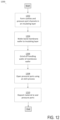
- FIG. 12 is a flowchart of a fabrication process for forming an ultrasonic transducer having a pressure port, according to some embodiments.
- the MUT may include a sealed cavity, for example sealed on a top and bottom side by a membrane and a substrate, respectively.
- the pressure port may represent an access hole to the sealed cavity.
- the pressure port may function to control the pressure within the sealed cavity during manufacture of the MUT. Once the pressure of the cavity, or cavities, is set as desired, the pressure port may be sealed.
- the inclusion of a pressure port for a MUT may provide various benefits.
- the pressure port may allow for control of the pressure of the sealed cavity of the MUT.
- Some ultrasound devices comprise large numbers of MUTs, such as hundreds, thousands, or hundreds of thousands of MUTs. Operation of such ultrasound devices may benefit in terms of accuracy and dynamic range (e.g., by minimizing damping) from having a substantially equal or uniform pressure across the area of the MUTs.
- providing pressure ports for individual MUTs or sub-groups of MUTs of the ultrasound device may facilitate achieving more uniform pressure across the sensing area.
- the pressure ports may allow for equalization of cavity pressure over a sensing area comprising multiple MUTs.
- the pressure ports may be used during manufacture, and sealed after the cavities are equalized in terms of pressure.
- each ultrasonic transducer may have one or more respective pressure ports.
- a pressure port may be shared by two or more ultrasonic transducers.
- an array of ultrasonic transducer may include respective pressure ports oriented at a same angle as each other relative to the array.
- an array of ultrasonic transducers may include respective pressure ports, in which two or more of the pressure ports are oriented at different angles relative to the array.
- the number of pressure ports provided for an array of ultrasonic transducers may be less than, equal to, or greater than the number of ultrasonic transducers. Further variations are possible.
- FIG. 1 is a non-limiting example, and is a perspective view of an array of micromachined ultrasonic transducers comprising pressure ports for access to cavities of the micromachined ultrasonic transducer.
- the ultrasound device 100 comprises an array of nine MUTs 102 , formed by a membrane 104 , insulating layer 106 , and cavities 108 .
- Pressure ports 110 are provided, and channels 112 interconnect the cavities 108 .
- insulating layer 106 may be a part of a complementary metal-oxide-semiconductor (CMOS) wafer, and cavities 108 can be formed in insulating layer 106 of the CMOS wafer.
- CMOS complementary metal-oxide-semiconductor
- the pressure ports 110 may have any suitable location. In the illustrated non-limiting example, they are positioned at the periphery of the array, and in this non-limiting example on two opposite side of the periphery of the array. When the pressure ports are disposed at the periphery of the array, as shown, control over the cavity pressure of the cavities internal to the array may still be achieved because of the presence of channels 112 , which may be air channels. However, alternative configurations are possible. For example, a pressure port may be provided for each individual cavity as shown in other embodiments. Alternatively, fewer pressure ports may be provided than shown, with additional channels 112 provided to allow for control of the cavity pressure across the array.
- the pressure ports 110 are positioned on two opposite sides of the array. In this non-limiting example, two pressure ports are positioned on a line bisecting the ultrasonic transducers in a given row. However, alternative positioning of pressure ports is possible.
- the pressure ports may have any suitable dimensions and may be formed in any suitable manner. In some embodiments, the pressure ports are sufficiently small to not have a negative impact on the performance of the ultrasonic transducers. Also, the pressure ports may be sufficiently small to allow them to be sealed once the pressures of cavities 108 are set to a desired value.
- the pressure ports may have diameters between approximately 0.1 microns and 20 microns, including any value or range of values within that range.
- the pressure ports may be sealed in any suitable manner, such as with a metal material. For example, aluminum may be sputtered to seal the pressure ports.
- the pressure ports may be created and used during manufacture of the MUT(s).
- the sealed cavities may be formed using a wafer bonding technique.
- the wafer bonding technique may be inadequate for achieving uniform cavity pressure across a wafer or array of MUTs.
- the chemicals present for wafer bonding may unequally occupy or remain in certain cavities of an array of MUTs.
- the pressure ports may be opened.
- the pressures of the sealed cavities may then be equalized, or made substantially equal, through exposure of the wafer to a desired, controlled pressure.
- desired chemicals e.g., Argon
- desired chemicals e.g., Argon
- control of the pressure and/or chemical content of the sealed cavities of a plurality of MUTs may be improved through use of a pressure port.
- the pressure port may provide greater control over these parameters than the wafer bonding process used for forming the sealed cavities.
- FIG. 2 illustrates a top view of the cavity layer of the ultrasound device 100 of FIG. 1 .
- nine cavities are included, interconnected by channels 112 .
- the channels 112 may be air channels, allowing pressure in the adjoining cavities to be set at a uniform level.
- the channels 112 may have any suitable dimensions for this purpose, such as being between 0.1 microns and 20 microns, including any value or range of values within that range.
- FIGS. 1 and 2 The ultrasound device of FIGS. 1 and 2 is a non-limiting example.
- the number of micromachined ultrasonic transducers shown, the shape, dimensions, and positioning are all variables.
- FIG. 2 illustrates circular cavities, but other shapes are possible, such as polygonal, square, or any other suitable shape.
- the positioning and number of pressure ports shown may also be selected for a particular application.
- FIG. 3 illustrates a perspective view of the cavity layer of the device of FIG. 1 including cavities and channels.
- the membrane layer of the ultrasound device 100 is omitted.
- the cavities 108 , channels 112 , and part of the pressure ports 110 may be formed, for example by etching.
- the membrane 104 may be formed to seal the cavities 108 by creating a membrane layer.
- a vertical part of the pressure ports 110 may then be etched through the membrane 104 to form the ultrasound device 100 .
- an array of ultrasonic transducers comprises an array of cavities with respective pressure ports.
- FIG. 4 illustrates an example, representing an alternative to FIG. 1 and having an array of ultrasonic transducers with respective pressure ports.
- the ultrasound device 400 includes the cavities 108 , membrane 104 , and insulating layer 106 .
- One pressure port is provided for each cavity 108 in this non-limiting embodiment.
- the cavities are not interconnected by channels 112 .
- the pressure ports are all oriented at a common angle relative to the cavities, and are not all disposed at a periphery of the cavity array.
- FIG. 5 is a schematic top view of the cavity layer of the structure of FIG. 4 .
- the cavities 108 include pressure ports 110 which include both a portion in-plane with the cavities and a portion perpendicular to the cavities (represented by the circles at the end of the portion in-plane with the cavities).
- FIG. 6 illustrates the cavity layer of FIG. 4 including cavities 108 and pressure ports 110 .
- the portion of the pressure ports in-plane with the cavities is illustrated.
- the portion of the pressure portions extending upward, perpendicular to the cavities 108 is not shown since that portion extends through the membrane 104 , which is not part of FIG. 6 .
- the cavities 108 and portions of the pressure ports 110 in-plane with the cavities 108 may be formed in any suitable manner.
- any suitable technique for etching the insulating layer 106 may be used to form the cavities 108 and in-plane portions of the pressure ports 110 .
- the ultrasound device 400 of FIG. 4 may be formed from the structure of FIG. 6 by forming the membrane 104 and etching vertical portions of the pressure ports 110 .
- FIGS. 1 and 4 illustrate two non-limiting examples.
- FIG. 7 illustrates a further alternative.
- two pressure ports are provided for each cavity. Providing more than one pressure port per cavity may make it easier to remove undesirable elements from the cavity, such as water or other elements. Having more than one port per cavity may also facilitate achieving a desired pressure for the cavity.
- the pressure ports are represented by the channels, or extensions, with the openings 702 at the end. It can be seen that the pressure ports 110 are oriented at an angle ⁇ with respect to the elevation direction. That angle may be between 5 degrees and 40 degrees, or any other suitable number. Also shown in FIG.
- Metal lines 704 and 706 are metal lines 704 and 706 .
- Metal lines 704 run in the azimuth direction, while metal lines 706 run in the elevation direction.
- the metal lines 704 and 706 may represent conductive traces for providing signals to/from the ultrasonic transducers.
- the metal of the metal lines may seal the ends of the pressure ports. For example, sputtering aluminum to form the metal lines may seal the pressure ports.
- FIG. 8 illustrates an alternative array of ultrasonic transducers and pressure ports comprising two pressure ports per ultrasonic transducer.
- the illustrated ultrasound device 800 differs from that of FIG. 7 in that the pressure ports for neighboring cavities are oriented differently than each other. In this example, when the pressure ports for a given cavity are oriented along the azimuth direction, the pressure ports for its immediately neighboring cavities are oriented along the elevation direction, and vice versa.
- FIG. 9 illustrates an alternative array of ultrasonic transducers and pressure ports in which the pressure ports are shared among the ultrasonic transducers.
- the ultrasound device 900 includes cavities 108 , metal lines 904 and 906 , channels 110 and access holes 902 .
- the pressure ports may represent a combination of channels 110 and access holes 902 .
- the access holes may extend vertically, for example perpendicular to the cavities 108 , as shown in FIG. 9 as openings 902 .
- the channels 110 may interconnect neighboring cavities 108 as shown. In this example, the same number of pressure ports and cavities are provided and the pressure ports are accessible internal to the array as opposed to being disposed at a periphery of the array.
- FIG. 10 is a cross-sectional view 10 of a pressure port of a type which may be used in the device of FIG. 9 .
- the pressure port includes a vertical portion represented by 902 , having a width X 1 , and an in-plane portion, or channel, with a width X 2 .
- the value of X 1 may be selected so as to be sufficiently small to not negatively impact operation of the ultrasonic transducer, and also to be sufficiently small to allow easy filling.
- X 1 may assume any of the value described previously herein with respect to pressure port and access hole dimensions, such as being between 0.1 microns and 20 microns.
- the value of X 2 may likewise assume any such value. In the illustrated example, X 1 is less than X 2 .
- membrane 104 may be formed of one or more layers with different material compositions.
- Membrane 104 may be formed from a silicon on insulator (SOI) wafer.
- the SOI wafer may comprise several layers, including but not limited to a buried oxide (BOX) layer 104 a , a single crystalline layer 104 b , and a thermal oxide layer 104 c .
- the SOI wafer may further comprise a handling wafer, which is removed after wafer bonding by any suitable technique such as chemical-mechanical polishing (CMP).
- BOX layer 104 a may be any suitable thickness, such as being between 0.5 and 2 microns thick or any other suitable value.
- Single crystalline layer 104 b may be single crystalline Si or any suitable single crystalline material.
- Single crystalline layer 104 b may also be any suitable thickness to enable operation of the MUTs, including being between 4 and 10 microns thick.
- Thermal oxide layer 104 c may be any suitable thickness, such as being between 100 and 300
- FIG. 11 is a cross-sectional view of a non-limiting example of a MUT 1100 having a cavity 108 and pressure port 110 .
- the pressure port may be sealed, and thus the illustrated device may represent the state of the device after the cavity pressure has been set to a desired value. At that point, the pressure port may be sealed with seal 1102 to provide a substantially constant pressure within the sealed cavity as a function of time.
- cavities 108 , pressure ports 110 , and/or channels 112 are formed in insulating layer 106 .
- Cavities 108 , pressure ports 110 , and/or channels 112 may be formed by any suitable etch process including reactive ion etching (RIE), deep reactive ion etching (DRIE), ion milling, plasma etching, or any other suitable method.
- Insulating layer 106 may be a part of a larger CMOS wafer such that the cavities are electrically coupled to other elements of the CMOS wafer.
- the insulating layer 106 with features may be wafer bonded to a membrane wafer, which may be an SOI wafer of the type discussed previously.
- the wafer bonding process may be a low temperature wafer bonding process.
- the wafer bonding process may also include a post-process annealing step. During annealing, gettering materials may be present to help control the pressure inside the cavities 108 .
- gettering materials might include Ti, TiN, SrO, and/or Zr—Al.
- the handling wafer of the membrane wafer may be ground off, allowing the membrane 104 above the cavities 108 to flex.
- the handling wafer may be ground off in any suitable way including chemical-mechanical polishing.
- openings such as openings 902 are formed to open pressure ports 110 , allowing the pressure of the cavities 108 to equalize. Openings may be formed using any suitable etch process such as RIE and/or DRIE. In some embodiments, RIE is first used to etch through BOX layer 104 a . Then, DRIE is used to etch single crystalline layer 104 b , and RIE is again used to etch through thermal oxide layer 104 c . Since the pressure ports 110 are opened under vacuum, any outgassed materials from the wafer bonding and/or annealing processes escape during act 1208 , and the pressure of the cavities 108 equalizes to that of the vacuum chamber.
- RIE is first used to etch through BOX layer 104 a . Then, DRIE is used to etch single crystalline layer 104 b , and RIE is again used to etch through thermal oxide layer 104 c . Since the pressure ports 110 are opened under vacuum, any outgassed materials from the wafer bonding and/or annealing
- the pressure ports 110 are sealed so that the cavities 108 may remain at a suitable pressure for operation.
- the pressure ports 110 may be sealed by any suitable material, or by any suitable process such as but not limited to a sputtering process.
- the pressure ports 110 may be sealed by a multilayered structure formed of multiple materials. Example materials include Al, Cu, Al/Cu alloys, and TiN in any suitable combination.
- the micromachined ultrasonic transducers described herein may be of various types. In some embodiments, they may be capacitive micromachined ultrasonic transducers (CMUTs). In such situations, they may be formed by wafer bonding or sacrificial release methods. In some embodiments, the micromachined ultrasonic transducers are piezoelectric micromachined ultrasonic transducers (PMUTs).
- CMUTs capacitive micromachined ultrasonic transducers
- PMUTs piezoelectric micromachined ultrasonic transducers
- a handheld ultrasound probe may include an ultrasound-on-a-chip comprising MUTs with pressure ports.
- an ultrasound patch may implement the technology.
- a pill may also utilize the technology.
- some aspects may be embodied as one or more methods.
- the acts performed as part of the method(s) may be ordered in any suitable way. Accordingly, embodiments may be constructed in which acts are performed in an order different than illustrated, which may include performing some acts simultaneously, even though shown as sequential acts in illustrative embodiments.
- the phrase “at least one,” in reference to a list of one or more elements, should be understood to mean at least one element selected from any one or more of the elements in the list of elements, but not necessarily including at least one of each and every element specifically listed within the list of elements and not excluding any combinations of elements in the list of elements.
- the term “between” used in a numerical context is to be inclusive unless indicated otherwise.
- “between A and B” includes A and B unless indicated otherwise.
- the terms “approximately” and “about” may be used to mean within ⁇ 20% of a target value in some embodiments, within ⁇ 10% of a target value in some embodiments, within ⁇ 5% of a target value in some embodiments, and yet within ⁇ 2% of a target value in some embodiments.
- the terms “approximately” and “about” may include the target value.
Landscapes
- Health & Medical Sciences (AREA)
- Life Sciences & Earth Sciences (AREA)
- Engineering & Computer Science (AREA)
- Mechanical Engineering (AREA)
- General Health & Medical Sciences (AREA)
- Physics & Mathematics (AREA)
- Pathology (AREA)
- Molecular Biology (AREA)
- Heart & Thoracic Surgery (AREA)
- Veterinary Medicine (AREA)
- Public Health (AREA)
- Animal Behavior & Ethology (AREA)
- Biophysics (AREA)
- Nuclear Medicine, Radiotherapy & Molecular Imaging (AREA)
- Radiology & Medical Imaging (AREA)
- Biomedical Technology (AREA)
- Surgery (AREA)
- Medical Informatics (AREA)
- Chemical & Material Sciences (AREA)
- Biochemistry (AREA)
- Analytical Chemistry (AREA)
- Immunology (AREA)
- General Physics & Mathematics (AREA)
- Gynecology & Obstetrics (AREA)
- Micromachines (AREA)
- Transducers For Ultrasonic Waves (AREA)
Abstract
Description
Claims (16)
Priority Applications (2)
| Application Number | Priority Date | Filing Date | Title |
|---|---|---|---|
| US16/401,870 US12053323B2 (en) | 2018-05-03 | 2019-05-02 | Pressure port for ultrasonic transducer on CMOS sensor |
| US18/793,062 US20250090138A1 (en) | 2018-05-03 | 2024-08-02 | Pressure port for ultrasonic transducer on cmos sensor |
Applications Claiming Priority (3)
| Application Number | Priority Date | Filing Date | Title |
|---|---|---|---|
| US201862666556P | 2018-05-03 | 2018-05-03 | |
| US201862696305P | 2018-07-10 | 2018-07-10 | |
| US16/401,870 US12053323B2 (en) | 2018-05-03 | 2019-05-02 | Pressure port for ultrasonic transducer on CMOS sensor |
Related Child Applications (1)
| Application Number | Title | Priority Date | Filing Date |
|---|---|---|---|
| US18/793,062 Continuation US20250090138A1 (en) | 2018-05-03 | 2024-08-02 | Pressure port for ultrasonic transducer on cmos sensor |
Publications (2)
| Publication Number | Publication Date |
|---|---|
| US20190336099A1 US20190336099A1 (en) | 2019-11-07 |
| US12053323B2 true US12053323B2 (en) | 2024-08-06 |
Family
ID=68384340
Family Applications (2)
| Application Number | Title | Priority Date | Filing Date |
|---|---|---|---|
| US16/401,870 Active 2040-05-19 US12053323B2 (en) | 2018-05-03 | 2019-05-02 | Pressure port for ultrasonic transducer on CMOS sensor |
| US18/793,062 Pending US20250090138A1 (en) | 2018-05-03 | 2024-08-02 | Pressure port for ultrasonic transducer on cmos sensor |
Family Applications After (1)
| Application Number | Title | Priority Date | Filing Date |
|---|---|---|---|
| US18/793,062 Pending US20250090138A1 (en) | 2018-05-03 | 2024-08-02 | Pressure port for ultrasonic transducer on cmos sensor |
Country Status (9)
| Country | Link |
|---|---|
| US (2) | US12053323B2 (en) |
| EP (1) | EP3788798B1 (en) |
| JP (1) | JP2021522734A (en) |
| KR (1) | KR20210005208A (en) |
| CN (1) | CN112075090B (en) |
| AU (1) | AU2019263404A1 (en) |
| CA (1) | CA3098911A1 (en) |
| TW (1) | TW202000137A (en) |
| WO (1) | WO2019213388A1 (en) |
Families Citing this family (18)
| Publication number | Priority date | Publication date | Assignee | Title |
|---|---|---|---|---|
| WO2016106153A1 (en) * | 2014-12-21 | 2016-06-30 | Chirp Microsystems, Inc. | Piezoelectric micromachined ultrasonic transducers with low stress sensitivity and methods of fabrication |
| JP7385652B2 (en) | 2018-09-28 | 2023-11-22 | バタフライ ネットワーク,インコーポレイテッド | Manufacturing technology and structure of gettering material in ultrasonic transducer cavity |
| CN113039024A (en) | 2018-11-13 | 2021-06-25 | 蝴蝶网络有限公司 | Getter technology for micromechanical ultrasound transducer cavities |
| CA3119753A1 (en) | 2018-11-15 | 2020-05-22 | Butterfly Network, Inc. | Anti-stiction bottom cavity surface for micromachined ultrasonic transducer devices |
| TW202045099A (en) | 2019-02-07 | 2020-12-16 | 美商蝴蝶網路公司 | Bi-layer metal electrode for micromachined ultrasonic transducer devices |
| TW202102312A (en) | 2019-02-25 | 2021-01-16 | 美商蝴蝶網路公司 | Adaptive cavity thickness control for micromachined ultrasonic transducer devices |
| US12515240B2 (en) | 2019-04-12 | 2026-01-06 | Bfly Operations, Inc. | Segmented getter openings for micromachined ultrasound transducer devices |
| US11484911B2 (en) | 2019-04-12 | 2022-11-01 | Bfly Operations, Inc. | Bottom electrode via structures for micromachined ultrasonic transducer devices |
| US11501562B2 (en) | 2019-04-30 | 2022-11-15 | Bfly Operations, Inc. | Ultrasound face scanning and identification apparatuses and methods |
| FR3097091B1 (en) * | 2019-06-07 | 2021-07-23 | Commissariat Energie Atomique | device provided with a plurality of resonators collectively exhibiting an improved quality factor |
| US11684951B2 (en) | 2019-08-08 | 2023-06-27 | Bfly Operations, Inc. | Micromachined ultrasonic transducer devices having truncated circle shaped cavities |
| US11988640B2 (en) | 2020-03-11 | 2024-05-21 | Bfly Operations, Inc. | Bottom electrode material stack for micromachined ultrasonic transducer devices |
| TWI742603B (en) * | 2020-04-09 | 2021-10-11 | 伊諾司生技股份有限公司 | A sensor with a chamber |
| US11815492B2 (en) | 2020-04-16 | 2023-11-14 | Bfly Operations, Inc. | Methods and circuitry for built-in self-testing of circuitry and/or transducers in ultrasound devices |
| US20210403321A1 (en) * | 2020-06-30 | 2021-12-30 | Butterfly Network, Inc. | Formation of self-assembled monolayer for ultrasonic transducers |
| KR20230104684A (en) | 2020-11-19 | 2023-07-10 | 카톨리에케 유니버시테이트 루벤 | Ultrasonic Transducer Array Device |
| WO2022187467A2 (en) | 2021-03-04 | 2022-09-09 | Butterfly Network, Inc. | Micromachined ultrasound transducer with pedestal |
| WO2022187482A1 (en) | 2021-03-04 | 2022-09-09 | Butterfly Network, Inc. | Capacitive micromachined ultrasonic transducers (cmuts) having non-uniform pedestals |
Citations (112)
| Publication number | Priority date | Publication date | Assignee | Title |
|---|---|---|---|---|
| US4262399A (en) * | 1978-11-08 | 1981-04-21 | General Electric Co. | Ultrasonic transducer fabricated as an integral park of a monolithic integrated circuit |
| JPH01296122A (en) | 1988-05-24 | 1989-11-29 | Matsushita Electric Ind Co Ltd | pressure sensor |
| EP0389071A2 (en) * | 1989-01-30 | 1990-09-26 | Dresser Industries Inc. | Method for fabricating semiconductor diaphragms |
| US5311095A (en) * | 1992-05-14 | 1994-05-10 | Duke University | Ultrasonic transducer array |
| US5619476A (en) * | 1994-10-21 | 1997-04-08 | The Board Of Trustees Of The Leland Stanford Jr. Univ. | Electrostatic ultrasonic transducer |
| US5639423A (en) * | 1992-08-31 | 1997-06-17 | The Regents Of The University Of Calfornia | Microfabricated reactor |
| US5744898A (en) * | 1992-05-14 | 1998-04-28 | Duke University | Ultrasound transducer array with transmitter/receiver integrated circuitry |
| US5894452A (en) * | 1994-10-21 | 1999-04-13 | The Board Of Trustees Of The Leland Stanford Junior University | Microfabricated ultrasonic immersion transducer |
| US5982709A (en) * | 1998-03-31 | 1999-11-09 | The Board Of Trustees Of The Leland Stanford Junior University | Acoustic transducers and method of microfabrication |
| US6262946B1 (en) * | 1999-09-29 | 2001-07-17 | The Board Of Trustees Of The Leland Stanford Junior University | Capacitive micromachined ultrasonic transducer arrays with reduced cross-coupling |
| US6271620B1 (en) * | 1999-05-20 | 2001-08-07 | Sen Corporation | Acoustic transducer and method of making the same |
| US6278224B1 (en) * | 1998-07-31 | 2001-08-21 | Olympus Optical Co., Ltd. | Ultrasonic transducer and method for manufacturing the same |
| US6323580B1 (en) * | 1999-04-28 | 2001-11-27 | The Charles Stark Draper Laboratory, Inc. | Ferroic transducer |
| US6328697B1 (en) * | 2000-06-15 | 2001-12-11 | Atl Ultrasound, Inc. | Capacitive micromachined ultrasonic transducers with improved capacitive response |
| US20020083771A1 (en) * | 2000-07-14 | 2002-07-04 | Khuri-Yakub Butrus T. | Fluidic device with integrated capacitive micromachined ultrasonic transducers |
| US6430109B1 (en) * | 1999-09-30 | 2002-08-06 | The Board Of Trustees Of The Leland Stanford Junior University | Array of capacitive micromachined ultrasonic transducer elements with through wafer via connections |
| US6891711B1 (en) * | 2004-04-08 | 2005-05-10 | Kulite Semiconductor Products, Inc. | Ultra-miniature, high temperature, capacitive inductive pressure transducer |
| WO2005114820A2 (en) * | 2004-05-14 | 2005-12-01 | The University Of Georgia Research Foundation, Inc. | Implantable ultrasonic transducer systems and methods |
| US20060163680A1 (en) * | 2004-12-30 | 2006-07-27 | Jingkuang Chen | Micro-machined medical devices, methods of fabricating microdevices, and methods of medical diagnosis, imaging, stimulation, and treatment |
| EP1761104A1 (en) * | 2004-06-03 | 2007-03-07 | Olympus Corporation | Electrostatic capacity type ultrasonic vibrator, manufacturing method thereof, and electrostatic capacity type ultrasonic probe |
| GB2436460A (en) * | 2006-03-20 | 2007-09-26 | Wolfson Microelectronics Plc | MEMS capacitive microphone |
| US20080089181A1 (en) | 2006-10-12 | 2008-04-17 | Olympus Medical Systems Corp. | Ultrasonic transducer cell |
| US7616077B1 (en) * | 2007-03-22 | 2009-11-10 | Sandia Corporation | Microelectromechanical resonator and method for fabrication |
| US20100168583A1 (en) * | 2006-11-03 | 2010-07-01 | Research Triangle Institute | Enhanced ultrasound imaging probes using flexure mode piezoelectric transducers |
| US20100207484A1 (en) * | 2007-09-25 | 2010-08-19 | Canon Kabushiki Kaisha | Electromechanical transducer and manufacturing method therefor |
| WO2010100861A1 (en) * | 2009-03-05 | 2010-09-10 | 株式会社日立メディコ | Ultrasonic transducer, method of producing same, and ultrasound probe using same |
| WO2010109205A2 (en) * | 2009-03-26 | 2010-09-30 | Ntnu Technology Transfer As | Cmut array |
| US20100327695A1 (en) * | 2009-06-30 | 2010-12-30 | Avago Technologies Wireless Ip (Singapore) Pte. Ltd. | Multi-frequency acoustic array |
| US20110036808A1 (en) * | 2006-10-11 | 2011-02-17 | Olympus Medical Systems Corp. | Ultrasonic transducer, ultrasonic transducer fabrication method, and ultrasonic endoscope |
| US20110055447A1 (en) | 2008-05-07 | 2011-03-03 | Signostics Limited | Docking system for medical diagnostic scanning using a handheld device |
| US20110073968A1 (en) * | 2008-06-30 | 2011-03-31 | Canon Kabushiki Kaisha | Element array, electromechanical conversion device, and process for producing the same |
| US20110095645A1 (en) * | 2007-09-25 | 2011-04-28 | Canon Kabushiki Kaisha | Electromechanical transducer and manufacturing method therefor |
| US20110115337A1 (en) * | 2009-11-16 | 2011-05-19 | Seiko Epson Corporation | Ultrasonic transducer, ultrasonic sensor, method of manufacturing ultrasonic transducer, and method of manufacturing ultrasonic sensor |
| US20110120971A1 (en) * | 2009-11-23 | 2011-05-26 | Avago Technologies Wireless Ip (Singapore) Pte. Ltd. | Micromachined transducers and method of fabrication |
| US20110260576A1 (en) * | 2010-04-23 | 2011-10-27 | Canon Kabushiki Kaisha | Electromechanical transducer and method for fabricating the same |
| US20110316054A1 (en) | 2010-06-04 | 2011-12-29 | Carnegie Mellon University | Method, Apparatus, and System for Micromechanical Gas Chemical Sensing Capacitor |
| US20120086087A1 (en) | 2010-10-12 | 2012-04-12 | Fitzpatrick Glen A | Soi-based cmut device with buried electrodes |
| US20120112603A1 (en) * | 2010-11-04 | 2012-05-10 | Canon Kabushiki Kaisha | Electromechanical transducer and method of fabricating the same |
| EP2508269A2 (en) * | 2011-04-06 | 2012-10-10 | Canon Kabushiki Kaisha | Electromechanical transducer and method of producing the same |
| US20120256520A1 (en) * | 2011-04-06 | 2012-10-11 | Canon Kabushiki Kaisha | Electromechanical transducer and method of producing the same |
| US20120256519A1 (en) * | 2011-04-06 | 2012-10-11 | Canon Kabushiki Kaisha | Electromechanical transducer and method of producing the same |
| US8324006B1 (en) * | 2009-10-28 | 2012-12-04 | National Semiconductor Corporation | Method of forming a capacitive micromachined ultrasonic transducer (CMUT) |
| WO2014080310A2 (en) * | 2012-11-20 | 2014-05-30 | Koninklijke Philips N.V. | Capacitive micro-machined transducer and method of manufacturing the same |
| EP2792423A2 (en) * | 2013-04-18 | 2014-10-22 | Canon Kabushiki Kaisha | Transducer, method for manufacturing transducer, and object information acquiring apparatus |
| US20140332911A1 (en) * | 2012-01-27 | 2014-11-13 | Koninklijke Philips N.V. | Capacitive micro-machined transducer and method of manufacturing the same |
| US20140375168A1 (en) * | 2012-01-27 | 2014-12-25 | Koninklijke Philips N.V. | Capacitive micro-machined transducer and method of manufacturing the same |
| US20150107360A1 (en) * | 2013-10-22 | 2015-04-23 | Canon Kabushiki Kaisha | Capacitance type transducer and method of manufacturing the same |
| US20150135841A1 (en) * | 2013-11-19 | 2015-05-21 | Canon Kabushiki Kaisha | Capacitive transducer and method of manufacturing the same |
| JP2015103821A (en) * | 2013-11-20 | 2015-06-04 | キヤノン株式会社 | Capacitance type transducer and manufacturing method thereof |
| US20150165479A1 (en) * | 2013-12-12 | 2015-06-18 | Qualcomm Incorporated | Piezoelectric ultrasonic transducer and process |
| US9061318B2 (en) | 2013-03-15 | 2015-06-23 | Butterfly Network, Inc. | Complementary metal oxide semiconductor (CMOS) ultrasonic transducers and methods for forming the same |
| US9067779B1 (en) | 2014-07-14 | 2015-06-30 | Butterfly Network, Inc. | Microfabricated ultrasonic transducers and related apparatus and methods |
| WO2016007250A1 (en) | 2014-07-08 | 2016-01-14 | Qualcomm Incorporated | Piezoelectric ultrasonic transducer and process |
| US20160023244A1 (en) | 2014-07-28 | 2016-01-28 | Kolo Medical Ltd. | High displacement ultrasonic transducer |
| US20160107194A1 (en) | 2014-10-15 | 2016-04-21 | Qualcomm Incorporated | Three-port piezoelectric ultrasonic transducer |
| US9351706B2 (en) | 2013-07-23 | 2016-05-31 | Butterfly Network, Inc. | Interconnectable ultrasound transducer probes and related methods and apparatus |
| US20160153939A1 (en) * | 2014-11-28 | 2016-06-02 | Canon Kabushiki Kaisha | Capacitive micromachined ultrasonic transducer and test object information acquiring apparatus including capacitive micromachined ultrasonic transducer |
| WO2016106153A1 (en) | 2014-12-21 | 2016-06-30 | Chirp Microsystems, Inc. | Piezoelectric micromachined ultrasonic transducers with low stress sensitivity and methods of fabrication |
| US20160219375A1 (en) * | 2015-01-23 | 2016-07-28 | Silicon Audio Directional, Llc | Multi-mode Microphones |
| US9420378B1 (en) * | 2010-07-12 | 2016-08-16 | Amkor Technology, Inc. | Top port MEMS microphone package and method |
| US9439000B1 (en) * | 2014-02-28 | 2016-09-06 | Google Inc. | Systems and methods for improved audio output in electronic devices |
| US9499392B2 (en) | 2013-02-05 | 2016-11-22 | Butterfly Network, Inc. | CMOS ultrasonic transducers and related apparatus and methods |
| US9505030B2 (en) | 2014-04-18 | 2016-11-29 | Butterfly Network, Inc. | Ultrasonic transducers in complementary metal oxide semiconductor (CMOS) wafers and related apparatus and methods |
| US9521991B2 (en) | 2013-03-15 | 2016-12-20 | Butterfly Network, Inc. | Monolithic ultrasonic imaging devices, systems and methods |
| US20170069820A1 (en) * | 2014-06-13 | 2017-03-09 | Murata Manufacturing Co., Ltd. | Piezoelectric device and method of manufacturing piezoelectric device |
| US20170110504A1 (en) * | 2015-10-14 | 2017-04-20 | Qualcomm Incorporated | Integrated piezoelectric micromechanical ultrasonic transducer pixel and array |
| US20170170383A1 (en) * | 2014-01-24 | 2017-06-15 | The Regents Of The University Of California | Curved Piezoelectric Transducers and Methods of Making and Using the Same |
| US20170258448A1 (en) * | 2016-03-08 | 2017-09-14 | Canon Kabushiki Kaisha | Ultrasonic transducer unit, and information acquisition apparatus including the ultrasonic transducer unit |
| US9778348B1 (en) | 2016-03-31 | 2017-10-03 | Butterfly Network, Inc. | Symmetric receiver switch for bipolar pulser |
| US20170365774A1 (en) | 2016-06-20 | 2017-12-21 | Jonathan M. Rothberg | Electrical contact arrangement for microfabricated ultrasonic transducer |
| US20180221917A1 (en) * | 2017-02-09 | 2018-08-09 | Canon Kabushiki Kaisha | Capacitive micromachined ultrasonic transducer and method for manufacturing the same |
| US20180257927A1 (en) | 2017-03-08 | 2018-09-13 | Butterfly Network, Inc. | Microfabricated ultrasonic transducers and related apparatus and methods |
| US10082565B2 (en) | 2016-03-31 | 2018-09-25 | Butterfly Network, Inc. | Multilevel bipolar pulser |
| US20180312399A1 (en) * | 2015-10-14 | 2018-11-01 | Agency For Science, Technology And Research | Device arrangement |
| US20180369862A1 (en) | 2017-06-21 | 2018-12-27 | Butterfly Network, Inc. | Microfabricated ultrasonic transducer having individual cells with electrically isolated electrode sections |
| US10175347B2 (en) | 2015-12-02 | 2019-01-08 | Butterfly Network, Inc. | Ultrasound receiver circuitry and related apparatus and methods |
| US10187020B2 (en) | 2015-12-02 | 2019-01-22 | Butterfly Network, Inc. | Trans-impedance amplifier for ultrasound device and related apparatus and methods |
| US10189049B2 (en) * | 2013-04-25 | 2019-01-29 | Canon Kabushiki Kaisha | Capacitive transducer and method of manufacturing same |
| US20190069842A1 (en) | 2017-09-07 | 2019-03-07 | Butterfly Network, Inc. | Wrist bound ultrasound-on-a-chip device |
| US10231713B2 (en) | 2016-09-13 | 2019-03-19 | Butterfly Network, Inc. | Analog-to-digital drive circuitry having built-in time gain compensation functionality for ultrasound applications |
| US20190142387A1 (en) | 2017-11-15 | 2019-05-16 | Butterfly Network, Inc. | Ultrasound apparatuses and methods for fabricating ultrasound devices |
| US10293374B2 (en) * | 2013-04-25 | 2019-05-21 | Canon Kabushiki Kaisha | Capacitive transducer and method of manufacturing same |
| US20190193116A1 (en) * | 2016-06-17 | 2019-06-27 | Chirp Microsystems, Inc. | Piezoelectric micromachined ultrasonic transducers having stress relief features |
| US20190231312A1 (en) | 2018-01-30 | 2019-08-01 | Butterfly Network, Inc. | Methods and apparatuses for packaging an ultrasound-on-a-chip |
| US20190275561A1 (en) | 2018-03-09 | 2019-09-12 | Butterfly Network, Inc. | Ultrasound transducer devices and methods for fabricating ultrasound transducer devices |
| US20190299251A1 (en) | 2017-11-15 | 2019-10-03 | Butterfly Network, Inc. | Apparatuses including a capacitive micromachined ultrasonic transducer directly coupled to an analog-to-digital converter |
| US20190336104A1 (en) | 2018-05-03 | 2019-11-07 | Butterfly Network, Inc. | Ultrasound devices |
| US20200041459A1 (en) * | 2018-07-31 | 2020-02-06 | Canon Kabushiki Kaisha | Capacitive transducer and ultrasonic probe using same |
| US20200102214A1 (en) | 2018-09-28 | 2020-04-02 | Butterfly Network, Inc. | Fabrication techniques and structures for gettering materials in ultrasonic transducer cavities |
| US20200123005A1 (en) * | 2017-06-30 | 2020-04-23 | Canon Kabushiki Kaisha | Method for producing hollow structure and hollow structure |
| US20200147641A1 (en) | 2018-11-13 | 2020-05-14 | Butterfly Network, Inc. | Getter technology for micromachined ultrasonic transducer cavities |
| US20200150252A1 (en) | 2018-11-09 | 2020-05-14 | Butterfly Network, Inc. | Trans-impedance amplifier (tia) for ultrasound devices |
| US20200156110A1 (en) | 2018-11-15 | 2020-05-21 | Butterfly Network, Inc. | Anti-stiction bottom cavity surface for micromachined ultrasonic transducer devices |
| US20200184177A1 (en) | 2018-12-07 | 2020-06-11 | Butterfly Network, Inc. | Ultrasound fingerprint detection and related apparatus and methods |
| US20200184176A1 (en) | 2018-12-07 | 2020-06-11 | Butterfly Network, Inc. | Ultrasound fingerprint detection and related apparatus and methods |
| US20200239299A1 (en) | 2019-01-29 | 2020-07-30 | Butterfly Network, Inc. | Packaging structures and packaging methods for ultrasound-on-chip devices |
| US20200254487A1 (en) | 2019-02-07 | 2020-08-13 | Butterfly Network, Inc. | Bi-layer metal electrode for micromachined ultrasonic transducer devices |
| US20200269279A1 (en) | 2019-02-25 | 2020-08-27 | Butterfly Network, Inc. | Adaptive cavity thickness control for micromachined ultrasonic transducer devices |
| US20200269280A1 (en) | 2017-11-15 | 2020-08-27 | Butterfly Network, Inc. | Ultrasound device with piezoelectric micromachined ultrasonic transducers |
| US20200324318A1 (en) | 2019-04-12 | 2020-10-15 | Butterfly Network, Inc. | Segmented getter openings for micromachined ultrasound transducer devices |
| US20200324319A1 (en) | 2019-04-12 | 2020-10-15 | Butterfly Network, Inc. | Bottom electrode via structures for micromachined ultrasonic transducer devices |
| US20200348794A1 (en) | 2019-04-30 | 2020-11-05 | Butterfly Network, Inc. | Ultrasound touch detection and related apparatuses and methods |
| US20200349342A1 (en) | 2019-04-30 | 2020-11-05 | Butterfly Network, Inc. | Ultrasound face scanning and identification apparatuses and methods |
| US10850306B2 (en) | 2017-02-27 | 2020-12-01 | Butterfly Network, Inc. | Capacitive micromachined ultrasonic transducers (CMUTs) and related apparatus and methods |
| US10856840B2 (en) | 2016-06-20 | 2020-12-08 | Butterfly Network, Inc. | Universal ultrasound device and related apparatus and methods |
| US10856844B2 (en) | 2018-05-03 | 2020-12-08 | Butterfly Network, Inc. | Vertical packaging for ultrasound-on-a-chip and related methods |
| US20210028792A1 (en) | 2019-07-25 | 2021-01-28 | Butterfly Network, Inc. | Methods and apparatuses for turning on and off an adc driver in an ultrasound device |
| US20210038193A1 (en) | 2019-08-08 | 2021-02-11 | Butterfly Network, Inc. | Micromachined ultrasonic transducer devices having truncated circle shaped cavities |
| US20210088638A1 (en) | 2019-09-19 | 2021-03-25 | Butterfly Network, Inc. | Symmetric receiver switch for ultrasound devices |
| US10972842B2 (en) | 2017-06-23 | 2021-04-06 | Butterfly Network, Inc. | Differential ultrasonic transducer element for ultrasound devices |
| US11018068B2 (en) | 2018-07-06 | 2021-05-25 | Butterfly Network, Inc. | Methods and apparatuses for packaging an ultrasound-on-a-chip |
| US20210183832A1 (en) | 2019-12-17 | 2021-06-17 | Butterfly Network, Inc. | Methods and apparatuses for packaging ultrasound-on-chip devices |
Family Cites Families (1)
| Publication number | Priority date | Publication date | Assignee | Title |
|---|---|---|---|---|
| JP5529577B2 (en) * | 2010-02-14 | 2014-06-25 | キヤノン株式会社 | Electromechanical transducer and method for manufacturing the same |
-
2019
- 2019-05-02 KR KR1020207034403A patent/KR20210005208A/en not_active Ceased
- 2019-05-02 US US16/401,870 patent/US12053323B2/en active Active
- 2019-05-02 JP JP2020560488A patent/JP2021522734A/en active Pending
- 2019-05-02 EP EP19795861.4A patent/EP3788798B1/en active Active
- 2019-05-02 TW TW108115250A patent/TW202000137A/en unknown
- 2019-05-02 CA CA3098911A patent/CA3098911A1/en active Pending
- 2019-05-02 AU AU2019263404A patent/AU2019263404A1/en not_active Abandoned
- 2019-05-02 CN CN201980029781.8A patent/CN112075090B/en active Active
- 2019-05-02 WO PCT/US2019/030388 patent/WO2019213388A1/en not_active Ceased
-
2024
- 2024-08-02 US US18/793,062 patent/US20250090138A1/en active Pending
Patent Citations (132)
| Publication number | Priority date | Publication date | Assignee | Title |
|---|---|---|---|---|
| US4262399A (en) * | 1978-11-08 | 1981-04-21 | General Electric Co. | Ultrasonic transducer fabricated as an integral park of a monolithic integrated circuit |
| JPH01296122A (en) | 1988-05-24 | 1989-11-29 | Matsushita Electric Ind Co Ltd | pressure sensor |
| EP0389071A2 (en) * | 1989-01-30 | 1990-09-26 | Dresser Industries Inc. | Method for fabricating semiconductor diaphragms |
| US5744898A (en) * | 1992-05-14 | 1998-04-28 | Duke University | Ultrasound transducer array with transmitter/receiver integrated circuitry |
| US5311095A (en) * | 1992-05-14 | 1994-05-10 | Duke University | Ultrasonic transducer array |
| US5639423A (en) * | 1992-08-31 | 1997-06-17 | The Regents Of The University Of Calfornia | Microfabricated reactor |
| US5894452A (en) * | 1994-10-21 | 1999-04-13 | The Board Of Trustees Of The Leland Stanford Junior University | Microfabricated ultrasonic immersion transducer |
| US5870351A (en) * | 1994-10-21 | 1999-02-09 | The Board Of Trustees Of The Leland Stanford Junior University | Broadband microfabriated ultrasonic transducer and method of fabrication |
| US5619476A (en) * | 1994-10-21 | 1997-04-08 | The Board Of Trustees Of The Leland Stanford Jr. Univ. | Electrostatic ultrasonic transducer |
| US5982709A (en) * | 1998-03-31 | 1999-11-09 | The Board Of Trustees Of The Leland Stanford Junior University | Acoustic transducers and method of microfabrication |
| US6278224B1 (en) * | 1998-07-31 | 2001-08-21 | Olympus Optical Co., Ltd. | Ultrasonic transducer and method for manufacturing the same |
| US6323580B1 (en) * | 1999-04-28 | 2001-11-27 | The Charles Stark Draper Laboratory, Inc. | Ferroic transducer |
| US6271620B1 (en) * | 1999-05-20 | 2001-08-07 | Sen Corporation | Acoustic transducer and method of making the same |
| US6262946B1 (en) * | 1999-09-29 | 2001-07-17 | The Board Of Trustees Of The Leland Stanford Junior University | Capacitive micromachined ultrasonic transducer arrays with reduced cross-coupling |
| US6430109B1 (en) * | 1999-09-30 | 2002-08-06 | The Board Of Trustees Of The Leland Stanford Junior University | Array of capacitive micromachined ultrasonic transducer elements with through wafer via connections |
| US6328697B1 (en) * | 2000-06-15 | 2001-12-11 | Atl Ultrasound, Inc. | Capacitive micromachined ultrasonic transducers with improved capacitive response |
| US20020083771A1 (en) * | 2000-07-14 | 2002-07-04 | Khuri-Yakub Butrus T. | Fluidic device with integrated capacitive micromachined ultrasonic transducers |
| US6891711B1 (en) * | 2004-04-08 | 2005-05-10 | Kulite Semiconductor Products, Inc. | Ultra-miniature, high temperature, capacitive inductive pressure transducer |
| WO2005114820A2 (en) * | 2004-05-14 | 2005-12-01 | The University Of Georgia Research Foundation, Inc. | Implantable ultrasonic transducer systems and methods |
| EP1761104A1 (en) * | 2004-06-03 | 2007-03-07 | Olympus Corporation | Electrostatic capacity type ultrasonic vibrator, manufacturing method thereof, and electrostatic capacity type ultrasonic probe |
| US20060163680A1 (en) * | 2004-12-30 | 2006-07-27 | Jingkuang Chen | Micro-machined medical devices, methods of fabricating microdevices, and methods of medical diagnosis, imaging, stimulation, and treatment |
| GB2436460A (en) * | 2006-03-20 | 2007-09-26 | Wolfson Microelectronics Plc | MEMS capacitive microphone |
| US20110036808A1 (en) * | 2006-10-11 | 2011-02-17 | Olympus Medical Systems Corp. | Ultrasonic transducer, ultrasonic transducer fabrication method, and ultrasonic endoscope |
| US20080089181A1 (en) | 2006-10-12 | 2008-04-17 | Olympus Medical Systems Corp. | Ultrasonic transducer cell |
| US7940603B2 (en) | 2006-10-12 | 2011-05-10 | Olympus Medical Systems Corporation | Ultrasonic transducer cell |
| US20100168583A1 (en) * | 2006-11-03 | 2010-07-01 | Research Triangle Institute | Enhanced ultrasound imaging probes using flexure mode piezoelectric transducers |
| US7616077B1 (en) * | 2007-03-22 | 2009-11-10 | Sandia Corporation | Microelectromechanical resonator and method for fabrication |
| US20100207484A1 (en) * | 2007-09-25 | 2010-08-19 | Canon Kabushiki Kaisha | Electromechanical transducer and manufacturing method therefor |
| US20110095645A1 (en) * | 2007-09-25 | 2011-04-28 | Canon Kabushiki Kaisha | Electromechanical transducer and manufacturing method therefor |
| US20110055447A1 (en) | 2008-05-07 | 2011-03-03 | Signostics Limited | Docking system for medical diagnostic scanning using a handheld device |
| US20110073968A1 (en) * | 2008-06-30 | 2011-03-31 | Canon Kabushiki Kaisha | Element array, electromechanical conversion device, and process for producing the same |
| US20110316383A1 (en) * | 2009-03-05 | 2011-12-29 | Hitachi Medical Corporation | Ultrasonic transducer, method of producing same, and ultrasonic probe using same |
| WO2010100861A1 (en) * | 2009-03-05 | 2010-09-10 | 株式会社日立メディコ | Ultrasonic transducer, method of producing same, and ultrasound probe using same |
| WO2010109205A2 (en) * | 2009-03-26 | 2010-09-30 | Ntnu Technology Transfer As | Cmut array |
| US20100327695A1 (en) * | 2009-06-30 | 2010-12-30 | Avago Technologies Wireless Ip (Singapore) Pte. Ltd. | Multi-frequency acoustic array |
| US8324006B1 (en) * | 2009-10-28 | 2012-12-04 | National Semiconductor Corporation | Method of forming a capacitive micromachined ultrasonic transducer (CMUT) |
| US20110115337A1 (en) * | 2009-11-16 | 2011-05-19 | Seiko Epson Corporation | Ultrasonic transducer, ultrasonic sensor, method of manufacturing ultrasonic transducer, and method of manufacturing ultrasonic sensor |
| US20110120971A1 (en) * | 2009-11-23 | 2011-05-26 | Avago Technologies Wireless Ip (Singapore) Pte. Ltd. | Micromachined transducers and method of fabrication |
| US20110260576A1 (en) * | 2010-04-23 | 2011-10-27 | Canon Kabushiki Kaisha | Electromechanical transducer and method for fabricating the same |
| US20110316054A1 (en) | 2010-06-04 | 2011-12-29 | Carnegie Mellon University | Method, Apparatus, and System for Micromechanical Gas Chemical Sensing Capacitor |
| US9420378B1 (en) * | 2010-07-12 | 2016-08-16 | Amkor Technology, Inc. | Top port MEMS microphone package and method |
| US20120086087A1 (en) | 2010-10-12 | 2012-04-12 | Fitzpatrick Glen A | Soi-based cmut device with buried electrodes |
| US20120112603A1 (en) * | 2010-11-04 | 2012-05-10 | Canon Kabushiki Kaisha | Electromechanical transducer and method of fabricating the same |
| US20170333945A1 (en) * | 2011-04-06 | 2017-11-23 | Canon Kabushiki Kaisha | Electromechanical transducer and method of producing the same |
| US20120256519A1 (en) * | 2011-04-06 | 2012-10-11 | Canon Kabushiki Kaisha | Electromechanical transducer and method of producing the same |
| US20120256518A1 (en) * | 2011-04-06 | 2012-10-11 | Canon Kabushiki Kaisha | Electromechanical transducer and method of producing the same |
| US20120256520A1 (en) * | 2011-04-06 | 2012-10-11 | Canon Kabushiki Kaisha | Electromechanical transducer and method of producing the same |
| US10583462B2 (en) * | 2011-04-06 | 2020-03-10 | Canon Kabushiki Kaisha | Electromechanical transducer and method of producing the same |
| EP2508269A2 (en) * | 2011-04-06 | 2012-10-10 | Canon Kabushiki Kaisha | Electromechanical transducer and method of producing the same |
| US20140332911A1 (en) * | 2012-01-27 | 2014-11-13 | Koninklijke Philips N.V. | Capacitive micro-machined transducer and method of manufacturing the same |
| US20140375168A1 (en) * | 2012-01-27 | 2014-12-25 | Koninklijke Philips N.V. | Capacitive micro-machined transducer and method of manufacturing the same |
| US20150294663A1 (en) * | 2012-11-20 | 2015-10-15 | Koninklijke Philips N.V. | Capacitive micro-machined transducer and method of manufacturing the same |
| WO2014080310A2 (en) * | 2012-11-20 | 2014-05-30 | Koninklijke Philips N.V. | Capacitive micro-machined transducer and method of manufacturing the same |
| US9499392B2 (en) | 2013-02-05 | 2016-11-22 | Butterfly Network, Inc. | CMOS ultrasonic transducers and related apparatus and methods |
| US9533873B2 (en) | 2013-02-05 | 2017-01-03 | Butterfly Network, Inc. | CMOS ultrasonic transducers and related apparatus and methods |
| US9521991B2 (en) | 2013-03-15 | 2016-12-20 | Butterfly Network, Inc. | Monolithic ultrasonic imaging devices, systems and methods |
| US9061318B2 (en) | 2013-03-15 | 2015-06-23 | Butterfly Network, Inc. | Complementary metal oxide semiconductor (CMOS) ultrasonic transducers and methods for forming the same |
| US9242275B2 (en) | 2013-03-15 | 2016-01-26 | Butterfly Networks, Inc. | Complementary metal oxide semiconductor (CMOS) ultrasonic transducers and methods for forming the same |
| US20140313861A1 (en) * | 2013-04-18 | 2014-10-23 | Canon Kabushiki Kaisha | Transducer, method for manufacturing transducer, and object information acquiring apparatus |
| JP2014212449A (en) | 2013-04-18 | 2014-11-13 | キヤノン株式会社 | Transducer, method of manufacturing transducer, and subject information acquisition device |
| EP2792423A2 (en) * | 2013-04-18 | 2014-10-22 | Canon Kabushiki Kaisha | Transducer, method for manufacturing transducer, and object information acquiring apparatus |
| US10293374B2 (en) * | 2013-04-25 | 2019-05-21 | Canon Kabushiki Kaisha | Capacitive transducer and method of manufacturing same |
| US10189049B2 (en) * | 2013-04-25 | 2019-01-29 | Canon Kabushiki Kaisha | Capacitive transducer and method of manufacturing same |
| US9351706B2 (en) | 2013-07-23 | 2016-05-31 | Butterfly Network, Inc. | Interconnectable ultrasound transducer probes and related methods and apparatus |
| US9592030B2 (en) | 2013-07-23 | 2017-03-14 | Butterfly Network, Inc. | Interconnectable ultrasound transducer probes and related methods and apparatus |
| US20170303897A1 (en) * | 2013-07-23 | 2017-10-26 | Butterfly Network, Inc. | Interconnectable ultrasound transducer probes and related methods and apparatus |
| US20150107360A1 (en) * | 2013-10-22 | 2015-04-23 | Canon Kabushiki Kaisha | Capacitance type transducer and method of manufacturing the same |
| US20150135841A1 (en) * | 2013-11-19 | 2015-05-21 | Canon Kabushiki Kaisha | Capacitive transducer and method of manufacturing the same |
| JP2015103821A (en) * | 2013-11-20 | 2015-06-04 | キヤノン株式会社 | Capacitance type transducer and manufacturing method thereof |
| US20150165479A1 (en) * | 2013-12-12 | 2015-06-18 | Qualcomm Incorporated | Piezoelectric ultrasonic transducer and process |
| US20170170383A1 (en) * | 2014-01-24 | 2017-06-15 | The Regents Of The University Of California | Curved Piezoelectric Transducers and Methods of Making and Using the Same |
| US9439000B1 (en) * | 2014-02-28 | 2016-09-06 | Google Inc. | Systems and methods for improved audio output in electronic devices |
| US9505030B2 (en) | 2014-04-18 | 2016-11-29 | Butterfly Network, Inc. | Ultrasonic transducers in complementary metal oxide semiconductor (CMOS) wafers and related apparatus and methods |
| US20160379973A1 (en) * | 2014-04-18 | 2016-12-29 | Butterfly Network, Inc. | Ultrasonic transducers in complementary metal oxide semiconductor (cmos) wafers and related apparatus and methods |
| CN106659464A (en) | 2014-04-18 | 2017-05-10 | 蝴蝶网络有限公司 | Ultrasonic transducers in complementary metal oxide semiconductor (cmos) wafers and related apparatus and methods |
| US20170069820A1 (en) * | 2014-06-13 | 2017-03-09 | Murata Manufacturing Co., Ltd. | Piezoelectric device and method of manufacturing piezoelectric device |
| WO2016007250A1 (en) | 2014-07-08 | 2016-01-14 | Qualcomm Incorporated | Piezoelectric ultrasonic transducer and process |
| US9067779B1 (en) | 2014-07-14 | 2015-06-30 | Butterfly Network, Inc. | Microfabricated ultrasonic transducers and related apparatus and methods |
| US20160023244A1 (en) | 2014-07-28 | 2016-01-28 | Kolo Medical Ltd. | High displacement ultrasonic transducer |
| US20160107194A1 (en) | 2014-10-15 | 2016-04-21 | Qualcomm Incorporated | Three-port piezoelectric ultrasonic transducer |
| US20160153939A1 (en) * | 2014-11-28 | 2016-06-02 | Canon Kabushiki Kaisha | Capacitive micromachined ultrasonic transducer and test object information acquiring apparatus including capacitive micromachined ultrasonic transducer |
| WO2016106153A1 (en) | 2014-12-21 | 2016-06-30 | Chirp Microsystems, Inc. | Piezoelectric micromachined ultrasonic transducers with low stress sensitivity and methods of fabrication |
| US20160219375A1 (en) * | 2015-01-23 | 2016-07-28 | Silicon Audio Directional, Llc | Multi-mode Microphones |
| US20180312399A1 (en) * | 2015-10-14 | 2018-11-01 | Agency For Science, Technology And Research | Device arrangement |
| US20170110504A1 (en) * | 2015-10-14 | 2017-04-20 | Qualcomm Incorporated | Integrated piezoelectric micromechanical ultrasonic transducer pixel and array |
| US10187020B2 (en) | 2015-12-02 | 2019-01-22 | Butterfly Network, Inc. | Trans-impedance amplifier for ultrasound device and related apparatus and methods |
| US10175347B2 (en) | 2015-12-02 | 2019-01-08 | Butterfly Network, Inc. | Ultrasound receiver circuitry and related apparatus and methods |
| US20170258448A1 (en) * | 2016-03-08 | 2017-09-14 | Canon Kabushiki Kaisha | Ultrasonic transducer unit, and information acquisition apparatus including the ultrasonic transducer unit |
| US10082565B2 (en) | 2016-03-31 | 2018-09-25 | Butterfly Network, Inc. | Multilevel bipolar pulser |
| US9778348B1 (en) | 2016-03-31 | 2017-10-03 | Butterfly Network, Inc. | Symmetric receiver switch for bipolar pulser |
| US20190193116A1 (en) * | 2016-06-17 | 2019-06-27 | Chirp Microsystems, Inc. | Piezoelectric micromachined ultrasonic transducers having stress relief features |
| US10497856B2 (en) | 2016-06-20 | 2019-12-03 | Butterfly Network, Inc. | Electrical contact arrangement for microfabricated ultrasonic transducer |
| US10856840B2 (en) | 2016-06-20 | 2020-12-08 | Butterfly Network, Inc. | Universal ultrasound device and related apparatus and methods |
| US20170365774A1 (en) | 2016-06-20 | 2017-12-21 | Jonathan M. Rothberg | Electrical contact arrangement for microfabricated ultrasonic transducer |
| US10231713B2 (en) | 2016-09-13 | 2019-03-19 | Butterfly Network, Inc. | Analog-to-digital drive circuitry having built-in time gain compensation functionality for ultrasound applications |
| US20180221917A1 (en) * | 2017-02-09 | 2018-08-09 | Canon Kabushiki Kaisha | Capacitive micromachined ultrasonic transducer and method for manufacturing the same |
| US10850306B2 (en) | 2017-02-27 | 2020-12-01 | Butterfly Network, Inc. | Capacitive micromachined ultrasonic transducers (CMUTs) and related apparatus and methods |
| US10196261B2 (en) | 2017-03-08 | 2019-02-05 | Butterfly Network, Inc. | Microfabricated ultrasonic transducers and related apparatus and methods |
| US20180257927A1 (en) | 2017-03-08 | 2018-09-13 | Butterfly Network, Inc. | Microfabricated ultrasonic transducers and related apparatus and methods |
| US20190160490A1 (en) | 2017-06-21 | 2019-05-30 | Butterfly Network, Inc. | Microfabricated ultrasonic transducer having individual cells with electrically isolated electrode sections |
| US20180369862A1 (en) | 2017-06-21 | 2018-12-27 | Butterfly Network, Inc. | Microfabricated ultrasonic transducer having individual cells with electrically isolated electrode sections |
| US10512936B2 (en) | 2017-06-21 | 2019-12-24 | Butterfly Network, Inc. | Microfabricated ultrasonic transducer having individual cells with electrically isolated electrode sections |
| US10972842B2 (en) | 2017-06-23 | 2021-04-06 | Butterfly Network, Inc. | Differential ultrasonic transducer element for ultrasound devices |
| US20200123005A1 (en) * | 2017-06-30 | 2020-04-23 | Canon Kabushiki Kaisha | Method for producing hollow structure and hollow structure |
| US20190069842A1 (en) | 2017-09-07 | 2019-03-07 | Butterfly Network, Inc. | Wrist bound ultrasound-on-a-chip device |
| US20200269280A1 (en) | 2017-11-15 | 2020-08-27 | Butterfly Network, Inc. | Ultrasound device with piezoelectric micromachined ultrasonic transducers |
| US20190299251A1 (en) | 2017-11-15 | 2019-10-03 | Butterfly Network, Inc. | Apparatuses including a capacitive micromachined ultrasonic transducer directly coupled to an analog-to-digital converter |
| US20190142387A1 (en) | 2017-11-15 | 2019-05-16 | Butterfly Network, Inc. | Ultrasound apparatuses and methods for fabricating ultrasound devices |
| US20190261955A1 (en) | 2017-11-15 | 2019-08-29 | Butterfly Network, Inc. | Ultrasound apparatuses and methods for fabricating ultrasound devices |
| US20190231312A1 (en) | 2018-01-30 | 2019-08-01 | Butterfly Network, Inc. | Methods and apparatuses for packaging an ultrasound-on-a-chip |
| US20190275561A1 (en) | 2018-03-09 | 2019-09-12 | Butterfly Network, Inc. | Ultrasound transducer devices and methods for fabricating ultrasound transducer devices |
| US20190336104A1 (en) | 2018-05-03 | 2019-11-07 | Butterfly Network, Inc. | Ultrasound devices |
| US10856844B2 (en) | 2018-05-03 | 2020-12-08 | Butterfly Network, Inc. | Vertical packaging for ultrasound-on-a-chip and related methods |
| US11018068B2 (en) | 2018-07-06 | 2021-05-25 | Butterfly Network, Inc. | Methods and apparatuses for packaging an ultrasound-on-a-chip |
| US20200041459A1 (en) * | 2018-07-31 | 2020-02-06 | Canon Kabushiki Kaisha | Capacitive transducer and ultrasonic probe using same |
| US20200102214A1 (en) | 2018-09-28 | 2020-04-02 | Butterfly Network, Inc. | Fabrication techniques and structures for gettering materials in ultrasonic transducer cavities |
| US20200150252A1 (en) | 2018-11-09 | 2020-05-14 | Butterfly Network, Inc. | Trans-impedance amplifier (tia) for ultrasound devices |
| US20200147641A1 (en) | 2018-11-13 | 2020-05-14 | Butterfly Network, Inc. | Getter technology for micromachined ultrasonic transducer cavities |
| US20200156110A1 (en) | 2018-11-15 | 2020-05-21 | Butterfly Network, Inc. | Anti-stiction bottom cavity surface for micromachined ultrasonic transducer devices |
| US20200184176A1 (en) | 2018-12-07 | 2020-06-11 | Butterfly Network, Inc. | Ultrasound fingerprint detection and related apparatus and methods |
| US20200184177A1 (en) | 2018-12-07 | 2020-06-11 | Butterfly Network, Inc. | Ultrasound fingerprint detection and related apparatus and methods |
| US20200239299A1 (en) | 2019-01-29 | 2020-07-30 | Butterfly Network, Inc. | Packaging structures and packaging methods for ultrasound-on-chip devices |
| US20200254487A1 (en) | 2019-02-07 | 2020-08-13 | Butterfly Network, Inc. | Bi-layer metal electrode for micromachined ultrasonic transducer devices |
| US20200269279A1 (en) | 2019-02-25 | 2020-08-27 | Butterfly Network, Inc. | Adaptive cavity thickness control for micromachined ultrasonic transducer devices |
| US20200324319A1 (en) | 2019-04-12 | 2020-10-15 | Butterfly Network, Inc. | Bottom electrode via structures for micromachined ultrasonic transducer devices |
| US20200324318A1 (en) | 2019-04-12 | 2020-10-15 | Butterfly Network, Inc. | Segmented getter openings for micromachined ultrasound transducer devices |
| US20200349342A1 (en) | 2019-04-30 | 2020-11-05 | Butterfly Network, Inc. | Ultrasound face scanning and identification apparatuses and methods |
| US20200348794A1 (en) | 2019-04-30 | 2020-11-05 | Butterfly Network, Inc. | Ultrasound touch detection and related apparatuses and methods |
| US20210028792A1 (en) | 2019-07-25 | 2021-01-28 | Butterfly Network, Inc. | Methods and apparatuses for turning on and off an adc driver in an ultrasound device |
| US20210038193A1 (en) | 2019-08-08 | 2021-02-11 | Butterfly Network, Inc. | Micromachined ultrasonic transducer devices having truncated circle shaped cavities |
| US20210088638A1 (en) | 2019-09-19 | 2021-03-25 | Butterfly Network, Inc. | Symmetric receiver switch for ultrasound devices |
| US20210183832A1 (en) | 2019-12-17 | 2021-06-17 | Butterfly Network, Inc. | Methods and apparatuses for packaging ultrasound-on-chip devices |
Non-Patent Citations (15)
| Title |
|---|
| Adelegan, Oluwafemi J., et al. "Fabrication of 32× 32 2D Capacitive Micromachined Ultrasonic Transducer (CMUT) Arrays on a Borosilicate Glass Substrate With Silicon-Through-Wafer Interconnects Using Sacrificial Release Process." Journal of Microelectromechanical Systems 30.6 (2021): 968-979. (Year: 2021). * |
| Daft et al., Microfabricated ultrasonic transducers monolithically integrated with high voltage electronics. Proc Ultrason Symp. 2004;493-6. |
| Extended European Search Report for European Application No. 19795861.4, dated Dec. 20, 2021. |
| Gurun et al., Front-end CMOS electronics for monolithic integration with CMUT arrays: circuit design and initial experimental results. Proc Ultrason Symp. 2008;390-3. |
| International Preliminary Report on Patentability mailed Nov. 12, 2020 in connection with International Application No. PCT/US2019/030388. |
| International Search Report and Written Opinion mailed Aug. 27, 2019 in connection with International Application No. PCT/US2019/030388. |
| Invitation to Pay Additional Fees mailed Jul. 3, 2019 in connection with International Application No. PCT/US2019/030388. |
| Kuntzman et al., Rotational Capacitive Micromachined Ultrasonic Transducers (cMUTs). Journal of Microelectromechnaical Systems. Feb. 2014; 23(1): 1-3. |
| Kupnik et al., CMUT Fabrication Based On A Thick Buried Oxide Layer. Proc IEEE Ultrason Symp. Oct. 2010; 2010:547-550. doi:10.1109/ULTSYM.2010.5935935. Epub Jun. 8, 2012. 10 pages. |
| Kupnik et al., Wafer-Bonded CMUT Meets CMOS. 2010 CMOS Emerging Technology Workshop. May 2010 21;1-22. |
| Notice of Reasons for Refusal issued in corresponding Japanese Application No. 2020-560488 mailed May 8, 2023 (17 pages). |
| PCT/US2019/030388, Aug. 27, 2019, International Search Report and Written Opinion. |
| PCT/US2019/030388, Jul. 3, 2019, Invitation to Pay Additional Fees. |
| PCT/US2019/030388, Nov. 12, 2020, International Preliminary Report on Patentability. |
| Wygant, Ira O., Mario Kupnik, and Butrus T. Khuri-Yakub. "An analytical model for capacitive pressure transducers with circular geometry." Journal of Microelectromechanical Systems 27.3 (2018): 448-456. (Year: 2018). * |
Also Published As
| Publication number | Publication date |
|---|---|
| TW202000137A (en) | 2020-01-01 |
| EP3788798C0 (en) | 2023-07-05 |
| US20250090138A1 (en) | 2025-03-20 |
| WO2019213388A1 (en) | 2019-11-07 |
| EP3788798A1 (en) | 2021-03-10 |
| US20190336099A1 (en) | 2019-11-07 |
| KR20210005208A (en) | 2021-01-13 |
| EP3788798A4 (en) | 2022-01-19 |
| JP2021522734A (en) | 2021-08-30 |
| CN112075090B (en) | 2022-10-14 |
| CN112075090A (en) | 2020-12-11 |
| AU2019263404A1 (en) | 2020-11-19 |
| CA3098911A1 (en) | 2019-11-07 |
| EP3788798B1 (en) | 2023-07-05 |
Similar Documents
| Publication | Publication Date | Title |
|---|---|---|
| US20250090138A1 (en) | Pressure port for ultrasonic transducer on cmos sensor | |
| EP3132470B1 (en) | Ultrasonic transducers in complementary metal oxide semiconductor (cmos) wafers and related apparatus and methods | |
| US10566949B2 (en) | Micromachined ultrasound transducer using multiple piezoelectric materials | |
| JP6440290B2 (en) | Micro-electromechanical system device having crack-resistant film structure and method for manufacturing the same | |
| US12219320B2 (en) | MEMS device with enhanced membrane structure and method of forming the same | |
| CN110798788B (en) | A kind of MEMS structure and its forming method | |
| CN111108758A (en) | MEMS Microphone System | |
| US9530692B2 (en) | Method of forming through wiring | |
| Helin et al. | Poly-SiGe-based CMUT array with high acoustical pressure | |
| TW202213824A (en) | Piezoelectric micromachined ultrasonic transducer and method of fabricating the same | |
| US20210403321A1 (en) | Formation of self-assembled monolayer for ultrasonic transducers | |
| KR102832086B1 (en) | A Micromachined Ultrasonic Transducer and The Fabrication Method of The Same | |
| TWI747362B (en) | Piezoelectric micromachined ultrasonic transducer and method of fabricating the same | |
| CN113896165B (en) | Piezoelectric micromechanical ultrasonic transducer and manufacturing method thereof | |
| Kanja et al. | High sensitivity ultrasonic transducer array for 2-D hydropohone application, using an epitaxial PZT thin film grown on γ-Al 2 O 3/Si | |
| CN114335320A (en) | Piezoelectric micromechanical ultrasonic transducer and manufacturing method thereof |
Legal Events
| Date | Code | Title | Description |
|---|---|---|---|
| FEPP | Fee payment procedure |
Free format text: ENTITY STATUS SET TO UNDISCOUNTED (ORIGINAL EVENT CODE: BIG.); ENTITY STATUS OF PATENT OWNER: SMALL ENTITY |
|
| FEPP | Fee payment procedure |
Free format text: ENTITY STATUS SET TO SMALL (ORIGINAL EVENT CODE: SMAL); ENTITY STATUS OF PATENT OWNER: SMALL ENTITY |
|
| STPP | Information on status: patent application and granting procedure in general |
Free format text: DOCKETED NEW CASE - READY FOR EXAMINATION |
|
| AS | Assignment |
Owner name: BUTTERFLY NETWORK, INC., CONNECTICUT Free format text: ASSIGNMENT OF ASSIGNORS INTEREST;ASSIGNORS:FIFE, KEITH G.;LIU, JIANWEI;YANG, JUNGWOOK;AND OTHERS;SIGNING DATES FROM 20190401 TO 20201020;REEL/FRAME:054289/0247 |
|
| FEPP | Fee payment procedure |
Free format text: ENTITY STATUS SET TO UNDISCOUNTED (ORIGINAL EVENT CODE: BIG.); ENTITY STATUS OF PATENT OWNER: SMALL ENTITY |
|
| STPP | Information on status: patent application and granting procedure in general |
Free format text: NON FINAL ACTION MAILED |
|
| AS | Assignment |
Owner name: BFLY OPERATIONS, INC., CONNECTICUT Free format text: CHANGE OF NAME;ASSIGNOR:BUTTERFLY NETWORK, INC.;REEL/FRAME:057789/0473 Effective date: 20210212 |
|
| STPP | Information on status: patent application and granting procedure in general |
Free format text: RESPONSE TO NON-FINAL OFFICE ACTION ENTERED AND FORWARDED TO EXAMINER |
|
| STPP | Information on status: patent application and granting procedure in general |
Free format text: FINAL REJECTION MAILED |
|
| STPP | Information on status: patent application and granting procedure in general |
Free format text: DOCKETED NEW CASE - READY FOR EXAMINATION |
|
| STPP | Information on status: patent application and granting procedure in general |
Free format text: NON FINAL ACTION MAILED |
|
| STPP | Information on status: patent application and granting procedure in general |
Free format text: RESPONSE TO NON-FINAL OFFICE ACTION ENTERED AND FORWARDED TO EXAMINER |
|
| STPP | Information on status: patent application and granting procedure in general |
Free format text: FINAL REJECTION MAILED |
|
| STPP | Information on status: patent application and granting procedure in general |
Free format text: DOCKETED NEW CASE - READY FOR EXAMINATION |
|
| STPP | Information on status: patent application and granting procedure in general |
Free format text: NOTICE OF ALLOWANCE MAILED -- APPLICATION RECEIVED IN OFFICE OF PUBLICATIONS |
|
| ZAAB | Notice of allowance mailed |
Free format text: ORIGINAL CODE: MN/=. |
|
| FEPP | Fee payment procedure |
Free format text: ENTITY STATUS SET TO SMALL (ORIGINAL EVENT CODE: SMAL); ENTITY STATUS OF PATENT OWNER: SMALL ENTITY |
|
| STPP | Information on status: patent application and granting procedure in general |
Free format text: PUBLICATIONS -- ISSUE FEE PAYMENT VERIFIED |
|
| STCF | Information on status: patent grant |
Free format text: PATENTED CASE |