EP3788798B1 - Ultrasonic transducers with pressure ports - Google Patents
Ultrasonic transducers with pressure ports Download PDFInfo
- Publication number
- EP3788798B1 EP3788798B1 EP19795861.4A EP19795861A EP3788798B1 EP 3788798 B1 EP3788798 B1 EP 3788798B1 EP 19795861 A EP19795861 A EP 19795861A EP 3788798 B1 EP3788798 B1 EP 3788798B1
- Authority
- EP
- European Patent Office
- Prior art keywords
- pressure ports
- pressure
- ultrasound device
- array
- cavities
- Prior art date
- Legal status (The legal status is an assumption and is not a legal conclusion. Google has not performed a legal analysis and makes no representation as to the accuracy of the status listed.)
- Active
Links
- 238000002604 ultrasonography Methods 0.000 claims description 36
- 239000012528 membrane Substances 0.000 claims description 22
- 239000000758 substrate Substances 0.000 claims description 15
- 229910052751 metal Inorganic materials 0.000 claims description 12
- 239000002184 metal Substances 0.000 claims description 12
- 239000000523 sample Substances 0.000 claims description 2
- 239000011800 void material Substances 0.000 claims 2
- 239000011343 solid material Substances 0.000 claims 1
- 238000000034 method Methods 0.000 description 23
- 230000008569 process Effects 0.000 description 13
- 239000000463 material Substances 0.000 description 8
- 238000004519 manufacturing process Methods 0.000 description 6
- 238000001020 plasma etching Methods 0.000 description 6
- 238000000708 deep reactive-ion etching Methods 0.000 description 4
- 239000012212 insulator Substances 0.000 description 4
- 239000004065 semiconductor Substances 0.000 description 4
- 229910052782 aluminium Inorganic materials 0.000 description 3
- 238000000137 annealing Methods 0.000 description 3
- 238000005516 engineering process Methods 0.000 description 3
- 238000005530 etching Methods 0.000 description 3
- 239000000126 substance Substances 0.000 description 3
- XKRFYHLGVUSROY-UHFFFAOYSA-N Argon Chemical compound [Ar] XKRFYHLGVUSROY-UHFFFAOYSA-N 0.000 description 2
- ATJFFYVFTNAWJD-UHFFFAOYSA-N Tin Chemical compound [Sn] ATJFFYVFTNAWJD-UHFFFAOYSA-N 0.000 description 2
- XAGFODPZIPBFFR-UHFFFAOYSA-N aluminium Chemical compound [Al] XAGFODPZIPBFFR-UHFFFAOYSA-N 0.000 description 2
- 230000008901 benefit Effects 0.000 description 2
- 238000005247 gettering Methods 0.000 description 2
- 238000005498 polishing Methods 0.000 description 2
- 229910052710 silicon Inorganic materials 0.000 description 2
- 239000010703 silicon Substances 0.000 description 2
- 238000004544 sputter deposition Methods 0.000 description 2
- 229910000838 Al alloy Inorganic materials 0.000 description 1
- 229910000881 Cu alloy Inorganic materials 0.000 description 1
- 229910052581 Si3N4 Inorganic materials 0.000 description 1
- VYPSYNLAJGMNEJ-UHFFFAOYSA-N Silicium dioxide Chemical compound O=[Si]=O VYPSYNLAJGMNEJ-UHFFFAOYSA-N 0.000 description 1
- 230000004075 alteration Effects 0.000 description 1
- 229910052786 argon Inorganic materials 0.000 description 1
- 239000003990 capacitor Substances 0.000 description 1
- 239000011797 cavity material Substances 0.000 description 1
- 230000000295 complement effect Effects 0.000 description 1
- 229910052802 copper Inorganic materials 0.000 description 1
- 239000002178 crystalline material Substances 0.000 description 1
- 229910021419 crystalline silicon Inorganic materials 0.000 description 1
- 238000013016 damping Methods 0.000 description 1
- 230000006872 improvement Effects 0.000 description 1
- 239000007769 metal material Substances 0.000 description 1
- 239000000203 mixture Substances 0.000 description 1
- 238000012986 modification Methods 0.000 description 1
- 230000004048 modification Effects 0.000 description 1
- 239000006187 pill Substances 0.000 description 1
- 230000004044 response Effects 0.000 description 1
- HBMJWWWQQXIZIP-UHFFFAOYSA-N silicon carbide Chemical compound [Si+]#[C-] HBMJWWWQQXIZIP-UHFFFAOYSA-N 0.000 description 1
- 229910010271 silicon carbide Inorganic materials 0.000 description 1
- HQVNEWCFYHHQES-UHFFFAOYSA-N silicon nitride Chemical compound N12[Si]34N5[Si]62N3[Si]51N64 HQVNEWCFYHHQES-UHFFFAOYSA-N 0.000 description 1
- 229910052814 silicon oxide Inorganic materials 0.000 description 1
- 238000000992 sputter etching Methods 0.000 description 1
- XLYOFNOQVPJJNP-UHFFFAOYSA-N water Substances O XLYOFNOQVPJJNP-UHFFFAOYSA-N 0.000 description 1
Images


Classifications
-
- A—HUMAN NECESSITIES
- A61—MEDICAL OR VETERINARY SCIENCE; HYGIENE
- A61B—DIAGNOSIS; SURGERY; IDENTIFICATION
- A61B8/00—Diagnosis using ultrasonic, sonic or infrasonic waves
- A61B8/12—Diagnosis using ultrasonic, sonic or infrasonic waves in body cavities or body tracts, e.g. by using catheters
-
- B—PERFORMING OPERATIONS; TRANSPORTING
- B06—GENERATING OR TRANSMITTING MECHANICAL VIBRATIONS IN GENERAL
- B06B—METHODS OR APPARATUS FOR GENERATING OR TRANSMITTING MECHANICAL VIBRATIONS OF INFRASONIC, SONIC, OR ULTRASONIC FREQUENCY, e.g. FOR PERFORMING MECHANICAL WORK IN GENERAL
- B06B1/00—Methods or apparatus for generating mechanical vibrations of infrasonic, sonic, or ultrasonic frequency
- B06B1/02—Methods or apparatus for generating mechanical vibrations of infrasonic, sonic, or ultrasonic frequency making use of electrical energy
- B06B1/0292—Electrostatic transducers, e.g. electret-type
-
- G—PHYSICS
- G01—MEASURING; TESTING
- G01N—INVESTIGATING OR ANALYSING MATERIALS BY DETERMINING THEIR CHEMICAL OR PHYSICAL PROPERTIES
- G01N29/00—Investigating or analysing materials by the use of ultrasonic, sonic or infrasonic waves; Visualisation of the interior of objects by transmitting ultrasonic or sonic waves through the object
- G01N29/22—Details, e.g. general constructional or apparatus details
- G01N29/24—Probes
- G01N29/2406—Electrostatic or capacitive probes, e.g. electret or cMUT-probes
-
- A—HUMAN NECESSITIES
- A61—MEDICAL OR VETERINARY SCIENCE; HYGIENE
- A61B—DIAGNOSIS; SURGERY; IDENTIFICATION
- A61B8/00—Diagnosis using ultrasonic, sonic or infrasonic waves
- A61B8/44—Constructional features of the ultrasonic, sonic or infrasonic diagnostic device
- A61B8/4483—Constructional features of the ultrasonic, sonic or infrasonic diagnostic device characterised by features of the ultrasound transducer
- A61B8/4494—Constructional features of the ultrasonic, sonic or infrasonic diagnostic device characterised by features of the ultrasound transducer characterised by the arrangement of the transducer elements
-
- B—PERFORMING OPERATIONS; TRANSPORTING
- B06—GENERATING OR TRANSMITTING MECHANICAL VIBRATIONS IN GENERAL
- B06B—METHODS OR APPARATUS FOR GENERATING OR TRANSMITTING MECHANICAL VIBRATIONS OF INFRASONIC, SONIC, OR ULTRASONIC FREQUENCY, e.g. FOR PERFORMING MECHANICAL WORK IN GENERAL
- B06B1/00—Methods or apparatus for generating mechanical vibrations of infrasonic, sonic, or ultrasonic frequency
- B06B1/02—Methods or apparatus for generating mechanical vibrations of infrasonic, sonic, or ultrasonic frequency making use of electrical energy
- B06B1/0207—Driving circuits
-
- B—PERFORMING OPERATIONS; TRANSPORTING
- B06—GENERATING OR TRANSMITTING MECHANICAL VIBRATIONS IN GENERAL
- B06B—METHODS OR APPARATUS FOR GENERATING OR TRANSMITTING MECHANICAL VIBRATIONS OF INFRASONIC, SONIC, OR ULTRASONIC FREQUENCY, e.g. FOR PERFORMING MECHANICAL WORK IN GENERAL
- B06B1/00—Methods or apparatus for generating mechanical vibrations of infrasonic, sonic, or ultrasonic frequency
- B06B1/02—Methods or apparatus for generating mechanical vibrations of infrasonic, sonic, or ultrasonic frequency making use of electrical energy
- B06B1/06—Methods or apparatus for generating mechanical vibrations of infrasonic, sonic, or ultrasonic frequency making use of electrical energy operating with piezoelectric effect or with electrostriction
- B06B1/0607—Methods or apparatus for generating mechanical vibrations of infrasonic, sonic, or ultrasonic frequency making use of electrical energy operating with piezoelectric effect or with electrostriction using multiple elements
- B06B1/0622—Methods or apparatus for generating mechanical vibrations of infrasonic, sonic, or ultrasonic frequency making use of electrical energy operating with piezoelectric effect or with electrostriction using multiple elements on one surface
-
- H—ELECTRICITY
- H10—SEMICONDUCTOR DEVICES; ELECTRIC SOLID-STATE DEVICES NOT OTHERWISE PROVIDED FOR
- H10N—ELECTRIC SOLID-STATE DEVICES NOT OTHERWISE PROVIDED FOR
- H10N30/00—Piezoelectric or electrostrictive devices
- H10N30/20—Piezoelectric or electrostrictive devices with electrical input and mechanical output, e.g. functioning as actuators or vibrators
- H10N30/204—Piezoelectric or electrostrictive devices with electrical input and mechanical output, e.g. functioning as actuators or vibrators using bending displacement, e.g. unimorph, bimorph or multimorph cantilever or membrane benders
-
- A—HUMAN NECESSITIES
- A61—MEDICAL OR VETERINARY SCIENCE; HYGIENE
- A61B—DIAGNOSIS; SURGERY; IDENTIFICATION
- A61B8/00—Diagnosis using ultrasonic, sonic or infrasonic waves
- A61B8/44—Constructional features of the ultrasonic, sonic or infrasonic diagnostic device
- A61B8/4444—Constructional features of the ultrasonic, sonic or infrasonic diagnostic device related to the probe
- A61B8/4455—Features of the external shape of the probe, e.g. ergonomic aspects
-
- B—PERFORMING OPERATIONS; TRANSPORTING
- B06—GENERATING OR TRANSMITTING MECHANICAL VIBRATIONS IN GENERAL
- B06B—METHODS OR APPARATUS FOR GENERATING OR TRANSMITTING MECHANICAL VIBRATIONS OF INFRASONIC, SONIC, OR ULTRASONIC FREQUENCY, e.g. FOR PERFORMING MECHANICAL WORK IN GENERAL
- B06B2201/00—Indexing scheme associated with B06B1/0207 for details covered by B06B1/0207 but not provided for in any of its subgroups
- B06B2201/20—Application to multi-element transducer
-
- H—ELECTRICITY
- H10—SEMICONDUCTOR DEVICES; ELECTRIC SOLID-STATE DEVICES NOT OTHERWISE PROVIDED FOR
- H10N—ELECTRIC SOLID-STATE DEVICES NOT OTHERWISE PROVIDED FOR
- H10N30/00—Piezoelectric or electrostrictive devices
- H10N30/20—Piezoelectric or electrostrictive devices with electrical input and mechanical output, e.g. functioning as actuators or vibrators
- H10N30/204—Piezoelectric or electrostrictive devices with electrical input and mechanical output, e.g. functioning as actuators or vibrators using bending displacement, e.g. unimorph, bimorph or multimorph cantilever or membrane benders
- H10N30/2047—Membrane type
Definitions
- the present application relates to micromachined ultrasonic transducers.
- Some micromachined ultrasonic transducers include a flexible membrane suspended above a substrate.
- a cavity is located between part of the substrate and the membrane, such that the combination of the substrate, cavity, and membrane form a variable capacitor. If actuated, the membrane may generate an ultrasound signal. In response to receiving an ultrasound signal, the membrane may vibrate, resulting in an output electrical signal.
- US 2016/107194 A1 discloses a piezoelectric micromechanical ultrasonic transducer (PMUT) including a diaphragm disposed over a cavity, the diaphragm including a piezoelectric layer stack including a piezoelectric layer, a first electrode electrically coupled with transceiver circuitry, and a second electrode electrically coupled with the transceiver circuitry.
- the first electrode may be disposed in a first portion of the diaphragm
- the second electrode may be disposed in a second, separate, portion of the diaphragm.
- Each of the first and the second electrode is disposed on or proximate to a first surface of the piezoelectric layer, the first surface being opposite from the cavity.
- the cavity is accessible by a plurality of pressure ports, which are used to set a pressure inside the cavity and sealed after the desired pressure is reached.
- the PMUT may be arranged in an array of a plurality of PMUTs.
- the PMUT is configured to transmit first ultrasonic signals by way of the first electrode during a first time period and to receive second ultrasonic signals by way of the second electrode during a second time period, the first time period and the second time period being at least partially overlapping.
- US 2012/086087 A1 discloses a multi-layer stacked micro-electro-mechanical (MEMS) device that acts as a capacitive micromachined ultrasonic transducer (CMUT) with a hermetically sealed device cavity formed by a wafer bonding process with semiconductor and insulator layers.
- MEMS micro-electro-mechanical
- the CMUT design uses a doped Si SOI and wafer bonding fabrication method, and is composed of semiconductor layers, insulator layers, and metal layers. Conventional doped silicon may be used for electrode layers. Other suitable semi-conductor materials such as silicon carbide may be used for the electrode layers.
- the insulator may be silicon oxide, silicon nitride or other suitable dielectric.
- US 2017/110504 A1 discloses an ultrasonic sensor pixel including a substrate, a piezoelectric micromechanical ultrasonic transducer (PMUT) and a sensor pixel circuit.
- the PMUT includes a piezoelectric layer stack including a piezoelectric layer disposed over a cavity, the cavity being disposed between the piezoelectric layer stack and the substrate, a reference electrode disposed between the piezoelectric layer and the cavity, and one or both of a receive electrode and a transmit electrode disposed on or proximate to a first surface of the piezoelectric layer, the first surface being opposite from the cavity.
- the sensor pixel circuit is electrically coupled with one or more of the reference electrode, the receive electrode and the transmit electrode and the PMUT and the sensor pixel circuit are integrated with the sensor pixel circuit on the substrate.
- an ultrasound device is provided in accordance with claim 1.
- aspects of the present invention provide an array of thousands of micromachined ultrasonic transducers (MUTs) comprising a plurality of pressure ports.
- the array of MUTs includes a plurality of sealed cavities, for example sealed on a top and bottom side by a membrane and a substrate, respectively.
- the pressure ports are accessible internal to the array of MUTs.
- the pressure ports function to control the pressure within the sealed cavity during manufacture of the MUT. Once the pressure of the cavity, or cavities, is set as desired, the pressure port may be sealed.
- the substrate may be bonded with an integrated circuit substrate comprising integrated circuitry. Alternatively, the substrate may comprise integrated circuitry.
- the inclusion of a pressure port for a MUT may provide various benefits.
- the pressure port may allow for control of the pressure of the sealed cavity of the MUT.
- Some ultrasound devices comprise large numbers of MUTs, such as hundreds, thousands, or hundreds of thousands of MUTs. Operation of such ultrasound devices may benefit in terms of accuracy and dynamic range (e.g., by minimizing damping) from having a substantially equal or uniform pressure across the area of the MUTs.
- providing pressure ports for individual MUTs or sub-groups of MUTs of the ultrasound device may facilitate achieving more uniform pressure across the sensing area.
- the pressure ports may allow for equalization of cavity pressure over a sensing area comprising multiple MUTs.
- the pressure ports may be used during manufacture, and sealed after the cavities are equalized in terms of pressure.
- each ultrasonic transducer may have one or more respective pressure ports.
- a pressure port is shared by two or more ultrasonic transducers.
- an array of ultrasonic transducer may include respective pressure ports oriented at a same angle as each other relative to the array.
- an array of ultrasonic transducers may include respective pressure ports, in which two or more of the pressure ports are oriented at different angles relative to the array.
- the number of pressure ports provided for an array of ultrasonic transducers may be less than, equal to, or greater than the number of ultrasonic transducers. Further variations are possible.
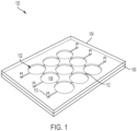
- FIG. 1 is a non-limiting example, and is a perspective view of an array of micromachined ultrasonic transducers comprising pressure ports for access to cavities of the micromachined ultrasonic transducer.
- the ultrasound device 100 comprises an array of nine MUTs 102, formed by a membrane 104, insulating layer 106, and cavities 108.
- Pressure ports 110 are provided, and channels 112 interconnect the cavities 108.
- insulating layer 106 may be a part of a complementary metal-oxide-semiconductor (CMOS) wafer, and cavities 108 can be formed in insulating layer 106 of the CMOS wafer.
- CMOS complementary metal-oxide-semiconductor
- the pressure ports 110 may have any suitable location. In the illustrated non-limiting example, they are positioned at the periphery of the array, and in this non-limiting example on two opposite side of the periphery of the array. When the pressure ports are disposed at the periphery of the array, as shown, control over the cavity pressure of the cavities internal to the array may still be achieved because of the presence of channels 112, which may be air channels.
- channels 112 which may be air channels.
- a pressure port may be provided for each individual cavity as shown in other embodiments. Alternatively, fewer pressure ports may be provided than shown, with additional channels 112 provided to allow for control of the cavity pressure across the array.
- the pressure ports 110 are positioned on two opposite sides of the array. In this non-limiting example, two pressure ports are positioned on a line bisecting the ultrasonic transducers in a given row. However, alternative positioning of pressure ports is possible.
- the pressure ports may have any suitable dimensions and may be formed in any suitable manner. In some embodiments, the pressure ports are sufficiently small to not have a negative impact on the performance of the ultrasonic transducers. Also, the pressure ports may be sufficiently small to allow them to be sealed once the pressures of cavities 108 are set to a desired value.
- the pressure ports may have diameters between approximately 0.1 microns and 20 microns, including any value or range of values within that range.
- the pressure ports may be sealed in any suitable manner, such as with a metal material. For example, aluminum may be sputtered to seal the pressure ports.
- the pressure ports may be created and used during manufacture of the MUT(s).
- the sealed cavities may be formed using a wafer bonding technique.
- the wafer bonding technique may be inadequate for achieving uniform cavity pressure across a wafer or array of MUTs.
- the chemicals present for wafer bonding may unequally occupy or remain in certain cavities of an array of MUTs.
- the pressure ports may be opened.
- the pressures of the sealed cavities may then be equalized, or made substantially equal, through exposure of the wafer to a desired, controlled pressure.
- desired chemicals e.g., Argon
- desired chemicals e.g., Argon
- control of the pressure and/or chemical content of the sealed cavities of a plurality of MUTs may be improved through use of a pressure port.
- the pressure port may provide greater control over these parameters than the wafer bonding process used for forming the sealed cavities.
- FIG. 2 illustrates a top view of the cavity layer of the ultrasound device 100 of FIG. 1 .
- the channels 112 may be air channels, allowing pressure in the adjoining cavities to be set at a uniform level.
- the channels 112 may have any suitable dimensions for this purpose, such as being between 0.1 microns and 20 microns, including any value or range of values within that range.
- FIGs. 1 and 2 The ultrasound device of FIGs. 1 and 2 is a non-limiting example.
- the number of micromachined ultrasonic transducers shown, the shape, dimensions, and positioning are all variables.
- FIG. 2 illustrates circular cavities, but other shapes are possible, such as polygonal, square, or any other suitable shape.
- the positioning and number of pressure ports shown may also be selected for a particular application.
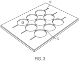
- FIG. 3 illustrates a perspective view of the cavity layer of the device of FIG. 1 including cavities and channels.
- the membrane layer of the ultrasound device 100 is omitted.
- the cavities 108, channels 112, and part of the pressure ports 110 may be formed, for example by etching.
- the membrane 104 may be formed to seal the cavities 108 by creating a membrane layer.
- a vertical part of the pressure ports 110 may then be etched through the membrane 104 to form the ultrasound device 100.
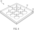
- an array of ultrasonic transducers comprises an array of cavities with respective pressure ports.
- FIG. 4 illustrates an example, representing an alternative to FIG. 1 and having an array of ultrasonic transducers with respective pressure ports.
- the ultrasound device 400 includes the cavities 108, membrane 104, and insulating layer 106.
- One pressure port is provided for each cavity 108 in this non-limiting embodiment.
- the cavities are not interconnected by channels 112. Also, in this non-limiting example it is seen that the pressure ports are all oriented at a common angle relative to the cavities, and are not all disposed at a periphery of the cavity array.
- FIG. 5 is a schematic top view of the cavity layer of the structure of FIG. 4 .
- the cavities 108 include pressure ports 110 which include both a portion in-plane with the cavities and a portion perpendicular to the cavities (represented by the circles at the end of the portion in-plane with the cavities).
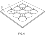
- FIG. 6 illustrates the cavity layer of FIG. 4 including cavities 108 and pressure ports 110.
- the portion of the pressure ports in-plane with the cavities is illustrated.
- the portion of the pressure portions extending upward, perpendicular to the cavities 108 is not shown since that portion extends through the membrane 104, which is not part of FIG. 6 .
- the cavities 108 and portions of the pressure ports 110 in-plane with the cavities 108 may be formed in any suitable manner.
- any suitable technique for etching the insulating layer 106 may be used to form the cavities 108 and in-plane portions of the pressure ports 110.
- the ultrasound device 400 of FIG. 4 may be formed from the structure of FIG. 6 by forming the membrane 104 and etching vertical portions of the pressure ports 110.
- FIGs. 1 and 4 illustrate two non-limiting examples.
- FIG. 7 illustrates a further alternative.
- two pressure ports are provided for each cavity. Providing more than one pressure port per cavity may make it easier to remove undesirable elements from the cavity, such as water or other elements. Having more than one port per cavity may also facilitate achieving a desired pressure for the cavity.
- the pressure ports are represented by the channels, or extensions, with the openings 702 at the end. It can be seen that the pressure ports 110 are oriented at an angle ⁇ with respect to the elevation direction. That angle may be between 5 degrees and 40 degrees, or any other suitable number. Also shown in FIG.
- metal lines 704 and 706 are metal lines 704 and 706.
- Metal lines 704 run in the azimuth direction, while metal lines 706 run in the elevation direction.
- the metal lines 704 and 706 may represent conductive traces for providing signals to/from the ultrasonic transducers.
- the metal of the metal lines may seal the ends of the pressure ports. For example, sputtering aluminum to form the metal lines may seal the pressure ports.
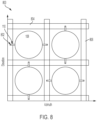
- FIG. 8 illustrates an alternative array of ultrasonic transducers and pressure ports comprising two pressure ports per ultrasonic transducer.
- the illustrated ultrasound device 800 differs from that of FIG. 7 in that the pressure ports for neighboring cavities are oriented differently than each other. In this example, when the pressure ports for a given cavity are oriented along the azimuth direction, the pressure ports for its immediately neighboring cavities are oriented along the elevation direction, and vice versa.
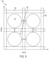
- FIG. 9 illustrates an alternative array of ultrasonic transducers and pressure ports in which, according to the invention, the pressure ports are shared among the ultrasonic transducers.
- the ultrasound device 900 includes cavities 108, metal lines 904 and 906, channels 110 and access holes 902.
- the pressure ports may represent a combination of channels 110 and access holes 902.
- the access holes may extend vertically, for example perpendicular to the cavities 108, as shown in FIG. 9 as openings 902.
- the channels 110 may interconnect neighboring cavities 108 as shown.
- the same number of pressure ports and cavities are provided, and, according to the invention, the pressure ports are accessible internal to the array as opposed to being disposed at a periphery of the array.
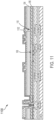
- FIG. 10 is a cross-sectional view 10 of a pressure port of a type which may be used in the device of FIG. 9 .
- each pressure port includes a vertical portion represented by 902, having a width X1 , and an in-plane portion, or channel, with a width X2.
- the value of X1 may be selected so as to be sufficiently small to not negatively impact operation of the ultrasonic transducer, and also to be sufficiently small to allow easy filling.
- X1 may assume any of the value described previously herein with respect to pressure port and access hole dimensions, such as being between 0.1 microns and 20 microns.
- the value of X2 may likewise assume any such value. In the illustrated example, X1 is less than X2.
- membrane 104 may be formed of one or more layers with different material compositions.
- Membrane 104 may be formed from a silicon on insulator (SOI) wafer.
- the SOI wafer may comprise several layers, including but not limited to a buried oxide (BOX) layer 104a, a single crystalline layer 104b, and a thermal oxide layer 104c.
- the SOI wafer may further comprise a handling wafer, which is removed after wafer bonding by any suitable technique such as chemical-mechanical polishing (CMP).
- BOX layer 104a may be any suitable thickness, such as being between 0.5 and 2 microns thick or any other suitable value.
- Single crystalline layer 104b may be single crystalline Si or any suitable single crystalline material.
- Single crystalline layer 104b may also be any suitable thickness to enable operation of the MUTs, including being between 4 and 10 microns thick.
- Thermal oxide layer 104c may be any suitable thickness, such as being between 100 and 300 nm thick.
- FIG. 11 is a cross-sectional view of a non-limiting example of a MUT 1100 having a cavity 108 and pressure port 110.
- the pressure port may be sealed, and thus the illustrated device may represent the state of the device after the cavity pressure has been set to a desired value. At that point, the pressure port may be sealed with seal 1102 to provide a substantially constant pressure within the sealed cavity as a function of time.
- cavities 108, pressure ports 110, and/or channels 112 are formed in insulating layer 106.
- Cavities 108, pressure ports 110, and/or channels 112 may be formed by any suitable etch process including reactive ion etching (RIE), deep reactive ion etching (DRIE), ion milling, plasma etching, or any other suitable method.
- Insulating layer 106 may be a part of a larger CMOS wafer such that the cavities are electrically coupled to other elements of the CMOS wafer.
- the insulating layer 106 with features may be wafer bonded to a membrane wafer, which may be an SOI wafer of the type discussed previously.
- the wafer bonding process may be a low temperature wafer bonding process.
- the wafer bonding process may also include a post-process annealing step. During annealing, gettering materials may be present to help control the pressure inside the cavities 108. For example, gettering materials might include Ti, TiN, SrO, and/or Zr-Al.
- the handling wafer of the membrane wafer may be ground off, allowing the membrane 104 above the cavities 108 to flex.
- the handling wafer may be ground off in any suitable way including chemical-mechanical polishing.
- openings such as openings 902 are formed to open pressure ports 110, allowing the pressure of the cavities 108 to equalize. Openings may be formed using any suitable etch process such as RIE and/or DRIE. In some embodiments, RIE is first used to etch through BOX layer 104a. Then, DRIE is used to etch single crystalline layer 104b, and RIE is again used to etch through thermal oxide layer 104c. Since the pressure ports 110 are opened under vacuum, any outgassed materials from the wafer bonding and/or annealing processes escape during act 1208, and the pressure of the cavities 108 equalizes to that of the vacuum chamber.
- RIE is first used to etch through BOX layer 104a. Then, DRIE is used to etch single crystalline layer 104b, and RIE is again used to etch through thermal oxide layer 104c. Since the pressure ports 110 are opened under vacuum, any outgassed materials from the wafer bonding and/or annealing processes escape during act 1208, and the pressure of the cavities 108 equal
- the pressure ports 110 are sealed so that the cavities 108 may remain at a suitable pressure for operation.
- the pressure ports 110 may be sealed by any suitable material, or by any suitable process such as but not limited to a sputtering process.
- the pressure ports 110 may be sealed by a multilayered structure formed of multiple materials. Example materials include Al, Cu, Al/Cu alloys, and TiN in any suitable combination.
- the micromachined ultrasonic transducers described herein may be of various types. In some embodiments, they may be capacitive micromachined ultrasonic transducers (CMUTs). In such situations, they may be formed by wafer bonding or sacrificial release methods. In some embodiments, the micromachined ultrasonic transducers are piezoelectric micromachined ultrasonic transducers (PMUTs).
- CMUTs capacitive micromachined ultrasonic transducers
- PMUTs piezoelectric micromachined ultrasonic transducers
- a handheld ultrasound probe may include an ultrasound-on-a-chip comprising MUTs with pressure ports.
- an ultrasound patch may implement the technology.
- a pill may also utilize the technology.
- some aspects may be embodied as one or more methods.
- the acts performed as part of the method(s) may be ordered in any suitable way. Accordingly, embodiments may be constructed in which acts are performed in an order different than illustrated, which may include performing some acts simultaneously, even though shown as sequential acts in illustrative embodiments.
- the phrase "at least one,” in reference to a list of one or more elements, should be understood to mean at least one element selected from any one or more of the elements in the list of elements, but not necessarily including at least one of each and every element specifically listed within the list of elements and not excluding any combinations of elements in the list of elements.
- the terms “approximately” and “about” may be used to mean within ⁇ 20% of a target value in some embodiments, within ⁇ 10% of a target value in some embodiments, within ⁇ 5% of a target value in some embodiments, and yet within ⁇ 2% of a target value in some embodiments.
- the terms “approximately” and “about” may include the target value.
Description
- The present application relates to micromachined ultrasonic transducers.
- Some micromachined ultrasonic transducers include a flexible membrane suspended above a substrate. A cavity is located between part of the substrate and the membrane, such that the combination of the substrate, cavity, and membrane form a variable capacitor. If actuated, the membrane may generate an ultrasound signal. In response to receiving an ultrasound signal, the membrane may vibrate, resulting in an output electrical signal.
-
US 2016/107194 A1 discloses a piezoelectric micromechanical ultrasonic transducer (PMUT) including a diaphragm disposed over a cavity, the diaphragm including a piezoelectric layer stack including a piezoelectric layer, a first electrode electrically coupled with transceiver circuitry, and a second electrode electrically coupled with the transceiver circuitry. The first electrode may be disposed in a first portion of the diaphragm, and the second electrode may be disposed in a second, separate, portion of the diaphragm. Each of the first and the second electrode is disposed on or proximate to a first surface of the piezoelectric layer, the first surface being opposite from the cavity. The cavity is accessible by a plurality of pressure ports, which are used to set a pressure inside the cavity and sealed after the desired pressure is reached. The PMUT may be arranged in an array of a plurality of PMUTs. - The PMUT is configured to transmit first ultrasonic signals by way of the first electrode during a first time period and to receive second ultrasonic signals by way of the second electrode during a second time period, the first time period and the second time period being at least partially overlapping.
-
US 2012/086087 A1 discloses a multi-layer stacked micro-electro-mechanical (MEMS) device that acts as a capacitive micromachined ultrasonic transducer (CMUT) with a hermetically sealed device cavity formed by a wafer bonding process with semiconductor and insulator layers. The CMUT design uses a doped Si SOI and wafer bonding fabrication method, and is composed of semiconductor layers, insulator layers, and metal layers. Conventional doped silicon may be used for electrode layers. Other suitable semi-conductor materials such as silicon carbide may be used for the electrode layers. The insulator may be silicon oxide, silicon nitride or other suitable dielectric. -
US 2017/110504 A1 discloses an ultrasonic sensor pixel including a substrate, a piezoelectric micromechanical ultrasonic transducer (PMUT) and a sensor pixel circuit. The PMUT includes a piezoelectric layer stack including a piezoelectric layer disposed over a cavity, the cavity being disposed between the piezoelectric layer stack and the substrate, a reference electrode disposed between the piezoelectric layer and the cavity, and one or both of a receive electrode and a transmit electrode disposed on or proximate to a first surface of the piezoelectric layer, the first surface being opposite from the cavity. The sensor pixel circuit is electrically coupled with one or more of the reference electrode, the receive electrode and the transmit electrode and the PMUT and the sensor pixel circuit are integrated with the sensor pixel circuit on the substrate. - According to one aspect of the present invention, an ultrasound device is provided in accordance with claim 1.
- Various aspects and embodiments of the application will be described with reference to the following figures. It should be appreciated that the figures are not necessarily drawn to scale. Items appearing in multiple figures are indicated by the same reference number in all the figures in which they appear.
-
FIG. 1 is a perspective view of an array of micromachined ultrasonic transducers comprising pressure ports for access to cavities of the micromachined ultrasonic transducer. -
FIG. 2 is a schematic top view of the cavity layer of the structure ofFIG. 1 . -
FIG. 3 illustrates a layer of the device ofFIG. 1 including cavities and channels. -
FIG. 4 illustrates an alternative toFIG. 1 having an array of ultrasonic transducers with respective pressure ports. -
FIG. 5 is a schematic top view of the cavity layer of the structure ofFIG. 4 . -
FIG. 6 illustrates the cavity layer ofFIG. 4 including cavities and portions of the pressure ports. -
FIG. 7 illustrates an alternative array of ultrasonic transducers and pressure ports comprising two pressure ports per ultrasonic transducer. -
FIG. 8 illustrates an alternative array of ultrasonic transducers and pressure ports comprising two pressure ports per ultrasonic transducer. -
FIG. 9 illustrates an alternative array of ultrasonic transducers and pressure ports in which the pressure ports are shared among the ultrasonic transducers. -
FIG. 10 is a cross-sectional view of a pressure port of a type which may be used in the device ofFIG. 9 . -
FIG. 11 is a cross-sectional view of a non-limiting example of a micromachined ultrasonic transducer having a pressure port. -
FIG. 12 is a flowchart of a fabrication process for forming an ultrasonic transducer having a pressure port, according to some embodiments. - Aspects of the present invention provide an array of thousands of micromachined ultrasonic transducers (MUTs) comprising a plurality of pressure ports. The array of MUTs includes a plurality of sealed cavities, for example sealed on a top and bottom side by a membrane and a substrate, respectively. The pressure ports are accessible internal to the array of MUTs. The pressure ports function to control the pressure within the sealed cavity during manufacture of the MUT. Once the pressure of the cavity, or cavities, is set as desired, the pressure port may be sealed. The substrate may be bonded with an integrated circuit substrate comprising integrated circuitry. Alternatively, the substrate may comprise integrated circuitry.
- The inclusion of a pressure port for a MUT may provide various benefits. The pressure port may allow for control of the pressure of the sealed cavity of the MUT. Some ultrasound devices comprise large numbers of MUTs, such as hundreds, thousands, or hundreds of thousands of MUTs. Operation of such ultrasound devices may benefit in terms of accuracy and dynamic range (e.g., by minimizing damping) from having a substantially equal or uniform pressure across the area of the MUTs. Thus, providing pressure ports for individual MUTs or sub-groups of MUTs of the ultrasound device may facilitate achieving more uniform pressure across the sensing area. The pressure ports may allow for equalization of cavity pressure over a sensing area comprising multiple MUTs. The pressure ports may be used during manufacture, and sealed after the cavities are equalized in terms of pressure.
- Various characteristics of ultrasonic transducer pressure ports may be selected according to aspects of the present application. According to some aspects, each ultrasonic transducer may have one or more respective pressure ports. According to the invention, a pressure port is shared by two or more ultrasonic transducers. According to an aspect of the present application, an array of ultrasonic transducer may include respective pressure ports oriented at a same angle as each other relative to the array. According to alternative aspects, an array of ultrasonic transducers may include respective pressure ports, in which two or more of the pressure ports are oriented at different angles relative to the array. The number of pressure ports provided for an array of ultrasonic transducers may be less than, equal to, or greater than the number of ultrasonic transducers. Further variations are possible.
- The aspects and embodiments described above, as well as additional aspects and embodiments, are described further below. These aspects and/or embodiments may be used individually, all together, or in any combination of two or more, as the application is not limited in this respect.
- According to an aspect of the present application, pressure ports are provided for an array of ultrasonic transducers. In some embodiments, the ultrasonic transducers include sealed cavities connected to each other by interconnection channels, and according to the invention, a plurality of pressure ports are shared by the array of ultrasonic transducers.
FIG. 1 is a non-limiting example, and is a perspective view of an array of micromachined ultrasonic transducers comprising pressure ports for access to cavities of the micromachined ultrasonic transducer. Theultrasound device 100 comprises an array of nineMUTs 102, formed by amembrane 104, insulatinglayer 106, andcavities 108.Pressure ports 110 are provided, andchannels 112 interconnect thecavities 108. In some embodiments, insulatinglayer 106 may be a part of a complementary metal-oxide-semiconductor (CMOS) wafer, andcavities 108 can be formed in insulatinglayer 106 of the CMOS wafer. - The
pressure ports 110 may have any suitable location. In the illustrated non-limiting example, they are positioned at the periphery of the array, and in this non-limiting example on two opposite side of the periphery of the array. When the pressure ports are disposed at the periphery of the array, as shown, control over the cavity pressure of the cavities internal to the array may still be achieved because of the presence ofchannels 112, which may be air channels. However, alternative configurations are possible. For example, a pressure port may be provided for each individual cavity as shown in other embodiments. Alternatively, fewer pressure ports may be provided than shown, withadditional channels 112 provided to allow for control of the cavity pressure across the array. - Various characteristics of the
pressure ports 110 may be noted, including positioning and size. In the non-limiting example shown, thepressure ports 110 are positioned on two opposite sides of the array. In this non-limiting example, two pressure ports are positioned on a line bisecting the ultrasonic transducers in a given row. However, alternative positioning of pressure ports is possible. The pressure ports may have any suitable dimensions and may be formed in any suitable manner. In some embodiments, the pressure ports are sufficiently small to not have a negative impact on the performance of the ultrasonic transducers. Also, the pressure ports may be sufficiently small to allow them to be sealed once the pressures ofcavities 108 are set to a desired value. For example, the pressure ports may have diameters between approximately 0.1 microns and 20 microns, including any value or range of values within that range. The pressure ports may be sealed in any suitable manner, such as with a metal material. For example, aluminum may be sputtered to seal the pressure ports. - The pressure ports may be created and used during manufacture of the MUT(s). In some embodiments, the sealed cavities may be formed using a wafer bonding technique. The wafer bonding technique may be inadequate for achieving uniform cavity pressure across a wafer or array of MUTs. Also, the chemicals present for wafer bonding may unequally occupy or remain in certain cavities of an array of MUTs. After the cavities are sealed (for example, by the wafer bonding), the pressure ports may be opened. The pressures of the sealed cavities may then be equalized, or made substantially equal, through exposure of the wafer to a desired, controlled pressure. Also, desired chemicals (e.g., Argon) may be introduced to the cavities through the pressure ports. Subsequently, the pressure ports may be sealed.
- Thus, the inventors have appreciated that control of the pressure and/or chemical content of the sealed cavities of a plurality of MUTs may be improved through use of a pressure port. The pressure port may provide greater control over these parameters than the wafer bonding process used for forming the sealed cavities.
-
FIG. 2 illustrates a top view of the cavity layer of theultrasound device 100 ofFIG. 1 . As shown, nine cavities are included, interconnected bychannels 112. Again, thechannels 112 may be air channels, allowing pressure in the adjoining cavities to be set at a uniform level. Thechannels 112 may have any suitable dimensions for this purpose, such as being between 0.1 microns and 20 microns, including any value or range of values within that range. - The ultrasound device of
FIGs. 1 and2 is a non-limiting example. The number of micromachined ultrasonic transducers shown, the shape, dimensions, and positioning are all variables. For example,FIG. 2 illustrates circular cavities, but other shapes are possible, such as polygonal, square, or any other suitable shape. The positioning and number of pressure ports shown may also be selected for a particular application. -
FIG. 3 illustrates a perspective view of the cavity layer of the device ofFIG. 1 including cavities and channels. In this figure, the membrane layer of theultrasound device 100 is omitted. Thecavities 108,channels 112, and part of thepressure ports 110 may be formed, for example by etching. Subsequently, themembrane 104 may be formed to seal thecavities 108 by creating a membrane layer. A vertical part of thepressure ports 110 may then be etched through themembrane 104 to form theultrasound device 100. - As described previously, the number and positioning of pressure ports provided with an array of ultrasonic transducers may be different than that shown in
FIG. 1 . According to an aspect of the present application, an array of ultrasonic transducers comprises an array of cavities with respective pressure ports.FIG. 4 illustrates an example, representing an alternative toFIG. 1 and having an array of ultrasonic transducers with respective pressure ports. Theultrasound device 400 includes thecavities 108,membrane 104, and insulatinglayer 106. One pressure port is provided for eachcavity 108 in this non-limiting embodiment. In addition, the cavities are not interconnected bychannels 112. Also, in this non-limiting example it is seen that the pressure ports are all oriented at a common angle relative to the cavities, and are not all disposed at a periphery of the cavity array. -
FIG. 5 is a schematic top view of the cavity layer of the structure ofFIG. 4 . As shown, thecavities 108 includepressure ports 110 which include both a portion in-plane with the cavities and a portion perpendicular to the cavities (represented by the circles at the end of the portion in-plane with the cavities). -
FIG. 6 illustrates the cavity layer ofFIG. 4 includingcavities 108 andpressure ports 110. In this view, the portion of the pressure ports in-plane with the cavities is illustrated. The portion of the pressure portions extending upward, perpendicular to thecavities 108 is not shown since that portion extends through themembrane 104, which is not part ofFIG. 6 . Thecavities 108 and portions of thepressure ports 110 in-plane with thecavities 108 may be formed in any suitable manner. For example, any suitable technique for etching the insulatinglayer 106 may be used to form thecavities 108 and in-plane portions of thepressure ports 110. Theultrasound device 400 ofFIG. 4 may be formed from the structure ofFIG. 6 by forming themembrane 104 and etching vertical portions of thepressure ports 110. - As described previously, various configurations of pressure ports may be used with an array of ultrasonic transducers.
FIGs. 1 and4 illustrate two non-limiting examples.FIG. 7 illustrates a further alternative. In the non-limiting example ofFIG. 7 , two pressure ports are provided for each cavity. Providing more than one pressure port per cavity may make it easier to remove undesirable elements from the cavity, such as water or other elements. Having more than one port per cavity may also facilitate achieving a desired pressure for the cavity. In theultrasound device 700, the pressure ports are represented by the channels, or extensions, with theopenings 702 at the end. It can be seen that thepressure ports 110 are oriented at an angle Θ with respect to the elevation direction. That angle may be between 5 degrees and 40 degrees, or any other suitable number. Also shown inFIG. 7 aremetal lines Metal lines 704 run in the azimuth direction, whilemetal lines 706 run in the elevation direction. Themetal lines FIG. 7 terminate at metal lines oriented in the azimuth direction. The metal of the metal lines may seal the ends of the pressure ports. For example, sputtering aluminum to form the metal lines may seal the pressure ports. -
FIG. 8 illustrates an alternative array of ultrasonic transducers and pressure ports comprising two pressure ports per ultrasonic transducer. The illustratedultrasound device 800 differs from that ofFIG. 7 in that the pressure ports for neighboring cavities are oriented differently than each other. In this example, when the pressure ports for a given cavity are oriented along the azimuth direction, the pressure ports for its immediately neighboring cavities are oriented along the elevation direction, and vice versa. -
FIG. 9 illustrates an alternative array of ultrasonic transducers and pressure ports in which, according to the invention, the pressure ports are shared among the ultrasonic transducers. Theultrasound device 900 includescavities 108,metal lines channels 110 and access holes 902. The pressure ports may represent a combination ofchannels 110 and access holes 902. The access holes may extend vertically, for example perpendicular to thecavities 108, as shown inFIG. 9 asopenings 902. Thechannels 110 may interconnect neighboringcavities 108 as shown. In this example, the same number of pressure ports and cavities are provided, and, according to the invention, the pressure ports are accessible internal to the array as opposed to being disposed at a periphery of the array. -
FIG. 10 is a cross-sectional view 10 of a pressure port of a type which may be used in the device ofFIG. 9 . According to the invention, each pressure port includes a vertical portion represented by 902, having a width X1 , and an in-plane portion, or channel, with a width X2. The value of X1 may be selected so as to be sufficiently small to not negatively impact operation of the ultrasonic transducer, and also to be sufficiently small to allow easy filling. In some embodiments, X1 may assume any of the value described previously herein with respect to pressure port and access hole dimensions, such as being between 0.1 microns and 20 microns. The value of X2 may likewise assume any such value. In the illustrated example, X1 is less than X2. - In some embodiments,
membrane 104 may be formed of one or more layers with different material compositions.Membrane 104 may be formed from a silicon on insulator (SOI) wafer. The SOI wafer may comprise several layers, including but not limited to a buried oxide (BOX)layer 104a, asingle crystalline layer 104b, and athermal oxide layer 104c. The SOI wafer may further comprise a handling wafer, which is removed after wafer bonding by any suitable technique such as chemical-mechanical polishing (CMP).BOX layer 104a may be any suitable thickness, such as being between 0.5 and 2 microns thick or any other suitable value.Single crystalline layer 104b may be single crystalline Si or any suitable single crystalline material.Single crystalline layer 104b may also be any suitable thickness to enable operation of the MUTs, including being between 4 and 10 microns thick.Thermal oxide layer 104c may be any suitable thickness, such as being between 100 and 300 nm thick. -
FIG. 11 is a cross-sectional view of a non-limiting example of aMUT 1100 having acavity 108 andpressure port 110. As shown, the pressure port may be sealed, and thus the illustrated device may represent the state of the device after the cavity pressure has been set to a desired value. At that point, the pressure port may be sealed withseal 1102 to provide a substantially constant pressure within the sealed cavity as a function of time. - The fabrication process of a MUT like
MUT 1100 is described byprocess 1200 ofFIG. 12 . First, inact 1202, features such as but not limited tocavities 108,pressure ports 110, and/orchannels 112 are formed in insulatinglayer 106.Cavities 108,pressure ports 110, and/orchannels 112 may be formed by any suitable etch process including reactive ion etching (RIE), deep reactive ion etching (DRIE), ion milling, plasma etching, or any other suitable method. Insulatinglayer 106 may be a part of a larger CMOS wafer such that the cavities are electrically coupled to other elements of the CMOS wafer. - In
act 1204, the insulatinglayer 106 with features may be wafer bonded to a membrane wafer, which may be an SOI wafer of the type discussed previously. The wafer bonding process may be a low temperature wafer bonding process. The wafer bonding process may also include a post-process annealing step. During annealing, gettering materials may be present to help control the pressure inside thecavities 108. For example, gettering materials might include Ti, TiN, SrO, and/or Zr-Al. Inact 1206, the handling wafer of the membrane wafer may be ground off, allowing themembrane 104 above thecavities 108 to flex. The handling wafer may be ground off in any suitable way including chemical-mechanical polishing. - In
act 1208, openings such asopenings 902 are formed to openpressure ports 110, allowing the pressure of thecavities 108 to equalize. Openings may be formed using any suitable etch process such as RIE and/or DRIE. In some embodiments, RIE is first used to etch throughBOX layer 104a. Then, DRIE is used to etchsingle crystalline layer 104b, and RIE is again used to etch throughthermal oxide layer 104c. Since thepressure ports 110 are opened under vacuum, any outgassed materials from the wafer bonding and/or annealing processes escape duringact 1208, and the pressure of thecavities 108 equalizes to that of the vacuum chamber. - In
act 1210, thepressure ports 110 are sealed so that thecavities 108 may remain at a suitable pressure for operation. Thepressure ports 110 may be sealed by any suitable material, or by any suitable process such as but not limited to a sputtering process. Thepressure ports 110 may be sealed by a multilayered structure formed of multiple materials. Example materials include Al, Cu, Al/Cu alloys, and TiN in any suitable combination. - The micromachined ultrasonic transducers described herein may be of various types. In some embodiments, they may be capacitive micromachined ultrasonic transducers (CMUTs). In such situations, they may be formed by wafer bonding or sacrificial release methods. In some embodiments, the micromachined ultrasonic transducers are piezoelectric micromachined ultrasonic transducers (PMUTs).
- Various types of ultrasound devices may implement MUTs with pressure ports of the types described herein. In some embodiments, a handheld ultrasound probe may include an ultrasound-on-a-chip comprising MUTs with pressure ports. In some embodiments, an ultrasound patch may implement the technology. A pill may also utilize the technology. Thus, aspects of the present application provide for such ultrasound devices to include MUTs with pressure ports.
- Having thus described several aspects and embodiments of the technology of this application, it is to be appreciated that various alterations, modifications, and improvements will readily occur to those of ordinary skill in the art. It is, therefore, to be understood that the foregoing embodiments are presented by way of example only and that the scope of the invention is defined by the appended claims.
- As described, some aspects may be embodied as one or more methods. The acts performed as part of the method(s) may be ordered in any suitable way. Accordingly, embodiments may be constructed in which acts are performed in an order different than illustrated, which may include performing some acts simultaneously, even though shown as sequential acts in illustrative embodiments.
- All definitions, as defined and used herein, should be understood to control over dictionary definitions, and/or ordinary meanings of the defined terms.
- The phrase "and/or," as used herein in the specification and in the claims, should be understood to mean "either or both" of the elements so conjoined, i.e., elements that are conjunctively present in some cases and disjunctively present in other cases.
- As used herein in the specification and in the claims, the phrase "at least one," in reference to a list of one or more elements, should be understood to mean at least one element selected from any one or more of the elements in the list of elements, but not necessarily including at least one of each and every element specifically listed within the list of elements and not excluding any combinations of elements in the list of elements.
- As used herein, the term "between" used in a numerical context is to be inclusive unless indicated otherwise. For example, "between A and B" includes A and B unless indicated otherwise.
- The terms "approximately" and "about" may be used to mean within ±20% of a target value in some embodiments, within ±10% of a target value in some embodiments, within ±5% of a target value in some embodiments, and yet within ±2% of a target value in some embodiments. The terms "approximately" and "about" may include the target value.
Claims (15)
- An ultrasound device (100) comprising:an array of thousands of micromachined ultrasonic transducers (102) anda plurality of pressure ports (110) shared by the array of micromachined ultrasonic transducers, wherein the plurality of pressure ports are accessible internal to the array of micromachined ultrasonic transducers,wherein the array of micromachined ultrasonic transducers comprises: a plurality of sealed cavities (108), andwherein the plurality of pressure ports are configured to control a pressure of the sealed cavities, wherein each pressure port of the plurality of pressure ports comprises a portion in-plane with the plurality of sealed cavities and a portion substantially perpendicular to the plurality of sealed cavities.
- The ultrasound device of claim 1, wherein the substantially perpendicular portion is thinner than the in-plane portion.
- The ultrasound device of claim 1, wherein each pressure port of the plurality of pressure ports is part of a channel (110) interconnecting two sealed cavities of the plurality of sealed cavities.
- The ultrasound device of claim 1, wherein each pressure port of the plurality of pressure ports comprises a 90-degree bend.
- The ultrasound device of claim 1, wherein each micromachined ultrasonic transducer of the array of micromachined ultrasonic transducers comprises at least one of a capacitive micromachined ultrasonic transducer and a piezoelectric micromachined ultrasonic transducer.
- The ultrasound device of claim 1, wherein the array of micromachined ultrasonic transducers is disposed in a handheld ultrasound probe.
- The ultrasound device of claim 1, wherein each pressure port of the plurality of pressure ports is sealed at one end.
- The ultrasound device of claim 7, wherein each pressure port of the plurality of pressure ports is sealed by a metal.
- The ultrasound device of claim 7, wherein each pressure port of the plurality of pressure ports is substantially free of solid material.
- The ultrasound device of claim 7, wherein each pressure port of the plurality of pressure ports comprises a void.
- The ultrasound device of claim 10, wherein the void is filled with a gas.
- The ultrasound device of claim 1, wherein the substantially perpendicular portion projects substantially perpendicular to along axis of the plurality of sealed cavities.
- The ultrasound device of claim 1, wherein each micromachined ultrasonic transducer of the array of micromachined ultrasonic transducers further comprises a substrate and a membrane (104), wherein the substrate and the membrane are positioned with a sealed cavity of the plurality of sealed cavities between them, and wherein a pressure port of the plurality of pressure ports is through the membrane.
- The ultrasound device of claim 13, wherein the substrate is bonded with an integrated circuit substrate comprising integrated circuitry.
- The ultrasound device of claim 13, wherein the substrate comprises integrated circuitry.
Applications Claiming Priority (3)
| Application Number | Priority Date | Filing Date | Title |
|---|---|---|---|
| US201862666556P | 2018-05-03 | 2018-05-03 | |
| US201862696305P | 2018-07-10 | 2018-07-10 | |
| PCT/US2019/030388 WO2019213388A1 (en) | 2018-05-03 | 2019-05-02 | Pressure port for ultrasonic transducer on cmos sensor |
Publications (4)
| Publication Number | Publication Date |
|---|---|
| EP3788798A1 EP3788798A1 (en) | 2021-03-10 |
| EP3788798A4 EP3788798A4 (en) | 2022-01-19 |
| EP3788798C0 EP3788798C0 (en) | 2023-07-05 |
| EP3788798B1 true EP3788798B1 (en) | 2023-07-05 |
Family
ID=68384340
Family Applications (1)
| Application Number | Title | Priority Date | Filing Date |
|---|---|---|---|
| EP19795861.4A Active EP3788798B1 (en) | 2018-05-03 | 2019-05-02 | Ultrasonic transducers with pressure ports |
Country Status (9)
| Country | Link |
|---|---|
| US (1) | US20190336099A1 (en) |
| EP (1) | EP3788798B1 (en) |
| JP (1) | JP2021522734A (en) |
| KR (1) | KR20210005208A (en) |
| CN (1) | CN112075090B (en) |
| AU (1) | AU2019263404A1 (en) |
| CA (1) | CA3098911A1 (en) |
| TW (1) | TW202000137A (en) |
| WO (1) | WO2019213388A1 (en) |
Families Citing this family (13)
| Publication number | Priority date | Publication date | Assignee | Title |
|---|---|---|---|---|
| WO2016106153A1 (en) * | 2014-12-21 | 2016-06-30 | Chirp Microsystems, Inc. | Piezoelectric micromachined ultrasonic transducers with low stress sensitivity and methods of fabrication |
| EP3856679B1 (en) | 2018-09-28 | 2024-05-01 | BFLY Operations, Inc. | Fabrication techniques and structures for gettering materials in ultrasonic transducer cavities |
| CA3118563A1 (en) | 2018-11-13 | 2020-05-22 | Butterfly Network, Inc. | Getter technology for micromachined ultrasonic transducer cavities |
| EP3881065B1 (en) | 2018-11-15 | 2023-07-19 | BFLY Operations, Inc. | Anti-stiction bottom cavity surface for micromachined ultrasonic transducer devices |
| TW202045099A (en) | 2019-02-07 | 2020-12-16 | 美商蝴蝶網路公司 | Bi-layer metal electrode for micromachined ultrasonic transducer devices |
| CN115367696A (en) | 2019-02-25 | 2022-11-22 | 蝴蝶网络有限公司 | Adaptive cavity thickness control for micromachined ultrasonic transducer devices |
| WO2020210470A1 (en) | 2019-04-12 | 2020-10-15 | Butterfly Network, Inc. | Bottom electrode via structures for micromachined ultrasonic transducer devices |
| US11501562B2 (en) | 2019-04-30 | 2022-11-15 | Bfly Operations, Inc. | Ultrasound face scanning and identification apparatuses and methods |
| FR3097091B1 (en) * | 2019-06-07 | 2021-07-23 | Commissariat Energie Atomique | device provided with a plurality of resonators collectively exhibiting an improved quality factor |
| US11684951B2 (en) | 2019-08-08 | 2023-06-27 | Bfly Operations, Inc. | Micromachined ultrasonic transducer devices having truncated circle shaped cavities |
| TWI742603B (en) | 2020-04-09 | 2021-10-11 | 伊諾司生技股份有限公司 | A sensor with a chamber |
| US20210328564A1 (en) | 2020-04-16 | 2021-10-21 | Butterfly Network, Inc. | Methods and circuitry for built-in self-testing of circuitry and/or transducers in ultrasound devices |
| US20210403321A1 (en) * | 2020-06-30 | 2021-12-30 | Butterfly Network, Inc. | Formation of self-assembled monolayer for ultrasonic transducers |
Family Cites Families (23)
| Publication number | Priority date | Publication date | Assignee | Title |
|---|---|---|---|---|
| JPH01296122A (en) * | 1988-05-24 | 1989-11-29 | Matsushita Electric Ind Co Ltd | Pressure sensor |
| US4996627A (en) * | 1989-01-30 | 1991-02-26 | Dresser Industries, Inc. | High sensitivity miniature pressure transducer |
| US5894452A (en) * | 1994-10-21 | 1999-04-13 | The Board Of Trustees Of The Leland Stanford Junior University | Microfabricated ultrasonic immersion transducer |
| US5982709A (en) * | 1998-03-31 | 1999-11-09 | The Board Of Trustees Of The Leland Stanford Junior University | Acoustic transducers and method of microfabrication |
| WO2005120130A1 (en) * | 2004-06-03 | 2005-12-15 | Olympus Corporation | Electrostatic capacity type ultrasonic vibrator, manufacturing method thereof, and electrostatic capacity type ultrasonic probe |
| US6891711B1 (en) * | 2004-04-08 | 2005-05-10 | Kulite Semiconductor Products, Inc. | Ultra-miniature, high temperature, capacitive inductive pressure transducer |
| WO2005114820A2 (en) * | 2004-05-14 | 2005-12-01 | The University Of Georgia Research Foundation, Inc. | Implantable ultrasonic transducer systems and methods |
| US8454513B2 (en) * | 2004-12-30 | 2013-06-04 | Stc.Unm | Micro-machined medical devices, methods of fabricating microdevices, and methods of medical diagnosis, imaging, stimulation, and treatment |
| GB0605576D0 (en) * | 2006-03-20 | 2006-04-26 | Oligon Ltd | MEMS device |
| US7616077B1 (en) * | 2007-03-22 | 2009-11-10 | Sandia Corporation | Microelectromechanical resonator and method for fabrication |
| EP2659987A1 (en) * | 2009-03-26 | 2013-11-06 | Norwegian University of Science and Technology (NTNU) | Acoustic backing layer for use in an ultrasound transducer |
| JP5529577B2 (en) * | 2010-02-14 | 2014-06-25 | キヤノン株式会社 | Electromechanical transducer and method for manufacturing the same |
| WO2012048424A1 (en) * | 2010-10-12 | 2012-04-19 | Micralyne Inc. | Soi-based cmut device with buried electrodes |
| JP5901566B2 (en) * | 2013-04-18 | 2016-04-13 | キヤノン株式会社 | Transducer, transducer manufacturing method, and subject information acquisition apparatus |
| CA2919183A1 (en) * | 2013-07-23 | 2015-01-29 | Butterfly Network, Inc. | Interconnectable ultrasound transducer probes and related methods and apparatus |
| JP2015103821A (en) * | 2013-11-20 | 2015-06-04 | キヤノン株式会社 | Capacitive transducer and manufacturing method thereof |
| WO2015112452A1 (en) * | 2014-01-24 | 2015-07-30 | The Regents Of The University Of California | Curved piezoelectric transducers |
| KR102237662B1 (en) * | 2014-04-18 | 2021-04-09 | 버터플라이 네트워크, 인크. | Ultrasonic transducers in complementary metal oxide semiconductor (cmos) wafers and related apparatus and methods |
| EP3166734A1 (en) * | 2014-07-08 | 2017-05-17 | Qualcomm Incorporated | Piezoelectric ultrasonic transducer and process |
| US9821340B2 (en) * | 2014-07-28 | 2017-11-21 | Kolo Medical Ltd. | High displacement ultrasonic transducer |
| US9995821B2 (en) * | 2014-10-15 | 2018-06-12 | Qualcomm Incorporated | Active beam-forming technique for piezoelectric ultrasonic transducer array |
| WO2016106153A1 (en) * | 2014-12-21 | 2016-06-30 | Chirp Microsystems, Inc. | Piezoelectric micromachined ultrasonic transducers with low stress sensitivity and methods of fabrication |
| US10497748B2 (en) * | 2015-10-14 | 2019-12-03 | Qualcomm Incorporated | Integrated piezoelectric micromechanical ultrasonic transducer pixel and array |
-
2019
- 2019-05-02 CN CN201980029781.8A patent/CN112075090B/en active Active
- 2019-05-02 KR KR1020207034403A patent/KR20210005208A/en not_active Application Discontinuation
- 2019-05-02 CA CA3098911A patent/CA3098911A1/en active Pending
- 2019-05-02 TW TW108115250A patent/TW202000137A/en unknown
- 2019-05-02 EP EP19795861.4A patent/EP3788798B1/en active Active
- 2019-05-02 WO PCT/US2019/030388 patent/WO2019213388A1/en active Application Filing
- 2019-05-02 JP JP2020560488A patent/JP2021522734A/en active Pending
- 2019-05-02 AU AU2019263404A patent/AU2019263404A1/en not_active Abandoned
- 2019-05-02 US US16/401,870 patent/US20190336099A1/en active Pending
Also Published As
| Publication number | Publication date |
|---|---|
| CN112075090B (en) | 2022-10-14 |
| TW202000137A (en) | 2020-01-01 |
| CN112075090A (en) | 2020-12-11 |
| WO2019213388A1 (en) | 2019-11-07 |
| EP3788798A1 (en) | 2021-03-10 |
| JP2021522734A (en) | 2021-08-30 |
| AU2019263404A1 (en) | 2020-11-19 |
| EP3788798C0 (en) | 2023-07-05 |
| EP3788798A4 (en) | 2022-01-19 |
| US20190336099A1 (en) | 2019-11-07 |
| KR20210005208A (en) | 2021-01-13 |
| CA3098911A1 (en) | 2019-11-07 |
Similar Documents
| Publication | Publication Date | Title |
|---|---|---|
| EP3788798B1 (en) | Ultrasonic transducers with pressure ports | |
| EP3132470B1 (en) | Ultrasonic transducers in complementary metal oxide semiconductor (cmos) wafers and related apparatus and methods | |
| US20200266798A1 (en) | Micromachined ultrasound transducer using multiple piezoelectric materials | |
| US7545075B2 (en) | Capacitive micromachined ultrasonic transducer array with through-substrate electrical connection and method of fabricating same | |
| JP5851238B6 (en) | Ultrasonic transducer, its manufacturing method, and ultrasonic probe using the same | |
| US20220369041A1 (en) | Mems device with enhanced membrane structure and method of forming the same | |
| Helin et al. | Poly-SiGe-based CMUT array with high acoustical pressure | |
| TWI732688B (en) | Piezoelectric micromachined ultrasonic transducer and method of fabricating the same | |
| CN114335320A (en) | Piezoelectric micromechanical ultrasonic transducer and manufacturing method thereof | |
| TW202203480A (en) | Piezoelectric micromachined ultrasonic transducer and method of fabricating the same | |
| CN113896165A (en) | Piezoelectric micromechanical ultrasonic transducer and manufacturing method thereof |
Legal Events
| Date | Code | Title | Description |
|---|---|---|---|
| STAA | Information on the status of an ep patent application or granted ep patent |
Free format text: STATUS: THE INTERNATIONAL PUBLICATION HAS BEEN MADE |
|
| STAA | Information on the status of an ep patent application or granted ep patent |
Free format text: STATUS: THE INTERNATIONAL PUBLICATION HAS BEEN MADE |
|
| PUAI | Public reference made under article 153(3) epc to a published international application that has entered the european phase |
Free format text: ORIGINAL CODE: 0009012 |
|
| STAA | Information on the status of an ep patent application or granted ep patent |
Free format text: STATUS: REQUEST FOR EXAMINATION WAS MADE |
|
| 17P | Request for examination filed |
Effective date: 20201104 |
|
| AK | Designated contracting states |
Kind code of ref document: A1 Designated state(s): AL AT BE BG CH CY CZ DE DK EE ES FI FR GB GR HR HU IE IS IT LI LT LU LV MC MK MT NL NO PL PT RO RS SE SI SK SM TR |
|
| AX | Request for extension of the european patent |
Extension state: BA ME |
|
| DAV | Request for validation of the european patent (deleted) | ||
| DAX | Request for extension of the european patent (deleted) | ||
| A4 | Supplementary search report drawn up and despatched |
Effective date: 20211220 |
|
| RIC1 | Information provided on ipc code assigned before grant |
Ipc: H01L 41/09 20060101ALN20211214BHEP Ipc: A61B 8/00 20060101ALN20211214BHEP Ipc: G01N 29/24 20060101ALI20211214BHEP Ipc: B06B 1/06 20060101ALI20211214BHEP Ipc: B06B 1/02 20060101ALI20211214BHEP Ipc: H04R 31/00 20060101ALI20211214BHEP Ipc: H04R 7/02 20060101AFI20211214BHEP |
|
| GRAP | Despatch of communication of intention to grant a patent |
Free format text: ORIGINAL CODE: EPIDOSNIGR1 |
|
| STAA | Information on the status of an ep patent application or granted ep patent |
Free format text: STATUS: GRANT OF PATENT IS INTENDED |
|
| RIC1 | Information provided on ipc code assigned before grant |
Ipc: H01L 41/09 20060101ALN20221117BHEP Ipc: A61B 8/00 20060101ALN20221117BHEP Ipc: G01N 29/24 20060101ALI20221117BHEP Ipc: B06B 1/06 20060101ALI20221117BHEP Ipc: B06B 1/02 20060101ALI20221117BHEP Ipc: H04R 31/00 20060101ALI20221117BHEP Ipc: H04R 7/02 20060101AFI20221117BHEP |
|
| INTG | Intention to grant announced |
Effective date: 20221202 |
|
| RIC1 | Information provided on ipc code assigned before grant |
Ipc: H01L 41/09 20060101ALN20221121BHEP Ipc: A61B 8/00 20060101ALN20221121BHEP Ipc: G01N 29/24 20060101ALI20221121BHEP Ipc: B06B 1/06 20060101ALI20221121BHEP Ipc: B06B 1/02 20060101ALI20221121BHEP Ipc: H04R 31/00 20060101ALI20221121BHEP Ipc: H04R 7/02 20060101AFI20221121BHEP |
|
| GRAS | Grant fee paid |
Free format text: ORIGINAL CODE: EPIDOSNIGR3 |
|
| RAP3 | Party data changed (applicant data changed or rights of an application transferred) |
Owner name: BFLY OPERATIONS, INC. |
|
| GRAA | (expected) grant |
Free format text: ORIGINAL CODE: 0009210 |
|
| STAA | Information on the status of an ep patent application or granted ep patent |
Free format text: STATUS: THE PATENT HAS BEEN GRANTED |
|
| AK | Designated contracting states |
Kind code of ref document: B1 Designated state(s): AL AT BE BG CH CY CZ DE DK EE ES FI FR GB GR HR HU IE IS IT LI LT LU LV MC MK MT NL NO PL PT RO RS SE SI SK SM TR |
|
| REG | Reference to a national code |
Ref country code: CH Ref legal event code: EP |
|
| REG | Reference to a national code |
Ref country code: AT Ref legal event code: REF Ref document number: 1585916 Country of ref document: AT Kind code of ref document: T Effective date: 20230715 |
|
| REG | Reference to a national code |
Ref country code: DE Ref legal event code: R096 Ref document number: 602019032239 Country of ref document: DE |
|
| REG | Reference to a national code |
Ref country code: IE Ref legal event code: FG4D |
|
| U01 | Request for unitary effect filed |
Effective date: 20230706 |
|
| U07 | Unitary effect registered |
Designated state(s): AT BE BG DE DK EE FI FR IT LT LU LV MT NL PT SE SI Effective date: 20230802 |
|
| REG | Reference to a national code |
Ref country code: LT Ref legal event code: MG9D |
|
| PG25 | Lapsed in a contracting state [announced via postgrant information from national office to epo] |
Ref country code: GR Free format text: LAPSE BECAUSE OF FAILURE TO SUBMIT A TRANSLATION OF THE DESCRIPTION OR TO PAY THE FEE WITHIN THE PRESCRIBED TIME-LIMIT Effective date: 20231006 |
|
| PG25 | Lapsed in a contracting state [announced via postgrant information from national office to epo] |
Ref country code: ES Free format text: LAPSE BECAUSE OF FAILURE TO SUBMIT A TRANSLATION OF THE DESCRIPTION OR TO PAY THE FEE WITHIN THE PRESCRIBED TIME-LIMIT Effective date: 20230705 |
|
| PG25 | Lapsed in a contracting state [announced via postgrant information from national office to epo] |
Ref country code: IS Free format text: LAPSE BECAUSE OF FAILURE TO SUBMIT A TRANSLATION OF THE DESCRIPTION OR TO PAY THE FEE WITHIN THE PRESCRIBED TIME-LIMIT Effective date: 20231105 |
|
| PG25 | Lapsed in a contracting state [announced via postgrant information from national office to epo] |
Ref country code: RS Free format text: LAPSE BECAUSE OF FAILURE TO SUBMIT A TRANSLATION OF THE DESCRIPTION OR TO PAY THE FEE WITHIN THE PRESCRIBED TIME-LIMIT Effective date: 20230705 Ref country code: NO Free format text: LAPSE BECAUSE OF FAILURE TO SUBMIT A TRANSLATION OF THE DESCRIPTION OR TO PAY THE FEE WITHIN THE PRESCRIBED TIME-LIMIT Effective date: 20231005 Ref country code: IS Free format text: LAPSE BECAUSE OF FAILURE TO SUBMIT A TRANSLATION OF THE DESCRIPTION OR TO PAY THE FEE WITHIN THE PRESCRIBED TIME-LIMIT Effective date: 20231105 Ref country code: HR Free format text: LAPSE BECAUSE OF FAILURE TO SUBMIT A TRANSLATION OF THE DESCRIPTION OR TO PAY THE FEE WITHIN THE PRESCRIBED TIME-LIMIT Effective date: 20230705 Ref country code: GR Free format text: LAPSE BECAUSE OF FAILURE TO SUBMIT A TRANSLATION OF THE DESCRIPTION OR TO PAY THE FEE WITHIN THE PRESCRIBED TIME-LIMIT Effective date: 20231006 Ref country code: ES Free format text: LAPSE BECAUSE OF FAILURE TO SUBMIT A TRANSLATION OF THE DESCRIPTION OR TO PAY THE FEE WITHIN THE PRESCRIBED TIME-LIMIT Effective date: 20230705 |
|
| PG25 | Lapsed in a contracting state [announced via postgrant information from national office to epo] |
Ref country code: PL Free format text: LAPSE BECAUSE OF FAILURE TO SUBMIT A TRANSLATION OF THE DESCRIPTION OR TO PAY THE FEE WITHIN THE PRESCRIBED TIME-LIMIT Effective date: 20230705 |