KR20210005208A - Pressure port for ultrasonic transducer on CMOS sensor - Google Patents
Pressure port for ultrasonic transducer on CMOS sensor Download PDFInfo
- Publication number
- KR20210005208A KR20210005208A KR1020207034403A KR20207034403A KR20210005208A KR 20210005208 A KR20210005208 A KR 20210005208A KR 1020207034403 A KR1020207034403 A KR 1020207034403A KR 20207034403 A KR20207034403 A KR 20207034403A KR 20210005208 A KR20210005208 A KR 20210005208A
- Authority
- KR
- South Korea
- Prior art keywords
- ultrasonic transducer
- pressure
- ultrasonic
- pressure ports
- cavities
- Prior art date
Links
- 239000012528 membrane Substances 0.000 claims abstract description 24
- 238000002604 ultrasonography Methods 0.000 claims description 13
- 229910052751 metal Inorganic materials 0.000 claims description 12
- 239000002184 metal Substances 0.000 claims description 12
- 239000000758 substrate Substances 0.000 claims description 8
- 239000000523 sample Substances 0.000 claims description 2
- 239000011800 void material Substances 0.000 claims 2
- 239000011343 solid material Substances 0.000 claims 1
- 238000000034 method Methods 0.000 description 21
- 230000008569 process Effects 0.000 description 10
- 239000000463 material Substances 0.000 description 8
- 238000001020 plasma etching Methods 0.000 description 6
- 239000013078 crystal Substances 0.000 description 5
- 238000005530 etching Methods 0.000 description 5
- 238000004519 manufacturing process Methods 0.000 description 5
- 239000000126 substance Substances 0.000 description 5
- 238000000708 deep reactive-ion etching Methods 0.000 description 4
- 229910052782 aluminium Inorganic materials 0.000 description 3
- 238000000137 annealing Methods 0.000 description 3
- XKRFYHLGVUSROY-UHFFFAOYSA-N Argon Chemical compound [Ar] XKRFYHLGVUSROY-UHFFFAOYSA-N 0.000 description 2
- ATJFFYVFTNAWJD-UHFFFAOYSA-N Tin Chemical compound [Sn] ATJFFYVFTNAWJD-UHFFFAOYSA-N 0.000 description 2
- XAGFODPZIPBFFR-UHFFFAOYSA-N aluminium Chemical compound [Al] XAGFODPZIPBFFR-UHFFFAOYSA-N 0.000 description 2
- 230000008901 benefit Effects 0.000 description 2
- 239000003795 chemical substances by application Substances 0.000 description 2
- 238000005516 engineering process Methods 0.000 description 2
- 238000005247 gettering Methods 0.000 description 2
- 230000004048 modification Effects 0.000 description 2
- 238000012986 modification Methods 0.000 description 2
- 238000005498 polishing Methods 0.000 description 2
- 238000004544 sputter deposition Methods 0.000 description 2
- 229910000838 Al alloy Inorganic materials 0.000 description 1
- 229910000881 Cu alloy Inorganic materials 0.000 description 1
- 229910052786 argon Inorganic materials 0.000 description 1
- 239000003990 capacitor Substances 0.000 description 1
- 239000011797 cavity material Substances 0.000 description 1
- 230000000295 complement effect Effects 0.000 description 1
- 229910052802 copper Inorganic materials 0.000 description 1
- 238000013016 damping Methods 0.000 description 1
- 239000012212 insulator Substances 0.000 description 1
- 239000007769 metal material Substances 0.000 description 1
- 229910044991 metal oxide Inorganic materials 0.000 description 1
- 150000004706 metal oxides Chemical class 0.000 description 1
- 239000000203 mixture Substances 0.000 description 1
- 229910021421 monocrystalline silicon Inorganic materials 0.000 description 1
- 239000006187 pill Substances 0.000 description 1
- 230000004044 response Effects 0.000 description 1
- 239000004065 semiconductor Substances 0.000 description 1
- 229910052710 silicon Inorganic materials 0.000 description 1
- 239000010703 silicon Substances 0.000 description 1
- 238000000992 sputter etching Methods 0.000 description 1
- XLYOFNOQVPJJNP-UHFFFAOYSA-N water Substances O XLYOFNOQVPJJNP-UHFFFAOYSA-N 0.000 description 1
Images


Classifications
-
- B—PERFORMING OPERATIONS; TRANSPORTING
- B06—GENERATING OR TRANSMITTING MECHANICAL VIBRATIONS IN GENERAL
- B06B—METHODS OR APPARATUS FOR GENERATING OR TRANSMITTING MECHANICAL VIBRATIONS OF INFRASONIC, SONIC, OR ULTRASONIC FREQUENCY, e.g. FOR PERFORMING MECHANICAL WORK IN GENERAL
- B06B1/00—Methods or apparatus for generating mechanical vibrations of infrasonic, sonic, or ultrasonic frequency
- B06B1/02—Methods or apparatus for generating mechanical vibrations of infrasonic, sonic, or ultrasonic frequency making use of electrical energy
- B06B1/0292—Electrostatic transducers, e.g. electret-type
-
- A—HUMAN NECESSITIES
- A61—MEDICAL OR VETERINARY SCIENCE; HYGIENE
- A61B—DIAGNOSIS; SURGERY; IDENTIFICATION
- A61B8/00—Diagnosis using ultrasonic, sonic or infrasonic waves
- A61B8/12—Diagnosis using ultrasonic, sonic or infrasonic waves in body cavities or body tracts, e.g. by using catheters
-
- A—HUMAN NECESSITIES
- A61—MEDICAL OR VETERINARY SCIENCE; HYGIENE
- A61B—DIAGNOSIS; SURGERY; IDENTIFICATION
- A61B8/00—Diagnosis using ultrasonic, sonic or infrasonic waves
- A61B8/44—Constructional features of the ultrasonic, sonic or infrasonic diagnostic device
- A61B8/4444—Constructional features of the ultrasonic, sonic or infrasonic diagnostic device related to the probe
- A61B8/4455—Features of the external shape of the probe, e.g. ergonomic aspects
-
- A—HUMAN NECESSITIES
- A61—MEDICAL OR VETERINARY SCIENCE; HYGIENE
- A61B—DIAGNOSIS; SURGERY; IDENTIFICATION
- A61B8/00—Diagnosis using ultrasonic, sonic or infrasonic waves
- A61B8/44—Constructional features of the ultrasonic, sonic or infrasonic diagnostic device
- A61B8/4483—Constructional features of the ultrasonic, sonic or infrasonic diagnostic device characterised by features of the ultrasound transducer
- A61B8/4494—Constructional features of the ultrasonic, sonic or infrasonic diagnostic device characterised by features of the ultrasound transducer characterised by the arrangement of the transducer elements
-
- B—PERFORMING OPERATIONS; TRANSPORTING
- B06—GENERATING OR TRANSMITTING MECHANICAL VIBRATIONS IN GENERAL
- B06B—METHODS OR APPARATUS FOR GENERATING OR TRANSMITTING MECHANICAL VIBRATIONS OF INFRASONIC, SONIC, OR ULTRASONIC FREQUENCY, e.g. FOR PERFORMING MECHANICAL WORK IN GENERAL
- B06B1/00—Methods or apparatus for generating mechanical vibrations of infrasonic, sonic, or ultrasonic frequency
- B06B1/02—Methods or apparatus for generating mechanical vibrations of infrasonic, sonic, or ultrasonic frequency making use of electrical energy
- B06B1/0207—Driving circuits
-
- B—PERFORMING OPERATIONS; TRANSPORTING
- B06—GENERATING OR TRANSMITTING MECHANICAL VIBRATIONS IN GENERAL
- B06B—METHODS OR APPARATUS FOR GENERATING OR TRANSMITTING MECHANICAL VIBRATIONS OF INFRASONIC, SONIC, OR ULTRASONIC FREQUENCY, e.g. FOR PERFORMING MECHANICAL WORK IN GENERAL
- B06B1/00—Methods or apparatus for generating mechanical vibrations of infrasonic, sonic, or ultrasonic frequency
- B06B1/02—Methods or apparatus for generating mechanical vibrations of infrasonic, sonic, or ultrasonic frequency making use of electrical energy
- B06B1/06—Methods or apparatus for generating mechanical vibrations of infrasonic, sonic, or ultrasonic frequency making use of electrical energy operating with piezoelectric effect or with electrostriction
- B06B1/0607—Methods or apparatus for generating mechanical vibrations of infrasonic, sonic, or ultrasonic frequency making use of electrical energy operating with piezoelectric effect or with electrostriction using multiple elements
- B06B1/0622—Methods or apparatus for generating mechanical vibrations of infrasonic, sonic, or ultrasonic frequency making use of electrical energy operating with piezoelectric effect or with electrostriction using multiple elements on one surface
-
- G—PHYSICS
- G01—MEASURING; TESTING
- G01N—INVESTIGATING OR ANALYSING MATERIALS BY DETERMINING THEIR CHEMICAL OR PHYSICAL PROPERTIES
- G01N29/00—Investigating or analysing materials by the use of ultrasonic, sonic or infrasonic waves; Visualisation of the interior of objects by transmitting ultrasonic or sonic waves through the object
- G01N29/22—Details, e.g. general constructional or apparatus details
- G01N29/24—Probes
- G01N29/2406—Electrostatic or capacitive probes, e.g. electret or cMUT-probes
-
- H01L41/0926—
-
- H01L41/0973—
-
- H—ELECTRICITY
- H10—SEMICONDUCTOR DEVICES; ELECTRIC SOLID-STATE DEVICES NOT OTHERWISE PROVIDED FOR
- H10N—ELECTRIC SOLID-STATE DEVICES NOT OTHERWISE PROVIDED FOR
- H10N30/00—Piezoelectric or electrostrictive devices
- H10N30/20—Piezoelectric or electrostrictive devices with electrical input and mechanical output, e.g. functioning as actuators or vibrators
- H10N30/204—Piezoelectric or electrostrictive devices with electrical input and mechanical output, e.g. functioning as actuators or vibrators using bending displacement, e.g. unimorph, bimorph or multimorph cantilever or membrane benders
- H10N30/2047—Membrane type
-
- B—PERFORMING OPERATIONS; TRANSPORTING
- B06—GENERATING OR TRANSMITTING MECHANICAL VIBRATIONS IN GENERAL
- B06B—METHODS OR APPARATUS FOR GENERATING OR TRANSMITTING MECHANICAL VIBRATIONS OF INFRASONIC, SONIC, OR ULTRASONIC FREQUENCY, e.g. FOR PERFORMING MECHANICAL WORK IN GENERAL
- B06B2201/00—Indexing scheme associated with B06B1/0207 for details covered by B06B1/0207 but not provided for in any of its subgroups
- B06B2201/20—Application to multi-element transducer
Abstract
압력 포트들을 갖는 미세가공된 초음파 트랜스듀서들이 설명된다. 미세가공된 초음파 트랜스듀서들은 캐비티 위에서 진동하도록 구성된 가요성 멤브레인들을 포함할 수 있다. 캐비티는, 일부 경우들에, 멤브레인 자체에 의해 밀봉될 수 있다. 압력 포트는 캐비티에 대한 접근, 따라서 캐비티 압력의 제어를 제공할 수 있다. 일부 실시예들에서, 초음파 트랜스듀서들 중 적어도 일부를 위한 압력 포트들을 갖는, 미세가공된 초음파 트랜스듀서들의 어레이를 포함하는 초음파 디바이스가 제공된다. 압력 포트들은 어레이에 걸쳐 압력을 제어하는 데 사용될 수 있다.Microfabricated ultrasonic transducers with pressure ports are described. Microfabricated ultrasonic transducers may include flexible membranes configured to vibrate over the cavity. The cavity can, in some cases, be sealed by the membrane itself. The pressure port can provide access to the cavity and thus control of the cavity pressure. In some embodiments, an ultrasonic device comprising an array of microfabricated ultrasonic transducers having pressure ports for at least some of the ultrasonic transducers is provided. Pressure ports can be used to control pressure across the array.
Description
관련 출원의 상호 참조Cross-reference of related applications
본 출원은 대리인 사건 번호 B1348.70080US00에 따라 2018년 5월 3일자로 출원되고, 발명의 명칭이 "PRESSURE PORT FOR ULTRASONIC TRANSDUCER ON CMOS SENSOR"인 미국 특허 출원 제62/666,556호의 35 U.S.C. § 119(e)에 따른 이익을 주장하며, 이 미국 특허 출원은 이로써 참조에 의해 그 전체가 본 명세서에 포함된다.This application is filed on May 3, 2018 in accordance with Agent Case No. B1348.70080US00, and is entitled "PRESSURE PORT FOR ULTRASONIC TRANSDUCER ON CMOS SENSOR", 35 U.S.C. of U.S. Patent Application No. 62/666,556. Claims an interest under § 119(e), which US patent application is hereby incorporated in its entirety by reference.
본 출원은 대리인 사건 번호 B1348.70080US01에 따라 2018년 7월 10일자로 출원되고, 발명의 명칭이 "PRESSURE PORT FOR ULTRASONIC TRANSDUCER ON CMOS SENSOR"인 미국 특허 출원 제62/696,305호의 35 U.S.C. § 119(e)에 따른 이익을 주장하며, 이 미국 특허 출원은 이로써 참조에 의해 그 전체가 본 명세서에 포함된다. This application was filed on July 10, 2018 in accordance with Agent Case No. B1348.70080US01, and the 35 U.S.C. of U.S. Patent Application No. 62/696,305 entitled "PRESSURE PORT FOR ULTRASONIC TRANSDUCER ON CMOS SENSOR". Claims an interest under § 119(e), which US patent application is hereby incorporated in its entirety by reference.
기술 분야Technical field
본 출원은 미세가공된 초음파 트랜스듀서에 관한 것이다.The present application relates to a microfabricated ultrasonic transducer.
일부 미세가공된 초음파 트랜스듀서는 기판 위에 매달린 유연한 멤브레인을 포함한다. 기판, 캐비티, 및 멤브레인의 조합이 가변 커패시터를 형성하도록, 기판의 일부와 멤브레인 사이에 캐비티가 위치된다. 작동되면, 멤브레인이 초음파 신호를 생성할 수 있다. 초음파 신호를 수신하는 것에 응답하여, 멤브레인이 진동하여, 출력 전기 신호를 결과할 수 있다.Some microfabricated ultrasonic transducers include a flexible membrane suspended over a substrate. A cavity is positioned between the membrane and a portion of the substrate such that the combination of the substrate, cavity, and membrane forms a variable capacitor. When activated, the membrane can generate an ultrasonic signal. In response to receiving the ultrasonic signal, the membrane may vibrate, resulting in an output electrical signal.
미세가공된 초음파 트랜스듀서를 위한 압력 포트가 설명되어 있다.Pressure ports for microfabricated ultrasonic transducers are described.
본 출원의 다양한 양태 및 실시예가 이하의 도면을 참조하여 설명될 것이다. 도면이 반드시 일정한 축척으로 그려져 있는 것은 아님이 이해되어야 한다. 다수의 도면에서 나타나는 항목들은 이들이 나타나는 모든 도면에서 동일한 참조 번호로 표시된다.
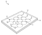
도 1은 미세가공된 초음파 트랜스듀서의 캐비티들에 접근하기 위한 압력 포트들을 포함하는 미세가공된 초음파 트랜스듀서들의 어레이의 사시도이다.
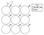
도 2는 도 1의 구조체의 캐비티 층의 개략 평면도이다.
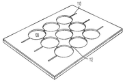
도 3은 캐비티들 및 채널들을 포함하는 도 1의 디바이스의 층을 예시한다.
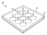
도 4는 각자의 압력 포트들을 갖는 초음파 트랜스듀서들의 어레이를 갖는 도 1의 대안을 예시한다.
도 5는 도 4의 구조체의 캐비티 층의 개략 평면도이다.
도 6은 캐비티들 및 압력 포트들의 부분들을 포함하는 도 4의 캐비티 층을 예시한다.
도 7은 초음파 트랜스듀서당 2개의 압력 포트를 포함하는 초음파 트랜스듀서들 및 압력 포트들의 대안의 어레이를 예시한다.
도 8은 초음파 트랜스듀서당 2개의 압력 포트를 포함하는 초음파 트랜스듀서들 및 압력 포트들의 대안의 어레이를 예시한다.
도 9는 초음파 트랜스듀서들 사이에 압력 포트들이 공유되는 초음파 트랜스듀서들 및 압력 포트들의 대안의 어레이를 예시한다.
도 10은 도 9의 디바이스에서 사용될 수 있는 유형의 압력 포트의 단면도이다.
도 11은 압력 포트를 갖는 미세가공된 초음파 트랜스듀서의 비제한적인 예의 단면도이다.
도 12는 일부 실시예에 따른, 압력 포트를 갖는 초음파 트랜스듀서를 형성하기 위한 제조 프로세스의 플로차트이다.Various aspects and embodiments of the present application will be described with reference to the following drawings. It should be understood that the drawings are not necessarily drawn to scale. Items appearing in multiple figures are denoted by the same reference numerals in all figures in which they appear.
1 is a perspective view of an array of micromachined ultrasonic transducers including pressure ports for accessing cavities of the micromachined ultrasonic transducer.
2 is a schematic plan view of a cavity layer of the structure of FIG. 1;
3 illustrates a layer of the device of FIG. 1 comprising cavities and channels.
4 illustrates the alternative of FIG. 1 with an array of ultrasonic transducers with respective pressure ports.
5 is a schematic plan view of a cavity layer of the structure of FIG. 4;
6 illustrates the cavity layer of FIG. 4 including portions of cavities and pressure ports.
7 illustrates an alternative array of ultrasonic transducers and pressure ports comprising two pressure ports per ultrasonic transducer.
8 illustrates an alternative array of pressure ports and ultrasonic transducers comprising two pressure ports per ultrasonic transducer.
9 illustrates an alternative array of ultrasonic transducers and pressure ports in which pressure ports are shared between the ultrasonic transducers.
10 is a cross-sectional view of a pressure port of the type that may be used in the device of FIG. 9;
11 is a cross-sectional view of a non-limiting example of a microfabricated ultrasonic transducer having a pressure port.
12 is a flow chart of a manufacturing process for forming an ultrasonic transducer having a pressure port, in accordance with some embodiments.
본 출원의 양태는 압력 포트를 포함하는 미세가공된 초음파 트랜스듀서(MUT)를 제공한다. MUT는, 예를 들어, 상부 측면과 하부 측면이, 제각기, 멤브레인과 기판에 의해 밀봉되는, 밀봉된 캐비티를 포함할 수 있다. 압력 포트는 밀봉된 캐비티에 대한 접근 구멍을 나타낼 수 있다. 압력 포트는 MUT의 제조 동안 밀봉된 캐비티 내의 압력을 제어하는 기능을 할 수 있다. 일단 캐비티 또는 캐비티들의 압력이 원하는대로 설정되면, 압력 포트가 밀봉될 수 있다.An aspect of the present application provides a micromachined ultrasonic transducer (MUT) comprising a pressure port. The MUT may comprise a sealed cavity, for example, the upper side and the lower side being sealed by a membrane and a substrate, respectively. The pressure port can represent an access hole to the sealed cavity. The pressure port can function to control the pressure in the sealed cavity during manufacture of the MUT. Once the cavity or the pressure of the cavities is set as desired, the pressure port can be sealed.
MUT를 위한 압력 포트를 포함시키는 것은 다양한 이점을 제공할 수 있다. 압력 포트는 MUT의 밀봉된 캐비티의 압력을 제어할 수 있게 한다. 일부 초음파 디바이스는 수백, 수천, 또는 수십만 개의 MUT와 같은, 많은 수의 MUT를 포함한다. 그러한 초음파 디바이스의 동작은 MUT의 영역에 걸쳐 실질적으로 동일하거나 균일한 압력을 갖는 것으로부터 (예를 들면, 댐핑을 최소화함으로써) 정확도 및 다이내믹 레인지 면에서 이득을 볼 수 있다. 따라서, 초음파 디바이스의 개별 MUT 또는 MUT 서브그룹을 위한 압력 포트들을 제공하는 것은 감지 영역에 걸쳐 더 균일한 압력을 달성하는 것을 용이하게 할 수 있다. 압력 포트들은 다수의 MUT를 포함하는 감지 영역에 걸쳐 캐비티 압력의 균등화를 가능하게 할 수 있다. 압력 포트들은 제조 동안 사용될 수 있으며, 캐비티들이 압력 면에서 균등화된 후에 밀봉된다.Including a pressure port for the MUT can provide a variety of advantages. The pressure port makes it possible to control the pressure in the sealed cavity of the MUT. Some ultrasound devices contain a large number of MUTs, such as hundreds, thousands, or hundreds of thousands of MUTs. The operation of such an ultrasonic device can benefit in terms of accuracy and dynamic range (eg, by minimizing damping) from having substantially the same or uniform pressure across the area of the MUT. Thus, providing pressure ports for individual MUTs or MUT subgroups of an ultrasonic device can facilitate achieving a more uniform pressure across the sensing area. The pressure ports may enable equalization of cavity pressure across a sensing area containing multiple MUTs. The pressure ports can be used during manufacture, and the cavities are sealed in pressure after equalization.
초음파 트랜스듀서 압력 포트들의 다양한 특성들이 본 출원의 양태에 따라 선택될 수 있다. 일부 양태에 따르면, 각각의 초음파 트랜스듀서는 하나 이상의 각자의 압력 포트를 가질 수 있다. 대안의 양태에 따르면, 압력 포트는 2개 이상의 초음파 트랜스듀서에 의해 공유될 수 있다. 본 출원의 양태에 따르면, 초음파 트랜스듀서들의 어레이는 어레이에 대해 서로 동일한 각도로 배향된 각자의 압력 포트들을 포함할 수 있다. 대안의 양태에 따르면, 초음파 트랜스듀서들의 어레이는 각자의 압력 포트들을 포함할 수 있으며, 여기서 2개 이상의 압력 포트가 어레이에 대해 상이한 각도들로 배향된다. 초음파 트랜스듀서들의 어레이에 제공되는 압력 포트들의 개수는 초음파 트랜스듀서들의 개수보다 더 적거나, 동일하거나, 또는 더 클 수 있다. 추가 변형들이 가능하다.Various properties of the ultrasonic transducer pressure ports can be selected according to aspects of the present application. According to some aspects, each ultrasonic transducer may have one or more respective pressure ports. According to an alternative aspect, the pressure port may be shared by two or more ultrasonic transducers. According to an aspect of the present application, an array of ultrasonic transducers may include respective pressure ports oriented at the same angle with respect to the array. According to an alternative aspect, the array of ultrasonic transducers may include respective pressure ports, wherein two or more pressure ports are oriented at different angles with respect to the array. The number of pressure ports provided to the array of ultrasonic transducers may be less, the same, or greater than the number of ultrasonic transducers. Additional variations are possible.
위에서 설명된 양태 및 실시예는 물론, 추가 양태 및 실시예가 아래에서 추가로 설명된다. 이러한 양태 및/또는 실시예는 개별적으로, 모두 함께, 또는 둘 이상의 임의의 조합으로 사용될 수 있는데, 그 이유는 본 출원이 이 점에서 제한되지 않기 때문이다.The aspects and embodiments described above, as well as additional aspects and embodiments, are further described below. These aspects and/or embodiments may be used individually, all together, or in any combination of two or more, since the present application is not limited in this regard.
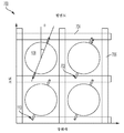
본 출원의 일 양태에 따르면, 초음파 트랜스듀서들의 어레이를 위한 압력 포트들이 제공된다. 일부 실시예에서, 초음파 트랜스듀서들은 상호연결 채널에 의해 서로 연결되는 밀봉된 캐비티들을 포함하고, 복수의 압력 포트들은 초음파 트랜스듀서들의 어레이에 의해 공유된다. 도 1은 비제한적인 예이고, 미세가공된 초음파 트랜스듀서의 캐비티들에 접근하기 위한 압력 포트들을 포함하는 미세가공된 초음파 트랜스듀서들의 어레이의 사시도이다. 초음파 디바이스(100)는 멤브레인(104), 절연 층(106) 및 캐비티들(108)에 의해 형성된 9개의 MUT(102)의 어레이를 포함한다. 압력 포트들(110)이 제공되고, 채널들(112)은 캐비티들(108)을 상호연결시킨다. 일부 실시예에서, 절연 층(106)은 상보형 금속 산화물 반도체(CMOS) 웨이퍼의 일부일 수 있고, 캐비티들(108)은 CMOS 웨이퍼의 절연 층(106)에 형성될 수 있다.According to an aspect of the present application, pressure ports are provided for an array of ultrasonic transducers. In some embodiments, the ultrasonic transducers include sealed cavities that are connected to each other by an interconnection channel, and a plurality of pressure ports are shared by an array of ultrasonic transducers. 1 is a non-limiting example, and is a perspective view of an array of micromachined ultrasonic transducers including pressure ports for accessing cavities of the micromachined ultrasonic transducer. The
압력 포트들(110)은 임의의 적합한 위치를 가질 수 있다. 예시된 비제한적인 예에서, 이들은 어레이의 주변부에 배치되고, 이 비제한적인 예에서, 어레이의 주변부의 2개의 대향 측면에 배치된다. 압력 포트들이, 도시된 바와 같이, 어레이의 주변부에 배치될 때, 어레이 내부의 캐비티들의 캐비티 압력에 대한 제어는, 공기 채널일 수 있는, 채널들(112)의 존재로 인해 여전히 달성될 수 있다. 그렇지만, 대안의 구성들이 가능하다. 예를 들어, 다른 실시예에서 도시된 바와 같이 각각의 개별 캐비티에 대해 압력 포트가 제공될 수 있다. 대안적으로, 도시된 것보다 더 적은 압력 포트들이 제공될 수 있으며, 어레이에 걸쳐 캐비티 압력의 제어를 가능하게 하기 위해 추가 채널들(112)이 제공된다.
배치 및 크기를 포함한, 압력 포트들(110)의 다양한 특성들이 언급될 수 있다. 도시된 비제한적인 예에서, 압력 포트들(110)은 어레이의 2개의 대향 측면에 배치된다. 이 비제한적인 예에서, 2개의 압력 포트는 주어진 열에 있는 초음파 트랜스듀서들을 양분하는 라인에 배치된다. 그렇지만, 압력 포트들의 대안의 배치가 가능하다. 압력 포트들은 임의의 적합한 치수를 가질 수 있고, 임의의 적합한 방식으로 형성될 수 있다. 일부 실시예에서, 압력 포트들은 초음파 트랜스듀서들의 성능에 부정적인 영향을 미치지 않도록 충분히 작다. 또한, 일단 캐비티들(108)의 압력이 원하는 값으로 설정되면 압력 포트들이 밀봉될 수 있도록 압력 포트들은 충분히 작을 수 있다. 예를 들어, 압력 포트들은 대략 0.1 미크론 내지 20 미크론 - 해당 범위 내의 임의의 값 또는 값 범위를 포함함 - 의 직경을 가질 수 있다. 압력 포트들은 임의의 적합한 방식으로, 예컨대, 금속 재료로 밀봉될 수 있다. 예를 들어, 압력 포트들을 밀봉하기 위해 알루미늄이 스퍼터링될 수 있다.Various characteristics of the
압력 포트들은 MUT(들)의 제조 동안 생성되어 사용될 수 있다. 일부 실시예에서, 밀봉된 캐비티들은 웨이퍼 본딩 기술을 사용하여 형성될 수 있다. 웨이퍼 본딩 기술은 웨이퍼 또는 MUT들의 어레이에 걸쳐 균일한 캐비티 압력을 달성하는 데 부적절할 수 있다. 또한, 웨이퍼 본딩을 위해 존재하는 화학 물질들이 MUT들의 어레이의 특정 캐비티들을 불균등하게 점유하거나 그에 남아 있을 수 있다. 캐비티들이 (예를 들어, 웨이퍼 본딩에 의해) 밀봉된 후에, 압력 포트들이 개방될 수 있다. 밀봉된 캐비티들의 압력들은 이어서 웨이퍼를 원하는 제어된 압력에 노출시킴으로써 균등화될 수 있거나 또는 실질적으로 동일하게 될 수 있다. 또한, 원하는 화학 물질들(예를 들면, 아르곤)이 압력 포트들을 통해 캐비티들에 유입될 수 있다. 후속하여, 압력 포트들이 밀봉될 수 있다.Pressure ports can be created and used during manufacture of the MUT(s). In some embodiments, sealed cavities may be formed using wafer bonding techniques. Wafer bonding techniques may be inadequate to achieve uniform cavity pressure across a wafer or array of MUTs. In addition, chemicals present for wafer bonding may unevenly occupy or remain in certain cavities of the array of MUTs. After the cavities are sealed (eg, by wafer bonding), the pressure ports can be opened. The pressures of the sealed cavities can then be equalized or made substantially the same by exposing the wafer to a desired controlled pressure. In addition, desired chemicals (eg, argon) can enter the cavities through the pressure ports. Subsequently, the pressure ports can be sealed.
따라서, 본 발명자들은 복수의 MUT들의 밀봉된 캐비티들의 압력 및/또는 화학적 함량의 제어가 압력 포트를 사용하여 개선될 수 있음을 인식하였다. 압력 포트는 밀봉된 캐비티들을 형성하는 데 사용되는 웨이퍼 본딩 프로세스보다 이러한 파라미터들에 대한 더 큰 제어를 제공할 수 있다.Thus, the inventors have recognized that the control of the pressure and/or chemical content of the sealed cavities of a plurality of MUTs can be improved using a pressure port. The pressure port can provide greater control over these parameters than the wafer bonding process used to form the sealed cavities.
도 2는 도 1의 초음파 디바이스(100)의 캐비티 층의 평면도를 예시한다. 도시된 바와 같이, 채널들(112)에 의해 상호연결된 9개의 캐비티가 포함된다. 다시 말하지만, 채널들(112)은 인접한 캐비티들에서의 압력이 균일한 레벨로 설정될 수 있게 하는 공기 채널들일 수 있다. 채널들(112)은 0.1 미크론 내지 20 미크론 - 해당 범위 내의 임의의 값 또는 값 범위를 포함함 - 과 같은, 이러한 목적에 적합한 임의의 치수를 가질 수 있다.2 illustrates a top view of the cavity layer of the
도 1 및 도 2의 초음파 디바이스는 비제한적인 예이다. 도시된 미세가공된 초음파 트랜스듀서들의 개수, 형상, 치수, 및 배치는 모두 변수들이다. 예를 들어, 도 2는 원형 캐비티들을 예시하지만, 다각형, 정사각형, 또는 임의의 다른 적합한 형상과 같은, 다른 형상들이 가능하다. 도시된 압력 포트들의 배치 및 개수가 또한 특정 애플리케이션에 대해 선택될 수 있다.The ultrasound device of FIGS. 1 and 2 is a non-limiting example. The number, shape, dimensions, and arrangement of the microfabricated ultrasonic transducers shown are all variables. For example, while FIG. 2 illustrates circular cavities, other shapes are possible, such as polygonal, square, or any other suitable shape. The arrangement and number of pressure ports shown can also be selected for a particular application.
도 3은 캐비티들 및 채널들을 포함하는 도 1의 디바이스의 캐비티 층의 사시도를 예시한다. 이 도면에서, 초음파 디바이스(100)의 멤브레인 층은 생략되어 있다. 캐비티들(108), 채널들(112), 및 압력 포트들(110)의 일부는, 예를 들어, 에칭에 의해 형성될 수 있다. 후속하여, 멤브레인(104)은 멤브레인 층을 생성함으로써 캐비티들(108)을 밀봉하도록 형성될 수 있다. 압력 포트들(110)의 수직 부분은 이어서 멤브레인(104)을 통해 에칭되어 초음파 디바이스(100)를 형성할 수 있다.3 illustrates a perspective view of the cavity layer of the device of FIG. 1 including cavities and channels. In this figure, the membrane layer of the
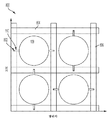
이전에 설명된 바와 같이, 초음파 트랜스듀서들의 어레이에 제공되는 압력 포트들의 개수 및 배치는 도 1에 도시된 것과 상이할 수 있다. 본 출원의 양태에 따르면, 초음파 트랜스듀서들의 어레이는 각자의 압력 포트들을 갖는 캐비티들의 어레이를 포함한다. 도 4는 도 1의 대안을 나타내고 각자의 압력 포트들을 갖는 초음파 트랜스듀서들의 어레이를 갖는 예를 예시한다. 초음파 디바이스(400)는 캐비티들(108), 멤브레인(104), 및 절연 층(106)을 포함한다. 이 비제한적인 실시예에서 각각의 캐비티(108)에 대해 하나의 압력 포트가 제공된다. 추가적으로, 캐비티들이 채널들(112)에 의해 상호연결되지 않는다. 또한, 이 비제한적인 예에서, 압력 포트들 모두가 캐비티들에 대해 공통 각도로 배향되고 모두가 캐비티 어레이의 주변에 배치되지는 않음을 알 수 있다.As previously described, the number and arrangement of pressure ports provided in the array of ultrasonic transducers may be different from that shown in FIG. 1. In accordance with an aspect of the present application, an array of ultrasonic transducers comprises an array of cavities having respective pressure ports. 4 shows an alternative to FIG. 1 and illustrates an example with an array of ultrasonic transducers with respective pressure ports. The
도 5는 도 4의 구조체의 캐비티 층의 개략 평면도이다. 도시된 바와 같이, 캐비티들(108)은 캐비티들과 평면 내에 있는 부분 및 캐비티들에 수직인 부분(캐비티들과 평면 내에 있는 부분의 단부에 있는 원으로 표현됨) 둘 모두를 포함하는 압력 포트들(110)을 포함한다.5 is a schematic plan view of a cavity layer of the structure of FIG. 4; As shown, the
도 6은 캐비티들(108) 및 압력 포트들(110)을 포함하는 도 4의 캐비티 층을 예시한다. 이 뷰에서, 캐비티들과 평면 내에 있는 압력 포트들의 부분이 예시되어 있다. 캐비티들(108)에 수직으로 위쪽으로 연장되는 압력 포트들의 부분이 도 6의 일부가 아닌 멤브레인(104)을 통해 연장되기 때문에, 해당 부분은 도시되지 않는다. 캐비티들(108) 및 캐비티들(108)과 평면 내에 있는 압력 포트들(110)의 부분들은 임의의 적합한 방식으로 형성될 수 있다. 예를 들어, 절연 층(106)을 에칭하기 위한 임의의 적합한 기술이 캐비티들(108) 및 압력 포트들(110)의 평면내 부분들을 형성하는 데 사용될 수 있다. 도 4의 초음파 디바이스(400)는 멤브레인(104)을 형성하고 압력 포트들(110)의 수직 부분들을 에칭함으로써 도 6의 구조체로부터 형성될 수 있다.6 illustrates the cavity layer of FIG. 4 including
이전에 설명된 바와 같이, 초음파 트랜스듀서들의 어레이에 대해 압력 포트들의 다양한 구성들이 사용될 수 있다. 도 1 및 도 4는 2개의 비제한적인 예를 예시한다. 도 7은 추가 대안을 예시한다. 도 7의 비제한적인 예에서, 각각의 캐비티에 대해 2개의 압력 포트가 제공된다. 캐비티당 하나 초과의 압력 포트를 제공하는 것은, 물 또는 다른 요소들과 같은, 바람직하지 않은 요소들을 캐비티로부터 제거하는 것을 더 쉽도록 만들 수 있다. 캐비티당 하나 초과의 포트를 갖는 것은 또한 캐비티에 대한 원하는 압력을 달성하는 것을 용이하게 할 수 있다. 초음파 디바이스(700)에서, 압력 포트들은, 단부에 개구부들(702)을 갖는, 채널들 또는 연장부들에 의해 표현된다. 압력 포트들(110)이 고도 방향에 대해 각도 θ로 배향되어 있음을 알 수 있다. 해당 각도는 5도 내지 40도, 또는 임의의 다른 적합한 수일 수 있다. 금속 라인들(704 및 706)이 또한 도 7에 도시되어 있다. 금속 라인들(704)은 방위각 방향으로 뻗어 있는 반면, 금속 라인들(706)은 고도 방향으로 뻗어 있다. 금속 라인들(704 및 706)은 초음파 트랜스듀서들로/로부터 신호들을 제공하기 위한 전도성 트레이스들을 나타낼 수 있다. 일부 실시예에서, 모든 압력 포트들이 방위각 또는 고도 방향으로만 배향된 금속 라인들에서 종단되도록 하는 것이 바람직할 수 있으며, 따라서 압력 포트들을 각도 θ로 경사지게 하는 것은 그러한 구성을 용이하게 할 수 있다. 예를 들어, 도시된 바와 같이, 도 7에서의 모든 압력 포트들은 방위각 방향으로 배향된 금속 라인들에서 종단된다. 금속 라인들의 금속은 압력 포트들의 단부들을 밀봉할 수 있다. 예를 들어, 금속 라인들을 형성하기 위해 알루미늄을 스퍼터링하는 것은 압력 포트들을 밀봉할 수 있다.As previously described, various configurations of pressure ports can be used for an array of ultrasonic transducers. 1 and 4 illustrate two non-limiting examples. 7 illustrates a further alternative. In the non-limiting example of FIG. 7, two pressure ports are provided for each cavity. Providing more than one pressure port per cavity can make it easier to remove undesirable elements from the cavity, such as water or other elements. Having more than one port per cavity can also facilitate achieving the desired pressure on the cavity. In the
도 8은 초음파 트랜스듀서당 2개의 압력 포트를 포함하는 초음파 트랜스듀서들 및 압력 포트들의 대안의 어레이를 예시한다. 예시된 초음파 디바이스(800)는 이웃하는 캐비티들에 대한 압력 포트들이 서로 상이하게 배향된다는 점에서 도 7의 것과 상이하다. 이 예에서, 주어진 캐비티에 대한 압력 포트들이 방위각 방향을 따라 배향될 때, 바로 이웃한 캐비티들에 대한 압력 포트들은 고도 방향을 따라 배향되고, 그 반대의 경우도 마찬가지이다.8 illustrates an alternative array of pressure ports and ultrasonic transducers comprising two pressure ports per ultrasonic transducer. The illustrated
도 9는 초음파 트랜스듀서들 사이에 압력 포트들이 공유되는 초음파 트랜스듀서들 및 압력 포트들의 대안의 어레이를 예시한다. 초음파 디바이스(900)는 캐비티들(108), 금속 라인들(904 및 906), 채널들(110) 및 접근 구멍들(902)을 포함한다. 압력 포트들은 채널들(110)과 접근 구멍들(902)의 조합을 나타낼 수 있다. 접근 구멍들은, 개구부들(902)로서 도 9에 도시된 바와 같이, 수직으로, 예를 들어, 캐비티들(108)에 수직으로 연장될 수 있다. 채널들(110)은 도시된 바와 같이 이웃하는 캐비티들(108)을 상호연결시킬 수 있다. 이 예에서, 동일한 수의 압력 포트들 및 캐비티들이 제공되고 압력 포트들은 어레이의 주변부에 배치되지 않고 어레이 내부에서 접근 가능하다.9 illustrates an alternative array of ultrasonic transducers and pressure ports in which pressure ports are shared between the ultrasonic transducers. The
도 10은 도 9의 디바이스에서 사용될 수 있는 유형의 압력 포트의 단면도(10)이다. 압력 포트는 폭 X1을 갖는 902로 표현된 수직 부분과, 폭 X2를 갖는 평면내 부분 또는 채널을 포함한다. X1의 값은 초음파 트랜스듀서의 동작에 부정적인 영향을 미치지 않도록, 그리고 또한 용이한 충전(filling)을 가능하게 하기 위해 충분히 작도록 선택될 수 있다. 일부 실시예에서, X1은, 0.1 미크론 내지 20 미크론과 같은, 압력 포트 및 접근 구멍 치수와 관련하여 본 명세서에서 이전에 설명된 값 중 임의의 것을 취할 수 있다. X2의 값도 마찬가지로 임의의 그러한 값을 취할 수 있다. 예시된 예에서, X1은 X2보다 작다.10 is a cross-sectional view 10 of a pressure port of the type that may be used in the device of FIG. 9. The pressure port includes a vertical portion represented by 902 having a width X1 and an in-plane portion or channel having a width X2. The value of X1 can be chosen to be small enough so as not to negatively affect the operation of the ultrasonic transducer, and also to allow easy filling. In some embodiments, X1 may take any of the values previously described herein with respect to pressure port and access hole dimensions, such as 0.1 microns to 20 microns. The value of X2 can likewise take any such value. In the illustrated example, X1 is less than X2.
일부 실시예에서, 멤브레인(104)은 상이한 재료 조성들을 갖는 하나 이상의 층으로 형성될 수 있다. 멤브레인(104)은 SOI(silicon on insulator) 웨이퍼로 형성될 수 있다. SOI 웨이퍼는 매립 산화물(BOX) 층(104a), 단결정 층(104b), 및 열 산화물 층(104c)을 포함하지만 이에 제한되지 않는 여러 층을 포함할 수 있다. SOI 웨이퍼는 화학적 기계적 폴리싱(CMP)과 같은 임의의 적합한 기술에 의해 웨이퍼 본딩 이후에 제거되는 핸들링 웨이퍼(handling wafer)를 추가로 포함할 수 있다. BOX 층(104a)은, 0.5 내지 2 미크론 두께 또는 임의의 다른 적합한 값과 같은, 임의의 적합한 두께일 수 있다. 단결정 층(104b)은 단결정 Si 또는 임의의 적합한 단결정 재료일 수 있다. 단결정 층(104b)은 또한, 4 내지 10 미크론 두께를 포함하여, MUT들의 동작을 가능하게 하는 임의의 적합한 두께일 수 있다. 열 산화물 층(104c)은, 100 내지 300 nm 두께와 같은, 임의의 적합한 두께일 수 있다.In some embodiments,
도 11은 캐비티(108) 및 압력 포트(110)를 갖는 MUT(1100)의 비제한적인 예의 단면도이다. 도시된 바와 같이, 압력 포트는 밀봉될 수 있으며, 따라서 예시된 디바이스는 캐비티 압력이 원하는 값으로 설정된 후의 디바이스의 상태를 나타낼 수 있다. 그 시점에서, 압력 포트는 시간의 함수로서 밀봉된 캐비티 내의 실질적으로 일정한 압력을 제공하기 위해 밀봉부(1102)로 밀봉될 수 있다.11 is a cross-sectional view of a non-limiting example of a
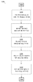
MUT(1100)와 같은 MUT의 제조 프로세스는 도 12의 프로세스(1200)에 의해 설명된다. 먼저, 동작(1202)에서, 캐비티들(108), 압력 포트들(110), 및/또는 채널들(112)과 같은, 그러나 이에 제한되지 않는 피처들이 절연 층(106)에 형성된다. 캐비티들(108), 압력 포트들(110), 및/또는 채널(112)은 반응성 이온 에칭(RIE), 깊은 반응성 이온 에칭(DRIE), 이온 밀링, 플라즈마 에칭, 또는 임의의 다른 적절한 방법을 포함하는 임의의 적절한 에칭 프로세스에 의해 형성될 수 있다. 절연 층(106)은 캐비티들이 CMOS 웨이퍼의 다른 요소들에 전기적으로 결합되도록 더 큰 CMOS 웨이퍼의 일부일 수 있다.The manufacturing process of a MUT, such as
동작(1204)에서, 피처들을 갖는 절연 층(106)은 이전에 논의된 유형의 SOI 웨이퍼일 수 있는 멤브레인 웨이퍼에 웨이퍼 본딩될 수 있다. 웨이퍼 본딩 프로세스는 저온 웨이퍼 본딩 프로세스일 수 있다. 웨이퍼 본딩 프로세스는 포스트 프로세스(post-process) 어닐링 단계를 또한 포함할 수 있다. 어닐링 동안, 캐비티들(108) 내부의 압력을 제어하는 것을 돕기 위해 게터링(gettering) 재료들이 존재할 수 있다. 예를 들어, 게터링 재료들은 Ti, TiN, SrO, 및/또는 Zr-Al을 포함할 수 있다. 동작(1206)에서, 멤브레인 웨이퍼의 핸들링 웨이퍼가 연마될 수 있어, 캐비티들(108) 위의 멤브레인(104)이 굴곡될 수 있게 한다. 핸들링 웨이퍼는 화학적 기계적 폴리싱을 포함한 임의의 적합한 방식으로 연마될 수 있다.In
동작(1208)에서, 개구부들(902)과 같은 개구부들이 형성되어 압력 포트들(110)을 개방시켜, 캐비티들(108)의 압력이 균등화될 수 있게 한다. 개구부들은 RIE 및/또는 DRIE와 같은 임의의 적합한 에칭 프로세스를 사용하여 형성될 수 있다. 일부 실시예에서, RIE는 먼저 BOX 층(104a)을 통해 에칭하는 데 사용된다. 이어서, DRIE는 단결정 층(104b)을 에칭하는 데 사용되며, RIE는 열 산화물 층(104c)을 통해 에칭하는 데 또다시 사용된다. 압력 포트들(110)이 진공 하에서 개방되기 때문에, 웨이퍼 본딩 및/또는 어닐링 프로세스로부터의 임의의 아웃개싱된 재료들이 동작(1208) 동안 빠져나가고, 캐비티들(108)의 압력은 진공 챔버의 압력과 균등화된다.In
동작(1210)에서, 캐비티들(108)이 동작에 적합한 압력으로 유지될 수 있도록 압력 포트들(110)이 밀봉된다. 압력 포트들(110)은 임의의 적합한 재료에 의해 또는 스퍼터링 프로세스와 같은, 그러나 이에 제한되지 않는 임의의 적합한 프로세스에 의해 밀봉될 수 있다. 압력 포트들(110)은 다수의 재료들로 형성된 다층 구조체에 의해 밀봉될 수 있다. 예시적인 재료들은 Al, Cu, Al/Cu 합금들, 및 TiN을 임의의 적합한 조합으로 포함한다.In
본 명세서에서 설명된 미세가공된 초음파 트랜스듀서들은 다양한 유형들일 수 있다. 일부 실시예에서, 이들은 용량성 미세가공된 초음파 트랜스듀서(CMUT)일 수 있다. 그러한 상황에서, 이들은 웨이퍼 본딩 또는 희생 방출(sacrificial release) 방법에 의해 형성될 수 있다. 일부 실시예에서, 미세가공된 초음파 트랜스듀서들은 압전 미세가공된 초음파 트랜스듀서(PMUT)이다.The microfabricated ultrasonic transducers described herein can be of various types. In some embodiments, these may be capacitive microfabricated ultrasonic transducers (CMUTs). In such situations, they can be formed by wafer bonding or sacrificial release methods. In some embodiments, the micromachined ultrasonic transducers are piezoelectric micromachined ultrasonic transducers (PMUT).
다양한 유형의 초음파 디바이스들은 본 명세서에서 설명된 유형들의 압력 포트들을 갖는 MUT들을 구현할 수 있다. 일부 실시예에서, 핸드헬드 초음파 프로브는 압력 포트들을 갖는 MUT들을 포함하는 초음파 온 칩(ultrasound-on-a-chip)을 포함할 수 있다. 일부 실시예에서, 초음파 패치가 이 기술을 구현할 수 있다. 정제(pill)가 또한 이 기술을 활용할 수 있다. 따라서, 본 출원의 양태는 압력 포트들을 갖는 MUT들을 포함하는 그러한 초음파 디바이스들을 제공한다.Various types of ultrasonic devices can implement MUTs with pressure ports of the types described herein. In some embodiments, the handheld ultrasound probe may include an ultrasound-on-a-chip including MUTs with pressure ports. In some embodiments, an ultrasonic patch may implement this technique. Pills can also utilize this technique. Accordingly, an aspect of the present application provides such ultrasonic devices including MUTs with pressure ports.
따라서 본 출원의 기술의 여러 양태 및 실시예를 설명하였지만, 다양한 변경들, 수정들, 및 개선들이 본 기술 분야의 통상의 기술자에게 용이하게 안출될 것임이 이해되어야 한다. 그러한 변경들, 수정들, 및 개선들은 본 출원에서 설명된 기술의 사상 및 범위 내에 있는 것으로 의도된다. 따라서, 전술한 실시예들이 단지 예로서 제시되어 있다는 것과, 첨부된 청구항들 및 그의 균등물들의 범위 내에서, 발명 실시예들이 구체적으로 설명된 것과 다른 방식으로 실시될 수 있다는 것이 이해되어야 한다.Accordingly, although various aspects and embodiments of the technology of the present application have been described, it should be understood that various changes, modifications, and improvements will be readily made to those skilled in the art. Such changes, modifications, and improvements are intended to be within the spirit and scope of the technology described in this application. Accordingly, it should be understood that the foregoing embodiments have been presented by way of example only, and that, within the scope of the appended claims and their equivalents, the inventive embodiments may be practiced in a manner other than that specifically described.
설명된 바와 같이, 일부 양태는 하나 이상의 방법으로서 구현될 수 있다. 이 방법(들)의 일부로서 수행되는 동작들은 임의의 적당한 방식으로 정렬될 수 있다. 그에 따라, 동작들이 예시된 것과 상이한 순서로 수행되는 실시예들이 구성될 수 있으며, 이 실시예들은 일부 동작들을, 비록 예시적인 실시예들에서 순차적인 동작들로서 도시되어 있더라도, 동시에 수행하는 것을 포함할 수 있다.As described, some aspects can be implemented as one or more methods. The operations performed as part of this method(s) may be arranged in any suitable manner. Accordingly, embodiments in which the operations are performed in a different order than those illustrated may be constructed, and these embodiments include performing some operations simultaneously, even though they are shown as sequential operations in the exemplary embodiments. I can.
본 명세서에서 정의되고 사용되는 바와 같은, 모든 정의들은 사전 정의(dictionary definition), 참고로 포함된 문서들에서의 정의, 및/또는 정의된 용어들의 통상적인 의미보다 우선하는 것으로 이해되어야 한다.All definitions, as defined and used herein, are to be understood as taking precedence over dictionary definitions, definitions in documents incorporated by reference, and/or the usual meaning of the defined terms.
문구 "및/또는"은, 명세서에서 그리고 청구범위에서 본 명세서에 사용되는 바와 같이, 그와 같이 등위 접속된(conjoined) 요소들, 즉 일부 경우에서 결합적으로(conjunctively) 존재하고 다른 경우에서 택일적으로(disjunctively) 존재하는 요소들 중 "어느 하나 또는 둘 다"를 의미하는 것으로 이해되어야 한다.The phrase “and/or”, as used herein in the specification and in the claims, is conjoined elements as such, ie, in some cases conjunctively present and alternative in others. It is to be understood as meaning "either or both" of the elements that are disjunctively present.
본 명세서에서 명세서에 그리고 청구범위에 사용되는 바와 같이, 하나 이상의 요소의 목록에 대한 언급에서의 문구 "적어도 하나"는 요소들의 목록 내의 요소들 중 임의의 하나 이상의 요소 중에서 선택된 적어도 하나의 요소를 의미하는 것으로 이해되어야 하지만, 요소들의 목록 내에 구체적으로 열거된 각기의 요소 중 적어도 하나를 반드시 포함하는 것은 아니며 요소들의 목록 내의 요소들의 임의의 조합들을 배제하지 않는다.As used herein in the specification and in the claims, the phrase “at least one” in reference to a list of one or more elements means at least one element selected from any one or more of the elements in the list of elements. It should be understood that the list of elements does not necessarily include at least one of each element specifically listed within the list of elements and does not exclude any combinations of elements within the list of elements.
본 명세서에서 사용되는 바와 같이, 수치 맥락에서 사용된 용어 "내지"는 달리 지시되지 않는 한 포함적(inclusive)인 것이다. 예를 들어, "A 내지 B"는 달리 명시되지 않는 한 A와 B를 포함한다.As used herein, the term “to” as used in a numerical context is inclusive unless otherwise indicated. For example, "A to B" includes A and B unless otherwise specified.
용어 "대략" 및 "약"은 일부 실시예에서 목표 값의 ± 20% 이내, 일부 실시예에서 목표 값의 ± 10% 이내, 일부 실시예에서 목표 값의 ± 5% 이내, 그리고 또한 일부 실시예에서 목표 값의 ± 2% 이내를 의미하기 위해 사용될 수 있다. 용어 "대략" 및 "약"은 목표 값을 포함할 수 있다.The terms “approximately” and “about” are within ± 20% of the target value in some embodiments, within ± 10% of the target value in some embodiments, within ± 5% of the target value in some embodiments, and also in some embodiments. Can be used to mean within ± 2% of the target value in The terms “approximately” and “about” may include target values.
Claims (20)
기판 및 멤브레인을 포함하는 초음파 트랜스듀서 - 상기 기판 및 상기 멤브레인은 밀봉된 캐비티가 이들 사이에 있도록 배치됨 -; 및
상기 멤브레인을 관통하고 상기 밀봉된 캐비티에 대한 접근을 제공하도록 구성된 접근 구멍
을 포함하는, 초음파 디바이스.As an ultrasonic device,
An ultrasonic transducer comprising a substrate and a membrane, the substrate and the membrane arranged such that a sealed cavity is between them; And
An access hole configured to penetrate the membrane and provide access to the sealed cavity
Containing, ultrasound device.
밀봉된 캐비티; 및
상기 밀봉된 캐비티의 압력을 제어하도록 구성된 압력 포트
를 포함하는, 미세가공된 초음파 트랜스듀서.As a micro-machined ultrasonic transducer,
Sealed cavity; And
Pressure port configured to control the pressure in the sealed cavity
Containing, micro-machined ultrasonic transducer.
The micro-machined ultrasonic transducer of claim 13, wherein the micro-machined ultrasonic transducer is disposed on a handheld ultrasonic probe.
Applications Claiming Priority (5)
| Application Number | Priority Date | Filing Date | Title |
|---|---|---|---|
| US201862666556P | 2018-05-03 | 2018-05-03 | |
| US62/666,556 | 2018-05-03 | ||
| US201862696305P | 2018-07-10 | 2018-07-10 | |
| US62/696,305 | 2018-07-10 | ||
| PCT/US2019/030388 WO2019213388A1 (en) | 2018-05-03 | 2019-05-02 | Pressure port for ultrasonic transducer on cmos sensor |
Publications (1)
| Publication Number | Publication Date |
|---|---|
| KR20210005208A true KR20210005208A (en) | 2021-01-13 |
Family
ID=68384340
Family Applications (1)
| Application Number | Title | Priority Date | Filing Date |
|---|---|---|---|
| KR1020207034403A KR20210005208A (en) | 2018-05-03 | 2019-05-02 | Pressure port for ultrasonic transducer on CMOS sensor |
Country Status (9)
| Country | Link |
|---|---|
| US (1) | US20190336099A1 (en) |
| EP (1) | EP3788798B1 (en) |
| JP (1) | JP2021522734A (en) |
| KR (1) | KR20210005208A (en) |
| CN (1) | CN112075090B (en) |
| AU (1) | AU2019263404A1 (en) |
| CA (1) | CA3098911A1 (en) |
| TW (1) | TW202000137A (en) |
| WO (1) | WO2019213388A1 (en) |
Families Citing this family (13)
| Publication number | Priority date | Publication date | Assignee | Title |
|---|---|---|---|---|
| EP3233311B1 (en) * | 2014-12-21 | 2021-12-08 | Chirp Microsystems, Inc. | Piezoelectric micromachined ultrasonic transducers with low stress sensitivity and methods of fabrication |
| WO2020069252A1 (en) | 2018-09-28 | 2020-04-02 | Butterfly Network, Inc. | Fabrication techniques and structures for gettering materials in ultrasonic transducer cavities |
| US11638931B2 (en) | 2018-11-13 | 2023-05-02 | Bfly Operations, Inc. | Getter technology for micromachined ultrasonic transducer cavities |
| TW202033959A (en) | 2018-11-15 | 2020-09-16 | 美商蝴蝶網路公司 | Anti-stiction bottom cavity surface for micromachined ultrasonic transducer devices |
| TW202045099A (en) | 2019-02-07 | 2020-12-16 | 美商蝴蝶網路公司 | Bi-layer metal electrode for micromachined ultrasonic transducer devices |
| CN113453807B (en) | 2019-02-25 | 2022-09-20 | 蝴蝶网络有限公司 | Adaptive cavity thickness control for micromachined ultrasonic transducer devices |
| WO2020210470A1 (en) | 2019-04-12 | 2020-10-15 | Butterfly Network, Inc. | Bottom electrode via structures for micromachined ultrasonic transducer devices |
| US11501562B2 (en) | 2019-04-30 | 2022-11-15 | Bfly Operations, Inc. | Ultrasound face scanning and identification apparatuses and methods |
| FR3097091B1 (en) * | 2019-06-07 | 2021-07-23 | Commissariat Energie Atomique | device provided with a plurality of resonators collectively exhibiting an improved quality factor |
| US11684951B2 (en) | 2019-08-08 | 2023-06-27 | Bfly Operations, Inc. | Micromachined ultrasonic transducer devices having truncated circle shaped cavities |
| TWI742603B (en) | 2020-04-09 | 2021-10-11 | 伊諾司生技股份有限公司 | A sensor with a chamber |
| WO2021211822A1 (en) | 2020-04-16 | 2021-10-21 | Bfly Operations, Inc. | Methods and circuitry for built-in self-testing of circuitry and/or transducers in ultrasound devices |
| US20210403321A1 (en) * | 2020-06-30 | 2021-12-30 | Butterfly Network, Inc. | Formation of self-assembled monolayer for ultrasonic transducers |
Family Cites Families (23)
| Publication number | Priority date | Publication date | Assignee | Title |
|---|---|---|---|---|
| JPH01296122A (en) * | 1988-05-24 | 1989-11-29 | Matsushita Electric Ind Co Ltd | Pressure sensor |
| US4996627A (en) * | 1989-01-30 | 1991-02-26 | Dresser Industries, Inc. | High sensitivity miniature pressure transducer |
| US5894452A (en) * | 1994-10-21 | 1999-04-13 | The Board Of Trustees Of The Leland Stanford Junior University | Microfabricated ultrasonic immersion transducer |
| US5982709A (en) * | 1998-03-31 | 1999-11-09 | The Board Of Trustees Of The Leland Stanford Junior University | Acoustic transducers and method of microfabrication |
| US6891711B1 (en) * | 2004-04-08 | 2005-05-10 | Kulite Semiconductor Products, Inc. | Ultra-miniature, high temperature, capacitive inductive pressure transducer |
| WO2005114820A2 (en) * | 2004-05-14 | 2005-12-01 | The University Of Georgia Research Foundation, Inc. | Implantable ultrasonic transducer systems and methods |
| JP4347885B2 (en) * | 2004-06-03 | 2009-10-21 | オリンパス株式会社 | Manufacturing method of capacitive ultrasonic transducer, ultrasonic endoscope apparatus including capacitive ultrasonic transducer manufactured by the manufacturing method, capacitive ultrasonic probe, and capacitive ultrasonic transducer Sonic transducer |
| US8454513B2 (en) * | 2004-12-30 | 2013-06-04 | Stc.Unm | Micro-machined medical devices, methods of fabricating microdevices, and methods of medical diagnosis, imaging, stimulation, and treatment |
| GB0605576D0 (en) * | 2006-03-20 | 2006-04-26 | Oligon Ltd | MEMS device |
| US7616077B1 (en) * | 2007-03-22 | 2009-11-10 | Sandia Corporation | Microelectromechanical resonator and method for fabrication |
| EP2659987A1 (en) * | 2009-03-26 | 2013-11-06 | Norwegian University of Science and Technology (NTNU) | Acoustic backing layer for use in an ultrasound transducer |
| JP5529577B2 (en) * | 2010-02-14 | 2014-06-25 | キヤノン株式会社 | Electromechanical transducer and method for manufacturing the same |
| CA2814123A1 (en) | 2010-10-12 | 2012-04-19 | Micralyne Inc. | Soi-based cmut device with buried electrodes |
| JP5901566B2 (en) * | 2013-04-18 | 2016-04-13 | キヤノン株式会社 | Transducer, transducer manufacturing method, and subject information acquisition apparatus |
| AU2014293274B2 (en) * | 2013-07-23 | 2018-11-01 | Butterfly Network, Inc. | Interconnectable ultrasound transducer probes and related methods and apparatus |
| JP2015103821A (en) * | 2013-11-20 | 2015-06-04 | キヤノン株式会社 | Capacitive transducer and manufacturing method thereof |
| WO2015112452A1 (en) * | 2014-01-24 | 2015-07-30 | The Regents Of The University Of California | Curved piezoelectric transducers |
| TWI661534B (en) * | 2014-04-18 | 2019-06-01 | 美商蝴蝶網路公司 | Ultrasonic transducers in complementary metal oxide semiconductor (cmos) wafers and related apparatus and methods |
| WO2016007250A1 (en) * | 2014-07-08 | 2016-01-14 | Qualcomm Incorporated | Piezoelectric ultrasonic transducer and process |
| US9821340B2 (en) * | 2014-07-28 | 2017-11-21 | Kolo Medical Ltd. | High displacement ultrasonic transducer |
| US10001552B2 (en) | 2014-10-15 | 2018-06-19 | Qualcomm Incorporated | Three-port piezoelectric ultrasonic transducer |
| EP3233311B1 (en) * | 2014-12-21 | 2021-12-08 | Chirp Microsystems, Inc. | Piezoelectric micromachined ultrasonic transducers with low stress sensitivity and methods of fabrication |
| US10497748B2 (en) * | 2015-10-14 | 2019-12-03 | Qualcomm Incorporated | Integrated piezoelectric micromechanical ultrasonic transducer pixel and array |
-
2019
- 2019-05-02 KR KR1020207034403A patent/KR20210005208A/en not_active Application Discontinuation
- 2019-05-02 AU AU2019263404A patent/AU2019263404A1/en not_active Abandoned
- 2019-05-02 WO PCT/US2019/030388 patent/WO2019213388A1/en active Application Filing
- 2019-05-02 JP JP2020560488A patent/JP2021522734A/en active Pending
- 2019-05-02 TW TW108115250A patent/TW202000137A/en unknown
- 2019-05-02 EP EP19795861.4A patent/EP3788798B1/en active Active
- 2019-05-02 CA CA3098911A patent/CA3098911A1/en active Pending
- 2019-05-02 CN CN201980029781.8A patent/CN112075090B/en active Active
- 2019-05-02 US US16/401,870 patent/US20190336099A1/en active Pending
Also Published As
| Publication number | Publication date |
|---|---|
| CN112075090A (en) | 2020-12-11 |
| EP3788798A1 (en) | 2021-03-10 |
| WO2019213388A1 (en) | 2019-11-07 |
| TW202000137A (en) | 2020-01-01 |
| AU2019263404A1 (en) | 2020-11-19 |
| EP3788798B1 (en) | 2023-07-05 |
| US20190336099A1 (en) | 2019-11-07 |
| EP3788798C0 (en) | 2023-07-05 |
| CN112075090B (en) | 2022-10-14 |
| CA3098911A1 (en) | 2019-11-07 |
| JP2021522734A (en) | 2021-08-30 |
| EP3788798A4 (en) | 2022-01-19 |
Similar Documents
| Publication | Publication Date | Title |
|---|---|---|
| KR20210005208A (en) | Pressure port for ultrasonic transducer on CMOS sensor | |
| EP3132470B1 (en) | Ultrasonic transducers in complementary metal oxide semiconductor (cmos) wafers and related apparatus and methods | |
| US7545075B2 (en) | Capacitive micromachined ultrasonic transducer array with through-substrate electrical connection and method of fabricating same | |
| US20180178251A1 (en) | Piezoelectric micro-machined ultrasonic transducer (pmut) and method for manufacturing the pmut | |
| US20060116585A1 (en) | Electrostatic membranes for sensors, ultrasonic transducers incorporating such membranes, and manufacturing methods therefor | |
| JP6440290B2 (en) | Micro-electromechanical system device having crack-resistant film structure and method for manufacturing the same | |
| US20110062535A1 (en) | Mems transducers | |
| CN106744642A (en) | The hybrid ultrasonic transducer face battle array probe of broadband and preparation method of receiving-transmitting balance | |
| CN110798788A (en) | MEMS structure and forming method thereof | |
| JP6016947B2 (en) | Unimorph type ultrasonic probe and manufacturing method thereof | |
| Helin et al. | Poly-SiGe-based CMUT array with high acoustical pressure | |
| US9530692B2 (en) | Method of forming through wiring | |
| WO2013089648A1 (en) | Capacitive micromachined ultrasonic transducer arrangement and method of fabricating the same | |
| CN113483926B (en) | Explosion field MEMS piezoresistive pressure sensor | |
| US20210403321A1 (en) | Formation of self-assembled monolayer for ultrasonic transducers | |
| CN210609703U (en) | MEMS structure | |
| CN114335320A (en) | Piezoelectric micromechanical ultrasonic transducer and manufacturing method thereof | |
| TW202213824A (en) | Piezoelectric micromachined ultrasonic transducer and method of fabricating the same |
Legal Events
| Date | Code | Title | Description |
|---|---|---|---|
| E902 | Notification of reason for refusal |